FREE 1 to 3-Day Delivery on Orders $149+ Details
How to Install Rough Country 4.75 in. Suspension & Body Lift Kit on your Silverado
Installation Time
6 hours
Tools Required
- 18MM Wrench
- 15MM Wrench
- 21MM Wrench
- 11MM Wrench
- 10MM Wrench
- 17MM Wrench
- Floor Jack
- Jack stands
- Thread Locker
- Jack
- Jack Stands
- Wood Blocks (2x4)
- Pliers
- Hammer
- Phillips Screwdriver
- Drill Motor
- 1/2” Drill Bit
- Reciprocating Saw
- Clamp
- 8mm Socket
- 10mm Socket / Wrench
- 14mm Socket / Wrench
- 13mm Socket / Wrench
- 15mm Socket / Wrench
- 16mm Socket / Wrench
- 18mm Socket / Wrench
- 19mm Socket / Wrench
- 21mm Socket / Wrench
- 22mm Socket / Wrench
- Hand Grinder

Shop Parts in this Guide
FRONT INSTALLATION
1. Park the vehicle on a level surface and chock the rear wheels.
2. Jack up the front of the vehicle. Place jack stands under the frame rails and lower onto jack stands letting the front suspension hang.
3. Remove the tires and wheels. Remove the upper and lower factory skid plates using a 15mm wrench. Retain factory hardware and front skid plate for reuse.
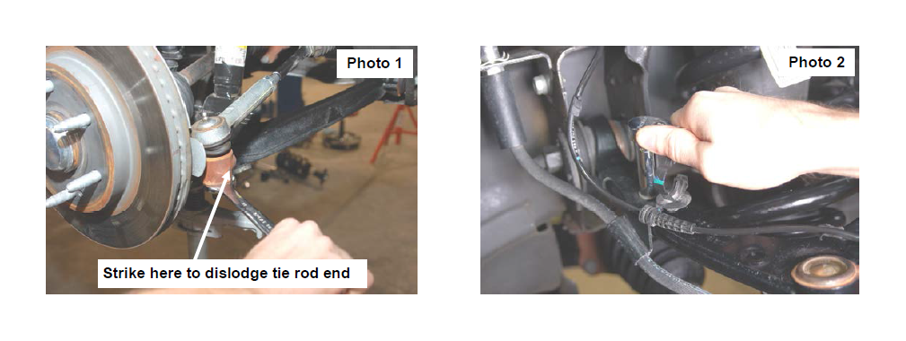
4. Using a 21mm wrench, remove the tie-rod nut as shown in Photo 1. Strike the side of the mount to dislodge the tie rod end. Remove from the knuckle.
5. Remove the sensor wire from the plastic clip. Remove the bracket from the control arm using a 10mm wrench. See Photo 2.
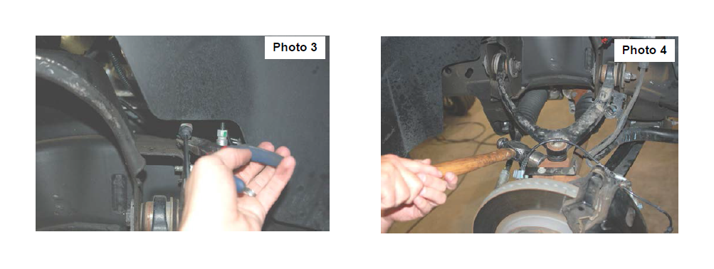
6. Remove and unplug the ABS sensor wire from the frame as shown in Photo 3.
7. Remove the upper ball joint nut using a 18mm wrench. See Photo 4. Strike the knuckle as shown to dislodge the ball joint. Separate the upper control arm from the knuckle.
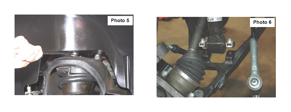
8. Using a 18mm wrench, remove the upper strut nuts as shown in Photo 5. Retain factory hardware for reuse.
9. Using a 15mm wrench, remove the 2 bolts securing the lower strut mount to the lower control arm and remove the strut from the vehicle. Remove and discard the factory lower retainer clips. New hardware will be used. See Photo 6.
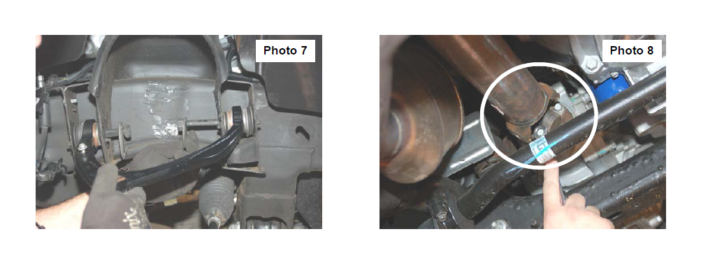
10. Mark location of alignment cams on upper control arms to allow installation of new arm to same position. Using a 21mm wrench and 21mm socket, remove the upper control arms from the vehicle. See Photo 7. Retain the hardware
11. Using a 11mm wrench, remove the drive shaft bolts. See Photo 8. Retain hardware for reuse.
12. Using a 18mm socket and wrench remove the four bolts holding in the factory cross member. Retain factory hardware. 13. Place a floor jack under the differential assembly to provide support for following steps.
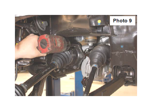
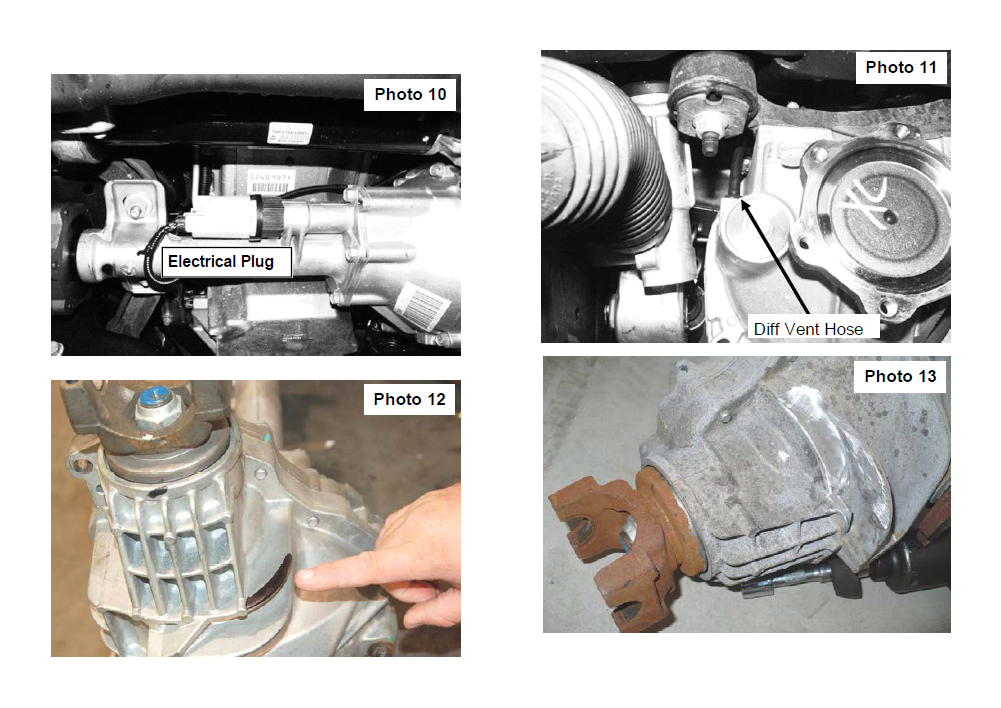
14. Using a 15mm scoket, remove the 6 axle shaft bolts and secure axle shafts out of the way. See Photo 9 Repeat on opposite side. Retain the factory hardware for reuse. Unplug the electrical connector on differential as shown in Photo 10 and unplug the diff vent hose. Photo 11
15. Using a 18mm socket remove the 4 differential bolts (2 each side) securing the differential to the frame. See Photo 9.
16. Slowly lower differential assembly to the ground.
17. Using a hand grinder. Grind away marked portion of the cooling fin as shown in Photo 12 and Photo 13. Grind until flush with casing.
18. Using 15mm and 18mm wrench remove the bolts holding the factory differential brackets on the driver and passenger sides.
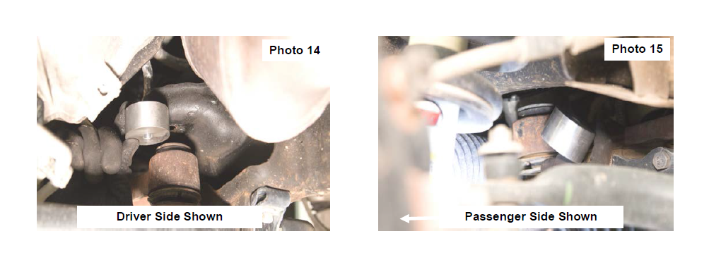
19. Place the 4 supplied aluminum differential spacers between the frame mounts and the factory differential brackets. See Photos 14 & 15.
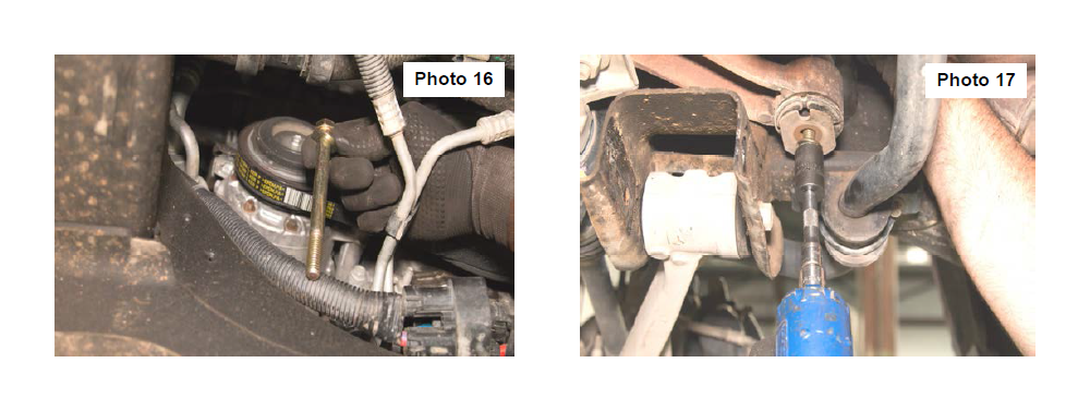
20. Using the supplied 7/16” x 5” bolts, nuts and washers from 275BAG4, attach the diff. mounts and drop brackets to the frame and tighten using a 5/8” wrench See Photos 16 & 17.
21. Reinstall the differential to the diff brackets with the factory bolts on the drive side and factory nuts on the passenger side. Tighten using a 18mm socket.
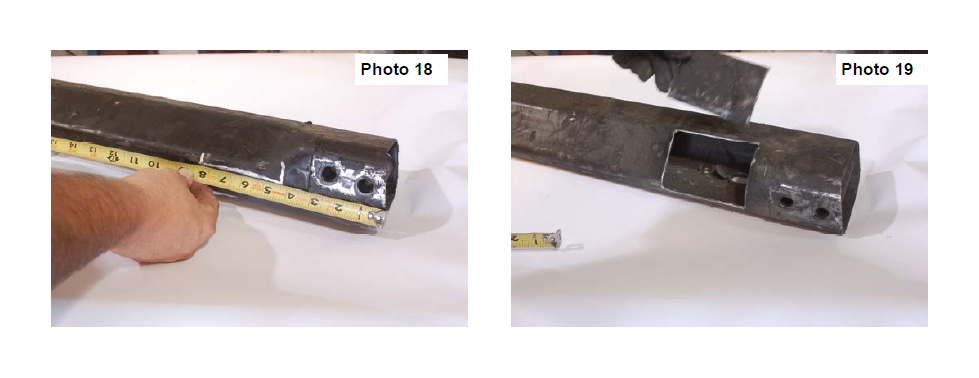
22. On the driver side of the factory cross member measure from the end of the tube and make marks at 4.5” and 8” on the front side as shown in Photo 18. Measure 1/4” for the bottom, and 2” from the back side and mark.
23. Using a die grinder and cut across the marks as shown in Photo 19. Hold the cross member into place and check clearance between the cross member and front diff.
24. Reconnect the connector plug on the differential & pull the vent hose down slightly and reinstall on the differential. The differential vent hose may be tapped to the electrical loom. If so separate and slightly pull for slack.
25. Reinstall the axle shafts to the differential with the factory hardware using a 15mm socket as removed in Step 15.
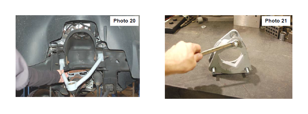
26. Install the new control arm as shown in Photo 20 in the factory mount making sure the 1/4” stud for mounting the brake line bracket is toward the rear with the factory hardware. Tighten using mark made as a reference in Step 10 and using a 21mm wrench & socket. Passenger side shown.
27. Locate the supplied strut spacer and install the supplied 10mm stud extensions. Using a 17mm socket snug the stud in the new spacer as shown in Photo 21.
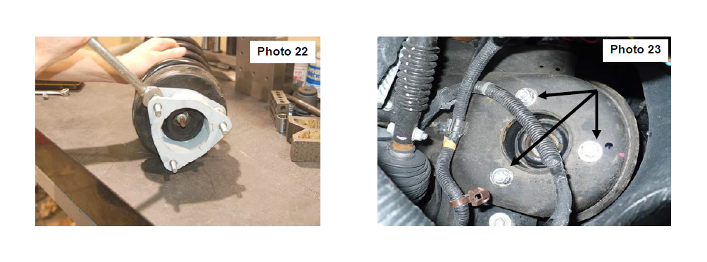
28. Install the strut spacer on the factory strut with factory hardware and using a 18mm wrench. See Photo 22.
29. Install the strut assembly in the factory mount with the supplied 10mm nuts/washers &l ock-washers on the upper mount. Tighten using a 17mm wrench. Note: Flat washer must be installed on studs. See Photo 23.
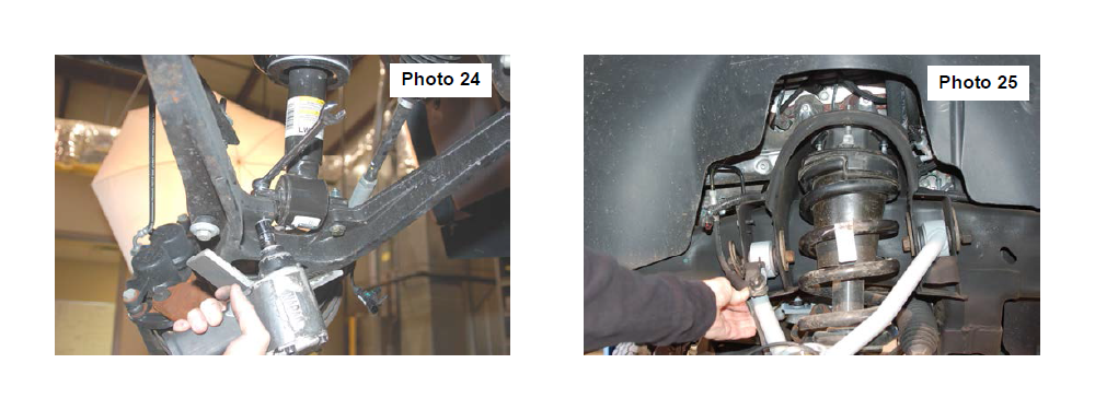
30. Install the strut in the lower control arm using the supplied 3/8” 2 1/4” bolts /washers & nuts using a 9/16” wrench. See Photo 24. It may be necessary to jack up the lower control arm with a floor jack to align lower strut holes.
31. Reinstall the sway bar on the lower control arm using a15mm wrench.
32. Reinstall the knuckle to the upper control arm with the supplied castle nuts/cotter pins. Tighten using 3/4” wrench to 50 ft/lbs. DO NOT OVER-TORQUE THE CASTLE NUT. Reinstall the tie rod end into the knuckle with factory hardware and using a 21mm wench.
33. Reinstall the driveshaft with the factory hardware using a 11mm wrench.
34. Install the brake line bracket on the new control arm with the supplied 1/4” lock nut / washer and using a 7/16” wrench. See Photo 25. Driver side shown.
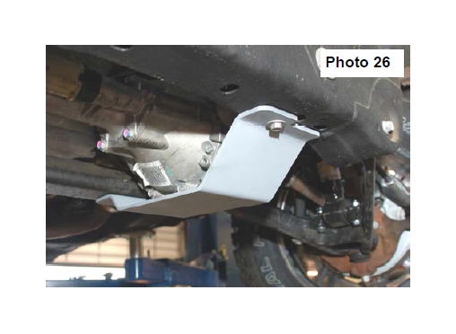
35. Locate and install the new lower skid plate below the differential in the factory location with the factory hardware and using a 15mm wrench. See Photo 26.
REAR INSTALLATION
1. Chock the front wheels.
2. Place a floor jack under the differential and jack up the rear of the vehicle.
3. Place jack stands under the frame rails and lower onto the jack stands.
4. Remove the tires/wheels.
5. Remove the factory shock absorbers using a 21mm wrench & socket. Retain the factory hardware for reuse.
6. Remove the factory u-bolts using a 21mm socket, then remove the factory blocks. Lower the axle using the floor jack to allow for the new 3” block to be installed.
7. Install the block on the factory spring pad with the flat part of the block on the spring and the thinner end towards the front. Jack up the axle to meet the springs, making sure to align the center pin. See Photo 1
8. With the floor jack applying slight pressure to the rear axle to keep the pin aligned, install the new supplied u-bolts and tighten in a crossing pattern, using a 7/8” socket.
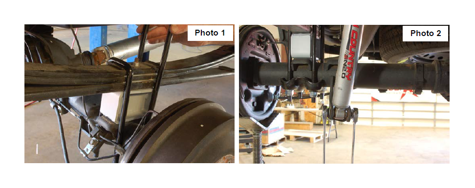
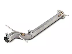
9. Locate the new shock absorbers part # 658726, and install the shock absorbers in the factory mounting locations using the factory hardware. Tighten using a 21mm wrench & socket. See Photo 2
10. Install the tires/wheels.
11. Jack up the vehicle to remove the jack stands. Remove the jack stands and lower the vehicle to the ground.
Box Kit
1-Driver Side Control Arm
1-Pass Side Control Arm
1-Driver Side Diff Bracket
4-Diff. drop spacers
2-Strut Spacers
4-9/16” x 10 1/2” U-bolts
2-3” spacer blocks
2-Rear Shock Absorbers
KIT CONTENT
1277Bag6:
4-3/8” x 2 1/4 bolts
8-3/8” washers
2-3/8” lock nuts
2-3/8 self tapping bolts
10mmstudbag:
6-10mm Studs
6-10mm Lock Washers
6-10mm Flat Washers
6-10mm Nuts
275Bag4:
4-7/16” Nuts
4-7/16” Lock Washers
4-7/16” x 5” Bolts
2-1/4” Lock Nuts
8-7/16” Hardened Washers
POST INSTALLATION INSTRUCITONS
1. Lightly grease the ball joints. Do not over grease the ball joint as this could cause ball joint boot failure.
2. Have a qualified alignment center align the vehicle immediately.
3. Have headlights adjusted to proper settings.
4. Wheels must be retighten at 50 miles.
5. All kit components must be retightened at 500 miles and then every three thousand miles after installation. Periodically check hardware for tightness.
6. Install “Warning to Driver” decal on sun visor.
7. On some vehicles the front lower skirting will need to be trimmed if using certain wheel /tire combinations and with heavy offset wheels. Trim only as needed.
CAB INSTALLATION INSTRUCTIONS
1. Raise hood disconnect positive and negative battery cable from the battery using 10mm wrench. This is done to prevent accidental airbag deployment. Check owners manual and remove airbag fuses to prevent accidental air bag deployment.
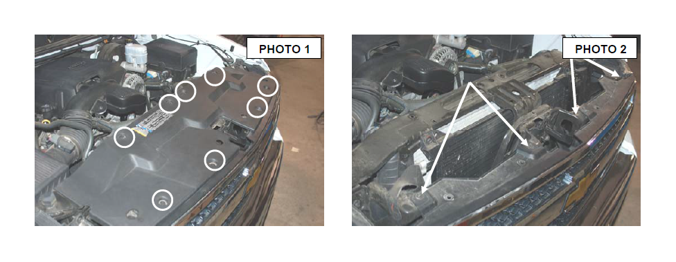
2. Remove the eight plastic clips from the radiator bezel using a screwdriver and remove bezel. Retain hardware for reuse. See Photo 1.
3. Remove 4 bolts from grill using a 10mm socket then pull on lower part of grill to release clips. Retain hardware for reuse. See Photo 2.
4. Remove four of the clips from the rubber shroud that is attach to the bumper. There are 9 clips total but only 4 need to be removed to remove bumper. Retain hardware for reuse.
5. Unplug fog lights on bumper if equipped.
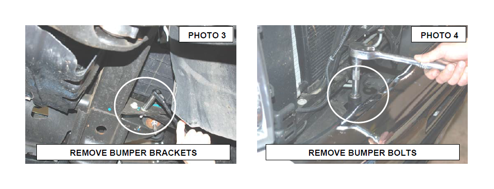
6. Remove the bumper support brackets located near front body mount that attach bumper to frame using a 15mm socket. See Photo 3. Retain hardware for reuse.
7. Remove the two upper bumper bolts using 21mm socket and remove bumper from truck. See Photo 4.
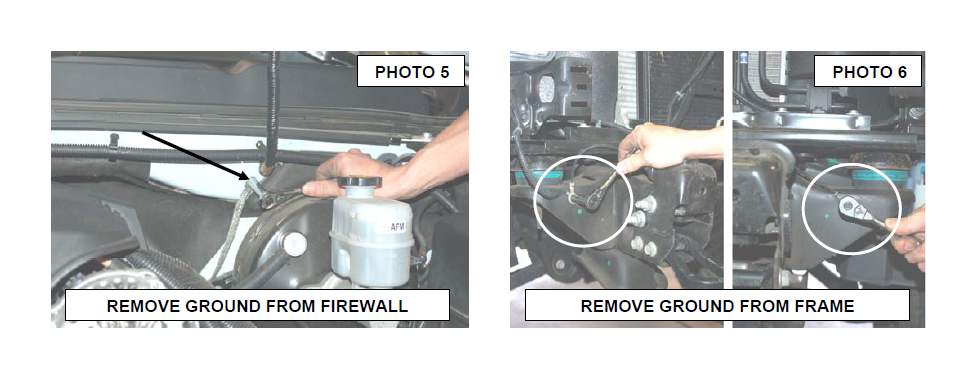
8. Remove ground wire from firewall using 10mm socket. Retain hardware for reuse. See Photo 5.
9. Remove both ground wires from frame located on front body mount using 10mm socket / wrench. Retain hardware for reuse. See Photo 6.
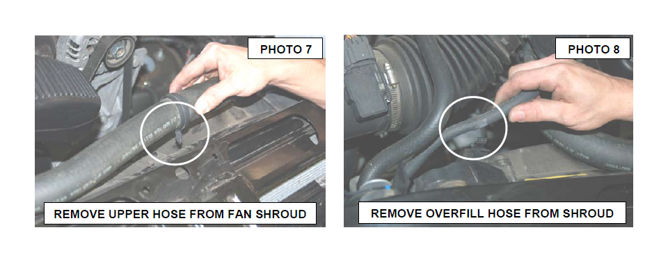
10. Remove upper radiator hose and overflow hose from fan shroud as shown in Photo 7 & 8.
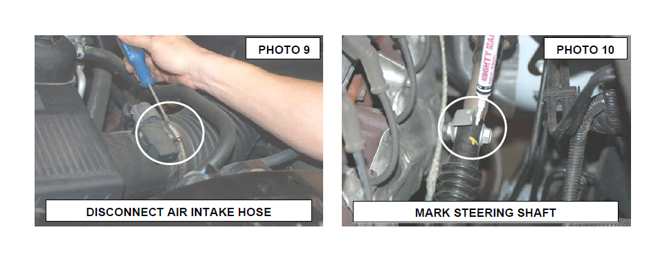
11. Disconnect air intake hose from air box using a Phillips screwdriver and needle nose pliers. See Photo 9.
12. Lock steering wheel and mark the location of the upper and lower parts of steering shaft. Remove the shaft bolt using a 15mm socket. See Photo 10. Do not turn or allow steering to turn while shaft is apart.
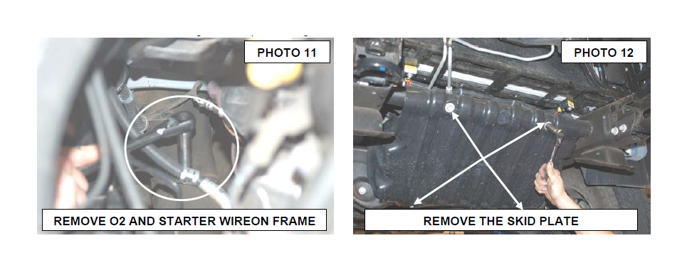
13. Remove starter wire and O2 sensor wire from frame on passenger side as shown in Photo 11 using a 13mm wrench and screwdriver or pliers
14. Remove the four bolt securing the skid plate using a 15mm socket. See Photo 12.
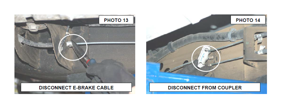
15. Disconnect the emergency brake cable at the connection on the frame below the drivers door by removing the front part of cable from frame just under the front part of driver door. See Photo 13 & 14.
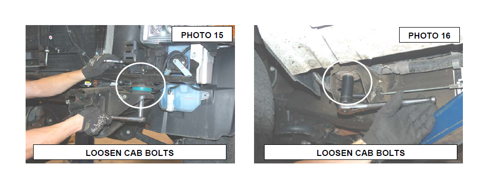
16. Loosen all cab bolts on driver and passenger side using a 15mm & 18mm for both front body mounts as shown in Photo 15 and 21mm for the other 6 cab mounting points as shown in Photo 16. Remove body mount hardware one side at a time.
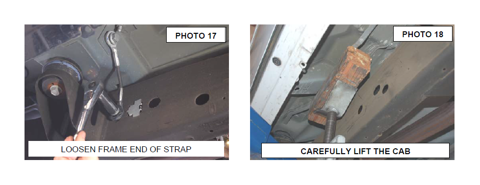
17. Photo 17 will is removing the cab support strap with a 18mm socket, this is only on a standard cab truck. If you have a extended or crew cab truck please skip this step.
18. Using a jack stand or hydraulic jack with wood blocks slowly lift body from truck. See Photo 18.
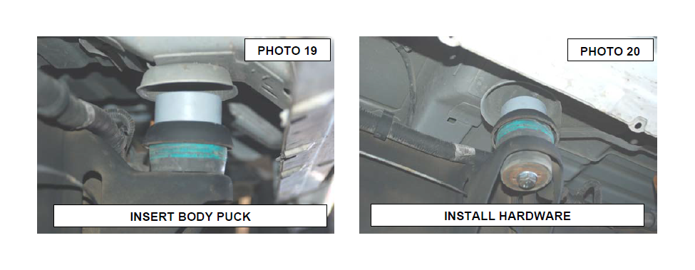
19. Lift only enough to place body puck on top of body mount. See Photo 19. Note: Passenger side front body mount bolt can be removed by lifting the body bushing out of frame so the bolt will pass by the A/C lines.
20. Apply thread lock to the three supplied 14x 2.0 x 140mm bolts and install for the 3 body mount on pass side. See Photo 20.
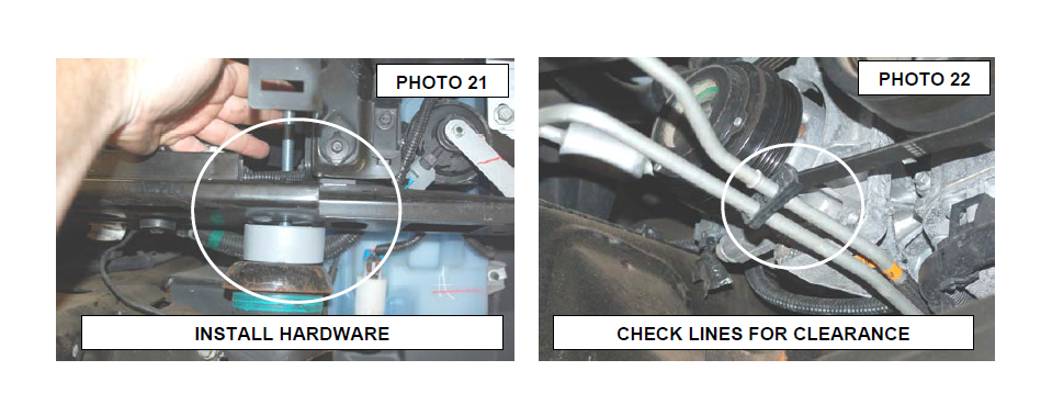
21. Apply thread lock to the two supplied 12mmx 1.75 x 140mm bolt and install for the front body mounts. Do not tighten at this time. Note: Install front body mount bolt in same way as it was taken out to clear A/C lines. See Photo 21.
22. Repeat for Drivers side.
23. Tighten all 14mm bolts to 95ft-lbs using 22mm socket and all 12mm to 65ft-lbs using 18mm socket.
24. Check trans lines make sure the are not rubbing A/C compressor bracket or belt tensioner on some models. Bend lines away if necessary. See Photo 22 & 23
25. Reinstall front skid plate with stock hardware and tighten using 15mm socket / wrench to 20 ft-lbs torque.
26. Reconnect engine ground to firewall using supplied ground extension bracket and supplied 1/4” x 3/4” bolt. Tighten with a 11mm socket. See Photo 24.
27. Reconnect both front body mount ground wires as previously removed in stock location using a 10mm socket.
28. Reconnect O2 sensor and starter wire to frame on passenger side using a 13mm socket.
29. Reconnect upper and lower parts of steering shaft. Tighten using a 15mm socket to 40 ft-lbs.
30. Reinstall intake hose to airbox and reconnect radiator hose to top of radiator.

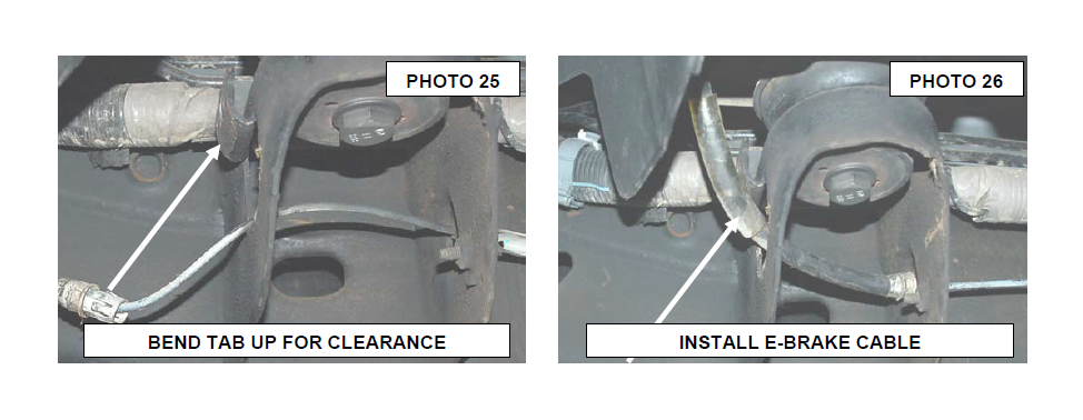
31. Find the tab on driver side body mount where the emergency brake cable runs beside it and bend it up flat with frame to gain slack for cable. See Photo 25.
32. Run cable back in its original location and reconnect to rear part of cable. See Photo 26.
33. Step 33 and 34 are only used on standard cab trucks, attach the factory strap to the bracket with stock bolt and rubber washer and the supplied 12mm flange locknut. Tighten with a 18mm socket and 19mm wrench.
34. Using the supplied 12mm x 35mm long bolt and washer attach the bracket to the factory frame hole. Tighten with a 18mm socket. See Photo 27
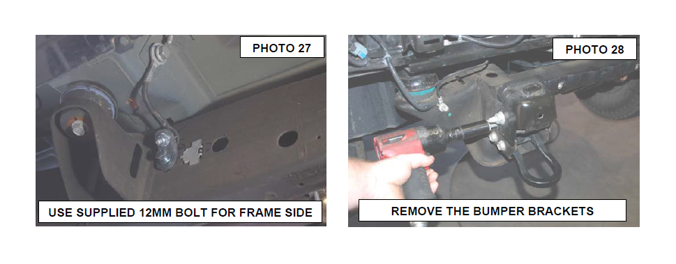
35. Remove the two bolts from driver and pass front bumper brackets using 21mm socket. See Photo 28. Retain stock hardware.
36. Mark the front tow hooks as driver and passenger top and remove hardware using 18mm socket. See Photo 29. Retain stock hardware.
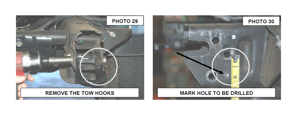
37. Measure 1-7/16” down from second bumper mounting hole and mark. See Photo 30. Drill using a 1/2 drill bit. Spray some paint on new hole. Do the same for other side.
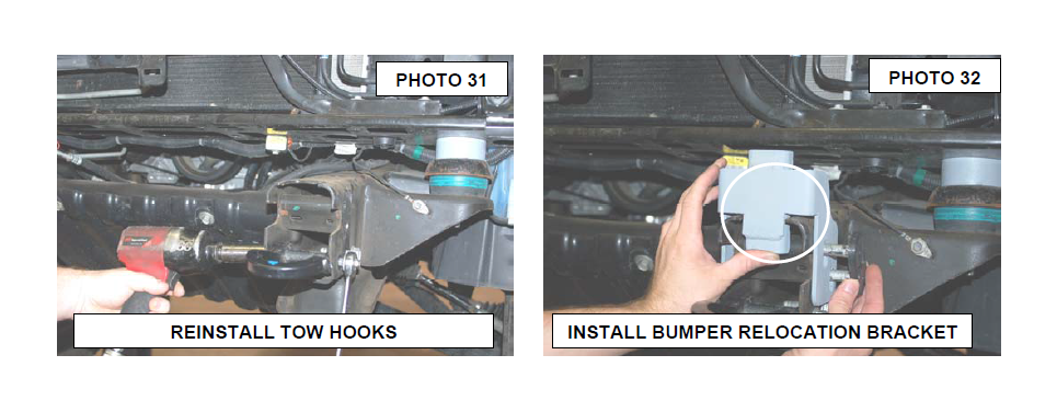
38. Install tow hooks so that they are upside down and install stock bolts. Tighten to 65ft-lbs using a 18mm wrench / socket. See Photo 31.
39. Install new front bumper brackets using stock hardware. Adjust bracket up as high as it will go and tighten using 21mm socket / wrench. See Photo 32.
40. Install new lower bumper bracket on driver and passenger with supplied 3/8” x 1” bolts, washers and lock nuts. See Photo 33. Do not tighten at this time.
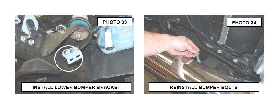
41. Install front bumper using stock hardware. Adjust bumper so that it is straight on truck. Tighten hardware with 21mm socket / wrench. See Photo 34.
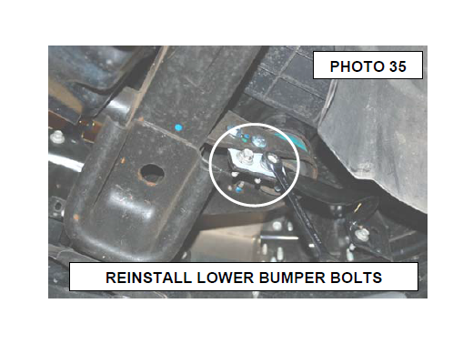
42. Install lower bumper brackets using stock bolts. Tighten using a 15mm socket / wrench for stock bolts and 14mm for new bolts. See Photo 35.
43. Reinstall rubber shroud with stock clips and then install grill using 10mm for stock bolts.
44. Reinstall radiator bezel with the stock 8 clips.
BED INSTALLATION INSTRUCTIONS
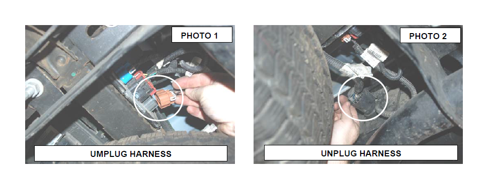
1. Unplug the license plate light connector and if equipped the trailer wiring connector. See Photo 1 & 2.
2. Remove the 3 bolts from the driver and passenger side frame as shown in Photo 3 (Driver Side Shown) that mount the bumper to frame. These six bolts ( three per side) are removed using a 18mm and 15mm socket / wrench. Retain the stock hardware.
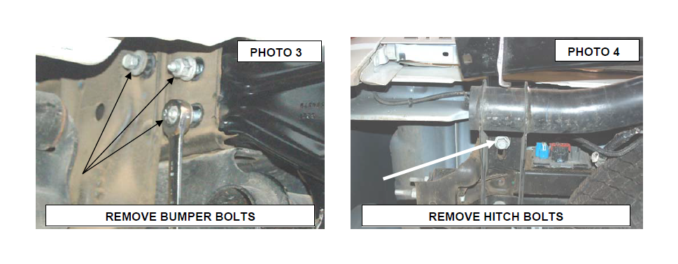
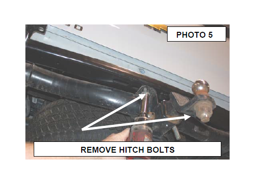
3. Using a 21mm socket remove the 4 bolts located in the receiver hitch. See Photo 4 & 5.
4. Remove bumper and set aside.
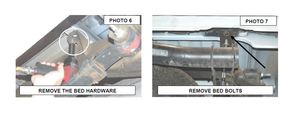
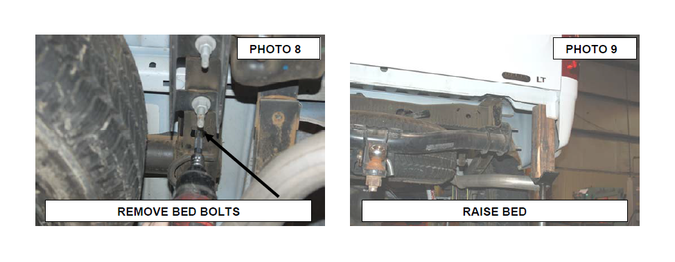
5. Loosen the six bed bolts using 18mm socket but only remove one side at a time. See Photo 6, 7 & 8.
6. With jack stand or hydraulic jack and wood block raise passenger side slowly. See Photo 9. Raise bed up enough to install body pucks.
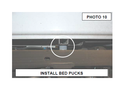
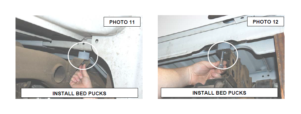
7. Install 4 pucks per side and add lock tight on the supplied 12mmx 65mm bolts / washers and install. Torque to 65 ft/ lbs. NOTE:Make sure fuel filler tube is un-obstructed during lift of driver side. See Photo 10, 11 & 12.
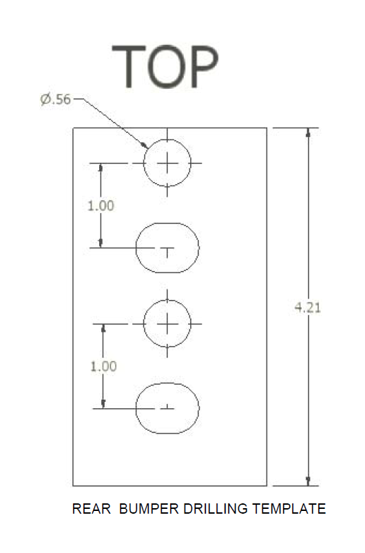
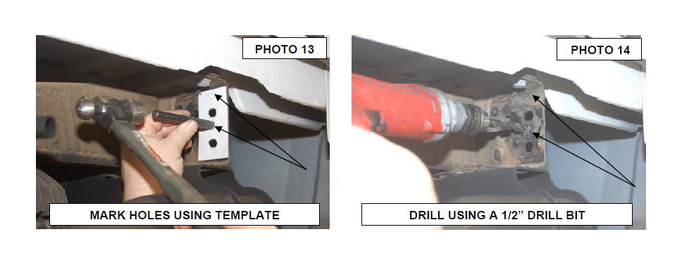
8. With bumper still removed, use the supplied template to mark and drill the new holes in the frame. See Photo 13.
9. Drill the holes using a 1/2” drill bit. See Photo 14.
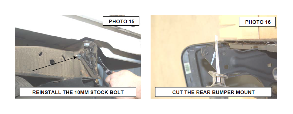
10. Reinstall the stock 10mm bolt using the supplied 10mm lock nut back in the frame. Tighten using a 15mm and 17mm wrench. See Photo 15.
11. Mark and cut the outer mount off of the bumper as shown. Clean and paint the area to prevent rust. See Photo 16.
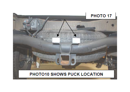
12. Photo 17 shows the placement of the hitch pucks with the 9/16” ID holes with the bumper not yet installed. This is just to give you an ideas as to where the pucks will be installed.
13. Reinstall the factory bolts in the newly drilled holes in the frame. Do not tighten at this time. .
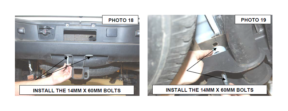
14. Reinstall the bumper on the mounts and install the supplied 14mm x 60mm bolts in the hitch as shown in Photo 18. Do not tighten at this time.
15. Install the 1” tall body pucks as shown above the frame, under the rear bumper mounts to move the bumper up. Secure with the supplied 14mm x 60mm bolts. Do not tighten at this time. See Photo 19.
16. Align bumper where the bumper is spaced equally on both sides and tighten the 14mm bolts using a 22mm socket / wrench and the factory bolts using a 18mm socket / wrench.
17. Reconnect battery cable and tighten.
POST INSTALLATION INSTRUCTIONS
1. Check all fasteners for proper torque. Check to ensure for adequate clearance between all rotating, mobile, fixed, and heated members. Test and inspect brake system.
2. On some vehicles the front lower skirting will need to be trimmed if using certain wheel /tire combinations and with heavy offset wheels. Trim only as needed.
3. Activate four wheel drive system and check front hubs for engagement.
4. Perform head light check and adjustment to proper settings.
5. All kit components must be retightened at 500 miles and then every three thousand miles after installation. Periodically check all hardware for tightness.
6. Install “Warning to Driver” decal on sun visor.