 FREE 1 to 3-Day Delivery on Orders $149+ Details
How to Install PIAA RF Series 6 in. LED Light Bar - Fog Beam on your Silverado
Before starting the work procedures...
※ The following work procedures shown below are for the "RF6" model but the same procedures can also be used for units "RF10" and "RF18".
By using the Connection bracket (Item ⑨ ) 2 main lamp units (Item ① ) can be connected. When installing and using the main lamp unit, follow the ■ Lamp connection procedures indicated below. If not installing the main lamp unit using this procedure continue on to page 5, [1] Installation preparations and follow the instructions indicated there. In addition, if not connecting the lamps, the Connection brackets (Item ⑨ ) and the Hexagon socket head bolt (M4/Item ⑩ ) will not be used. Therefore, please store them properly for safekeeping.
■ Lamp connection procedures
Install the Connection bracket (Item ⑨ ) to the nut on the lamp main unit as shown in the figure. Use the Hexagon socket head bolt (M4/Item ⑩ ) to secure it firmly in place.
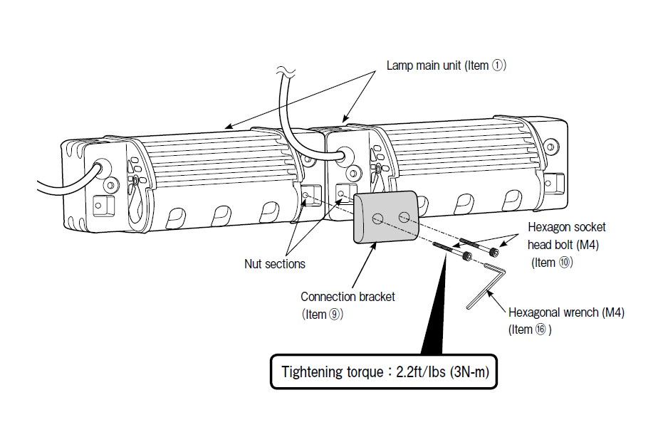
● Use the recommended torque and apply equal force when tightening the Hexagon socket head bolt (M4/Item ⑩ ).
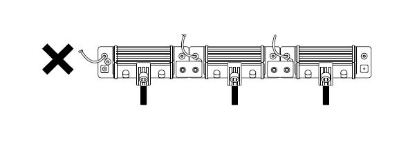
● Do not install more than 3 lamp main units.
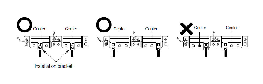
● When connecting lamp units“ RF6” and“ RF10”, we recommend that 2 Installation brackets (Item ②) be used on each lamp unit.
If there is a problem with the installation position and only one Installation bracket can be installed on each lamp, install it on the outer hole from center.
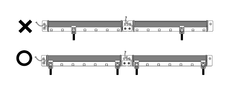
● When installing and using the“ RF18” unit, make sure to install 2 Installation brackets (Item ②) at 2 positions on each lamp.
?1?Installation preparations
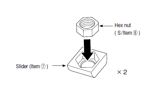
(1)Combine the Slider (Item ⑦ ) and the Hex nut ( S/Item ⑧ ) as shown in the figure below.
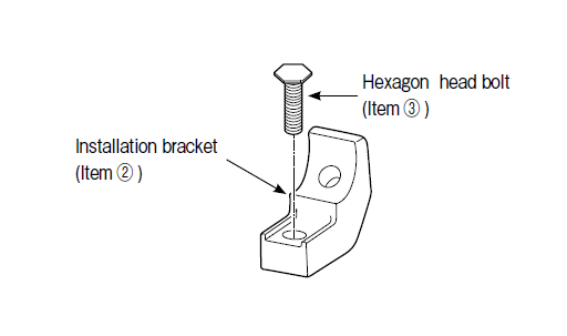
(2)Combine the Installation bracket (Item ② ) and the Hexagon head bolt (Item ③ ) as shown in the figure below.
● If installing the lamp main units“ RF10 and “RF18” to the vehicles without combining them, make sure to install 2 Installation brackets on 2 positions on the lamp main unit. With unit“ RF6”, one Installation bracket can be used in the center but we recommend installing them on 2 positions.
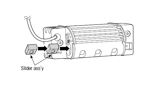
(3)Take 2 sets made up of the Hex nut and Slider assembly that was combined in (1) put them into the lamp main unit positions as indicated in the figure. Be careful not to drop the Hex bolt out of the Slider.
(4)Take 2 sets made up of the Hex nut and bracket assembly that was combined in (2) and using the Hexagon socket head bolt (M10/Item ⑥ ), screw it firmly in place.
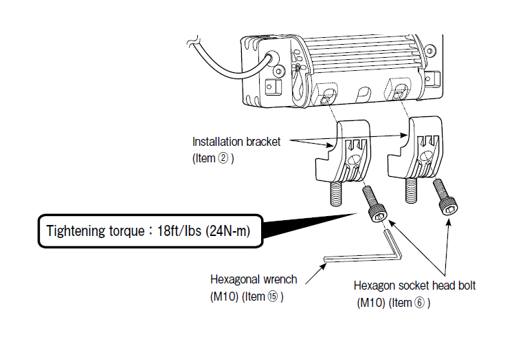
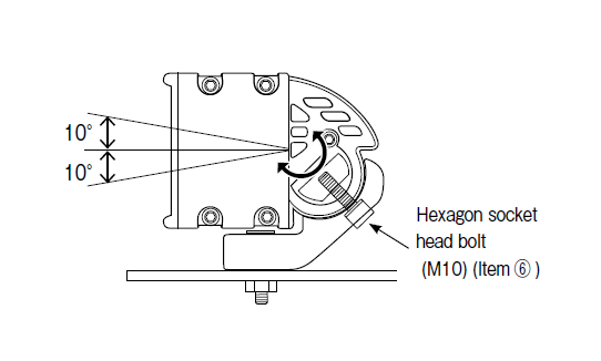
● After the lamps are installed on the vehicle, the Hexagon socket head bolts (M10/Item ⑥ ) can be loosed and the angle of the lamp can be adjusted.
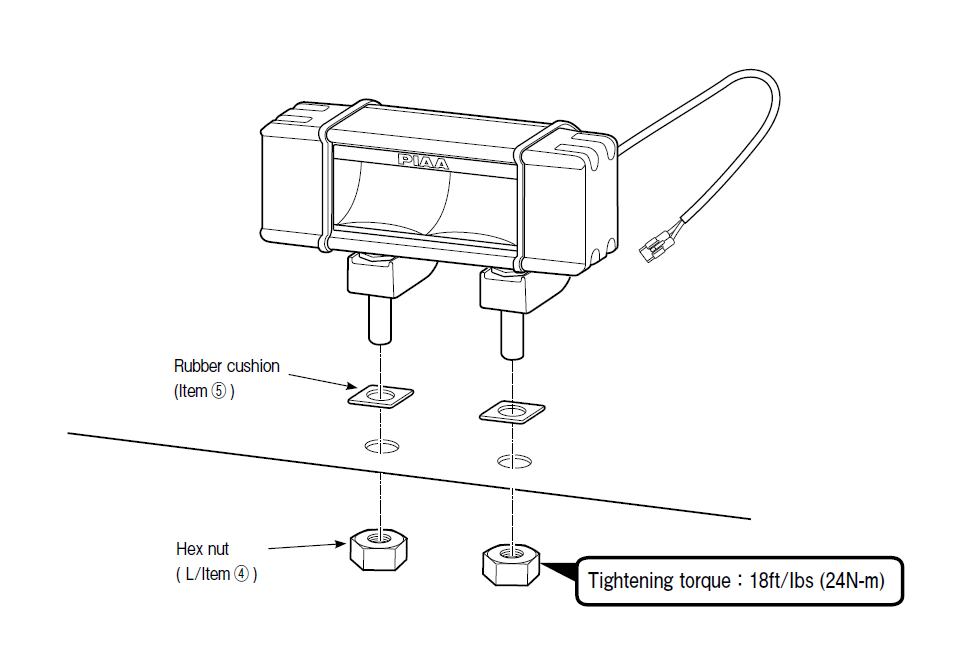
?2?Lamp installation
For lamp installation, a hole with a diameter of 10mm is required. Make necessary preparation such as installation of lamp bracket.
CAUTION
● When using a commercially supplied lamp bracket, before removing the bolt that is already installed on the car body, make sure that it is safe to do so.
● The lamp should be mounted in an area sufficient to support its size and weight.
Failure to do so may result in excess vibration leading to shorter bulb life and or physical damage to the lamp or your vehicle.
● Do not attempt to install the lamp directly to any plastic part of the car body.
If the lamp needs to be installed on the plastic reinforcement materials should be placed on both sides of the plastic part.
● When installing, make sure the lamp body, lens and rim are not touching the bumper and other plastic parts. Such plastic parts might deform.
● The lamp installation surface should be flat.
● The lamp should be tightened to the degree that the lamp body cannot be moved by hand.
● The lamps are designed to be mounted upright. It is very important that you make sure that the“ PIAA” etched in the lens reads right side up.
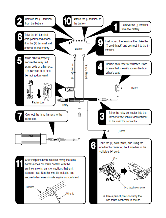
?3?Relay Harness Installation Sequence
The numbers shown in the figure below indicate the sequence the parts should be installed.
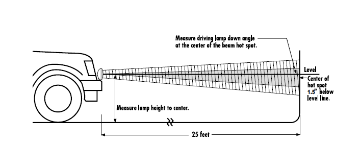
DRIVING / Spot Light Aiming
Typically, driving lights are mounted above the front bumper about 30 inches from the ground to provide extra high beam illumination. Driving lights can be mounted below the bumper, although they will not be as effective because the light will hit the ground sooner and reduce the range of the light.
Visual aim is made with the center of the beam hot spot 1.5 inches below the lamp center at 25feet with the lamp facing straight forward. (see below.)
CAUTION
● Do not use driving lights into oncoming traffic. Driving lights should never be the only forward light source. Driving lights should only be used with the headlamp high beams.
?4?Troubleshooting……Verify each section according to the following.
1. After installation, if the lamp does not activate
→ Check the wiring and make sure there are no faulty or irregular connections .
● If the switch illumination does not light up.
→ Verify the ( ) wire from the switch is properly connected. If it is not correctly connected it will not activate.
→ Verify the fuse located on the vehicle's wiring system. (the switch's ( ) wire should be connected to the fuse box). If it is burned out, connect it to another circuit.
→ If the switch itself is faulty, the same symptoms may exist. We recommend that the entire switch unit be replaced.
→ Check the fuse for the switch harness. If it is burned out, follow instructions indicated in [ 3 Fuse replacement Procedures].
● The switch illumination lights up but when operating does not work.
→ Check the connecting (-) cord to the body earth.
→ There may be cases where each terminal related to specific sections may be incorrectly connected.
Check for any lose wires and also for dirt or grime.
→ Check the switch operation If an abnormality is found, replace it accordingly.
2. If the LED suddenly fails to light up …
→ Check the fuse located on the vehicle's wiring system. If it is burned out, replace accordingly.
→ Check the fuse for the switch harness. If it is burned out, follow instructions indicated in [ 3 Fuse replacement Procedures].
→ There may be cases where each terminal related to specific sections may be incorrectly connected.
Check for any lose wires and also for dirt or grime.
→ Check the switch operation if an abnormality is found, replace it accordingly.
3. Fuse replacement procedures
→ A short circuit may have occurred. Check the wiring system. If any type of damage is found replace accordingly. (Non-replacement may pose a potential danger) (Short circuits are mainly caused when wires are caught in the assembly or when there is a gap in the sleeve connected to the lamp harness).


