 FREE 1 to 3-Day Delivery on Orders $149+ Details
How to Install Putco Crossrail Locker Side Bed Rails on your Dodge Ram
Tools Required
- ¼” Hex Wrench
- Dremel
- Drill (If Drilling)
- 5/16” Drill Bit (If Installing with Toolbox)
- Torque Wrench (If installing Nylon Castings)

Shop Parts in this Guide
Please read all instructions before installation and to check to see that all parts are included.
Locker Rail Installation
1. Remove locker kit from packaging. Verify all parts from above kit contents table are included.
2. Some stake pocket holes are covered with a plastic bed cap. Using a “Dremel” or similar tool, cut out the plastic covering the hole. Note: In some cases, the stake pocket holes are smaller than the molded outline in the plastic bed cap. To ensure there are not gaps around the locker casting, do not cut more of the plastic bed cap than is needed.
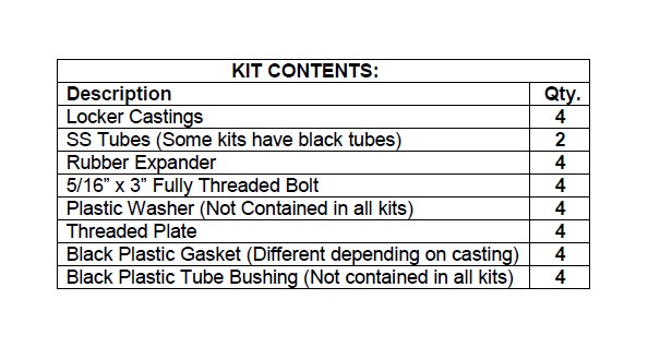
3. Place a tube bushing on each locker casting so that the tabs face towards the tube. Refer to Figure 1 below. (If you have black nylon castings, skip this step.)
Locker Rail Kit
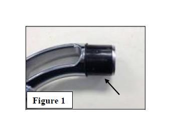
4. Assemble castings and mounting hardware for the front and rear stake pockets. If plastic washer is included, put plastic washer on the bolt. Insert the bolt through the top of the casting. Insert the gasket, expander, and threaded plate on the bottom and finger tighten and place the assemblies into the front stake pockets as shown in Figure 2.
5. Insert the casting into the tubes (If tube is tight on casting use a rubber mallet to install, be careful not to scratch the casting)
6. Install assembled rail on truck by sliding tube into front locker casting and inserting the rear casting assembly (Put together in step 4) into rear stake pocket.
7. Tighten front and rear locker casting bolts using ¼” hex drive. (If installing Nylon Locker Castings, torque bolts to 27 ft-lb)
Tool Box Locker Rail Installation without Diamond Donut
See Putco catalog or contact Putco for the “Diamond Donut” option to mount your rails directly to the side of your toolbox.
1. Place a casting, without the bolt, gasket, expander or back plate, into the open end of the tube.
2. Place assembled tube onto truck by inserting the cover plate and bracket of the assembled casting into the rear stake pocket.
3. Center the front casting, left to right, on your truck’s bed rail near the toolbox.
4. Mark the center of the hole in the casting on your truck’s bed rail.
5. Using your drill and 5/16” drill bit, center the drill bit on the mark you made from Step 4 above and drill straight through the bed rail of your truck.
6. Place the casting assembly back onto the bed of your truck, again by placing the cover plate and bracket into the rear stake pocket refer to step 5 of the normal Locker Rail Instructions.
7. At the front casting, place a 5/16” bolt through the casting, oval gasket and the hole you drilled in Step 5. Place the expander block on the bolt and turn on a threaded plate and tighten with ¼” hex drive.
8. Repeat the steps in this section for other side.
Clean Locker Rails
1. Clean the locker rails with a streak free cleaner.
2. Apply a protective coating of high quality automotive wax.


