FREE 1 to 3-Day Delivery on Orders $149+ Details
How to Install Fabtech 6 in. Performance Lift System w/ Dirt Logic 2.5 Coilovers & Shock
Installation Time
3 hours
Tools Required
- FLOOR JACK & JACK STANDS
- ASSORTED METRIC AND S.A.E SOCKETS, & WRENCHES
- LARGE C CLAMP OR C CLAMP VISE GRIPS
- DIE GRINDER WITH CUTOFF WHEEL OR SAWZALL
- TORQUE WRENCH

Shop Parts in this Guide
- Fabtech 6-Inch Performance Suspension Lift Kit with Dirt Logic 2.5 Coil-Overs and Shocks (07-13 2WD/4WD Silverado 1500 Extended Cab, Crew Cab)
- Fabtech 6-Inch Performance Suspension Lift Kit with Dirt Logic 4.0 Coil-Overs and Shocks (07-13 2WD/4WD Silverado 1500 Extended Cab, Crew Cab)
- Fabtech 6-Inch Basic Suspension Lift Kit with Shocks (07-13 2WD/4WD Silverado 1500)
FRONT SUSPENSION INSTRUCTIONS:
1. Disconnect the negative terminal on the battery. With the vehicle on level ground and the emergency brake set, block the rear tires. Jack up the front end of the truck and support the frame rails with jack stands. NEVER WORK UNDER AN UNSUPPORTED VEHICLE! Remove the front tires.
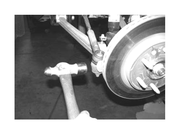
2. Disconnect the tie rod ends from the steering knuckle by striking the knuckle to dislodge the tie rod end. Use care not to damage the tie rod end when removing. SEE PHOTO BELOW.
3. Unplug the ABS brake connection from the frame and control arm. Remove the brake hose bracket from the steering knuckle. Remove the brake hose bracket from the coil bucket and save hardware. Remove the caliper from the rotor and secure the brake caliper to the frame out of the way. DO NOT ALLOW THE BRAKE CALIPER TO HANG FROM THE BRAKE LINE HOSE. SEE PHOTO BELOW.
4. Remove the wheel stud clips and discard. Remove rotor with hub bearing. (DO NOT REMOVE THE HUB FROM THE ROTOR). Retain parts and hardware for reinstallation.
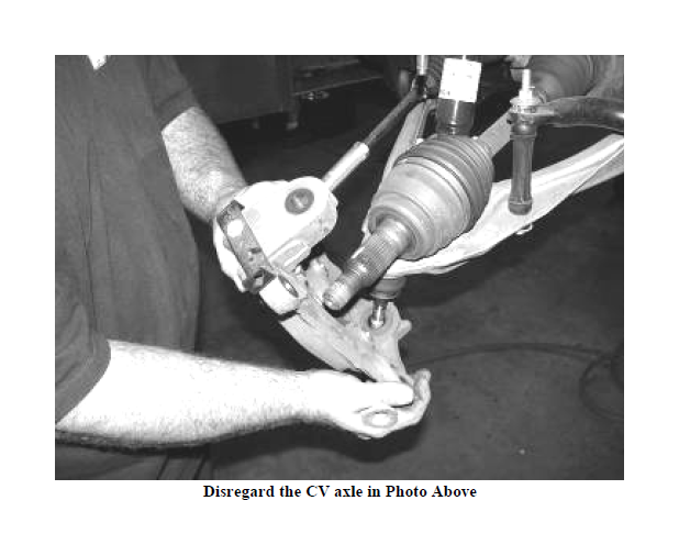
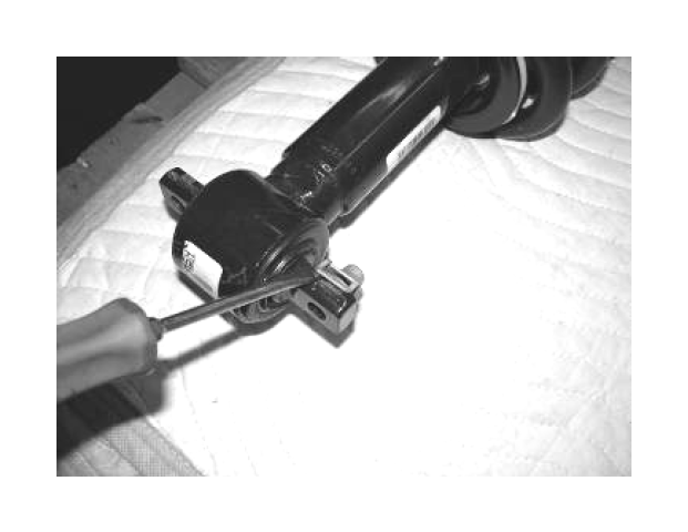
5. Remove the upper and lower ball joint nuts. Disconnect the upper and lower ball joints from the steering knuckle by striking the knuckle with a large hammer next to each ball joint on the knuckle to dislodge the ball joints. Use care not to hit the ball joints when removing. Save nuts and discard knuckle. SEE PHOTO BELOW.
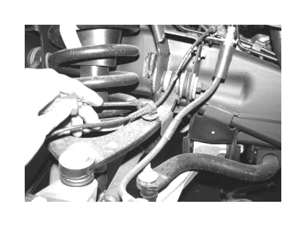
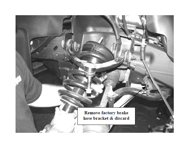
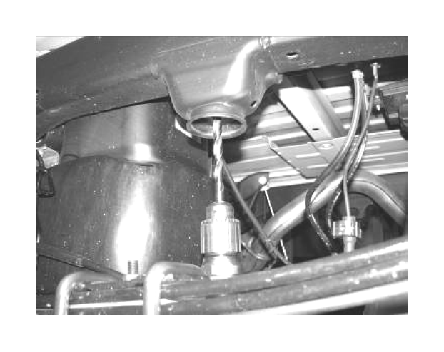
6. Remove the shock assembly and save with the hardware. Remove and discard the factory brake line bracket from the brake hose that attached the hose to the upper control arm. SEE PHOTO BELOW.
7. Disconnect the sway bar endlinks and save.
8. Remove the lower control arms from the frame and retain with the hardware for reinstallation. SEE PHOTO ON NEXT PAGE.
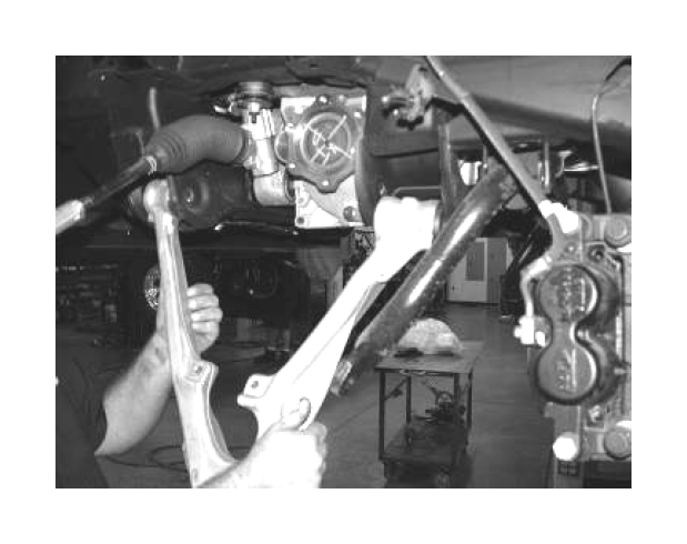
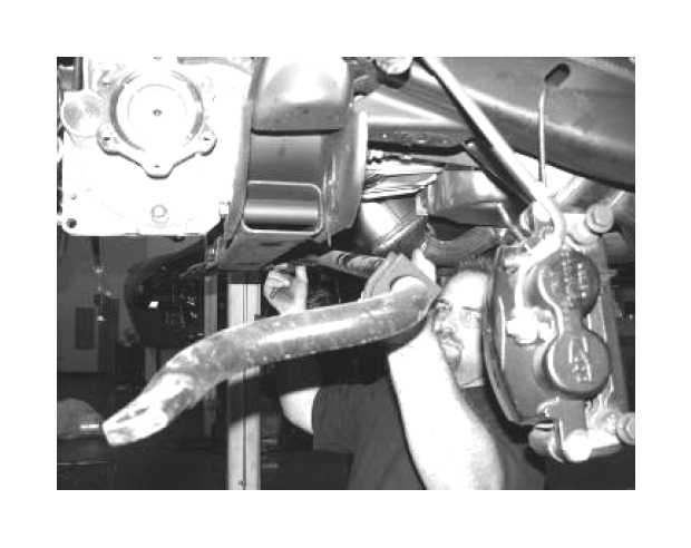
9. Locate, remove, and save the sway bar, discard hardware. SEE PHOTO BELOW.
10. Remove front factory splash shield and discard, if equipped.
11. Locate the factory front lower control arm pockets. Grind ¼” section from both Corners of the pockets as shown in the photo. SEE PHOTOS IN NEXT COLUMN.
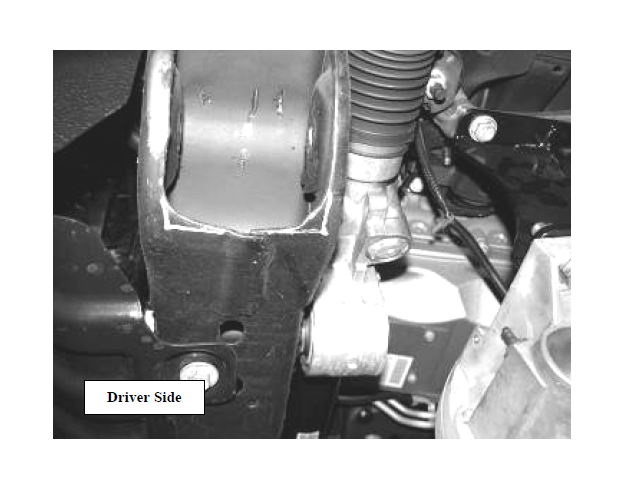
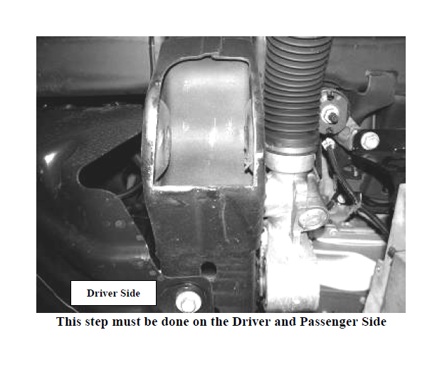
DUE TO VARIANCES IN EACH TRUCK, ADDITIONAL GRINDING MAY BE REQUIRED FOR PROPER FITMENT OF THE CROSSMEMBERS. USE THESE MEASUREMENTS AS A STARTING POINT AND CLEARANCE THE FRAME POCKETS AS NEEDED FOR PROPER FITMENT OF THE CROSSMEMBERS
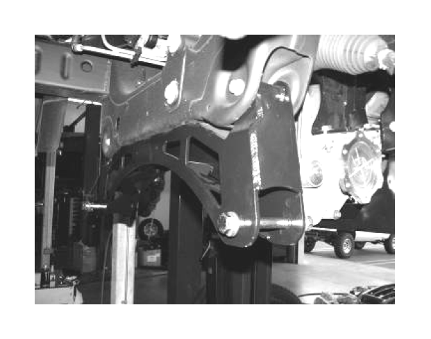
12. Locate and install FT20374 rear crossmember into the factory lower control arm pockets using the stock hardware and leave loose at this time.
13. Locate and install FT20373 front crossmember into the factory lower control arm pockets using the stock hardware. Leave loose. SEE PHOTO ON NEXT PAGE.
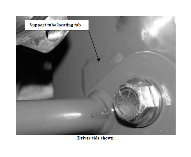
14. Locate FT20284 Crossmember Support Tubes. Install the lower control arms into the new crossmembers using the 5/8” x 5” hardware in the front pocket. Position the control arms into the crossmember and insert only the front 5/8” bolt just so that it is through the arm. Position the Support tube between the crossmembers and rotate them up to the locating tabs on the crossmember. Install 5/8” x 5 ¾” hardware in the rear pocket and the front bolt with hardware. Leave loose. SEE PHOTO BELOW.
15. Torque the crossmember frame pocket bolts to 125lbs, the lower control arm bolts to 110 ft lbs.
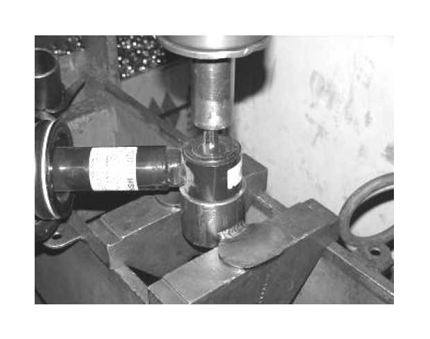
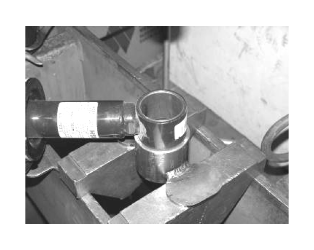
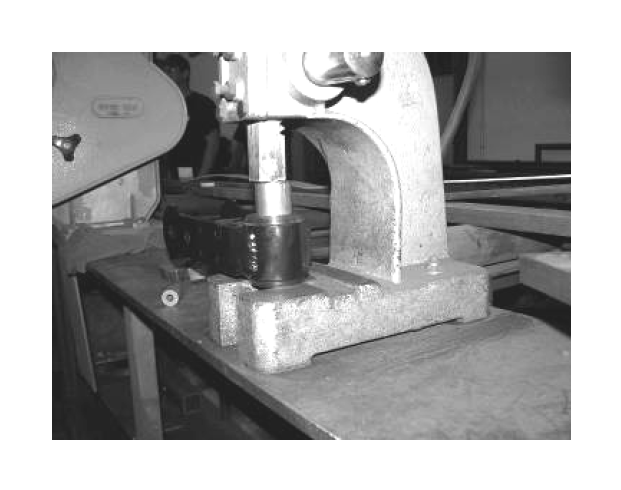
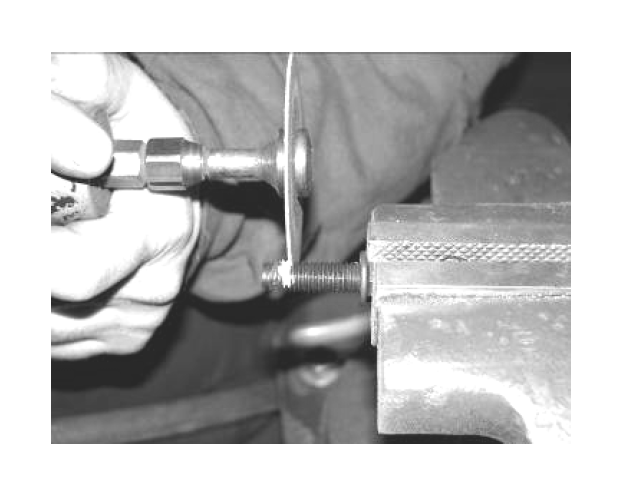
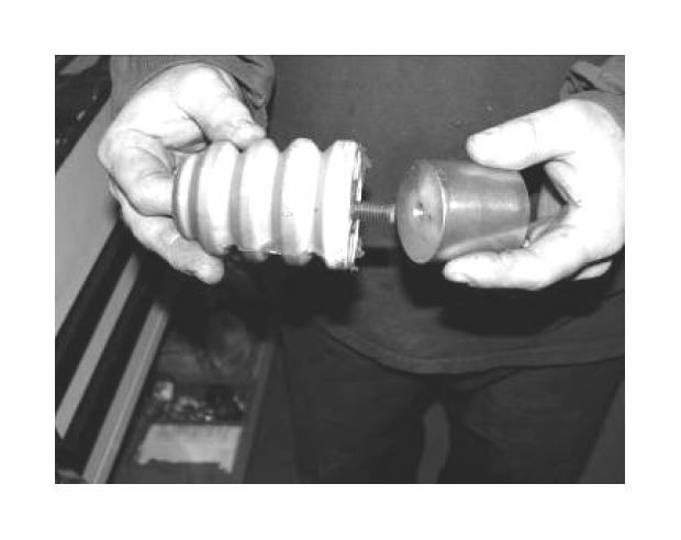
16. Locate the factory coilovers. Remove the nut clips from the cross-shaft and discard. Using a press, press out the cross-shaft and the bushing from the bottom of the coilover and discard. SEE PHOTOS IN NEXT COLUMN.
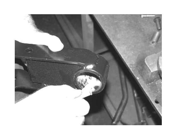
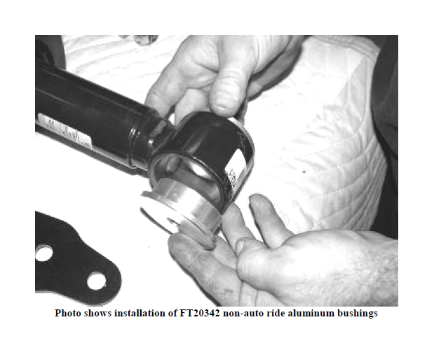
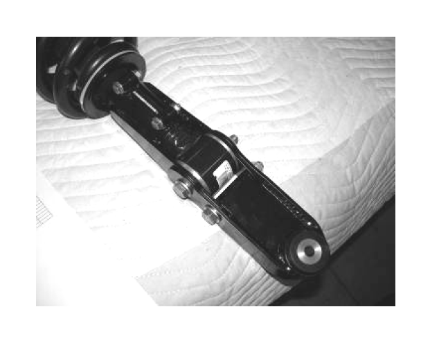
17. Locate Box 3 FTS21042BK which has FT20339 Shock Mount to Arm, FT20323 Shock Extensions, FT20568 Shock Brackets, FT20342 (non auto-ride) or FT20351 (auto-ride) Aluminum Bushings , Hardware Kit FT20295, FT1036 Bushings, and FT148 Sleeves. Using a press, press the bushings and sleeves (with the provided lube) into the shock extension. Insert the Aluminum Bushings into the bottom of the factory shock. SEE PHOTOS ON NEXT PAGE.
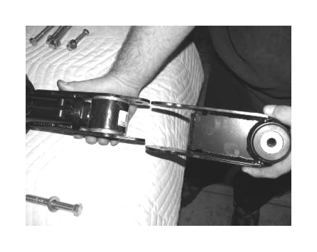
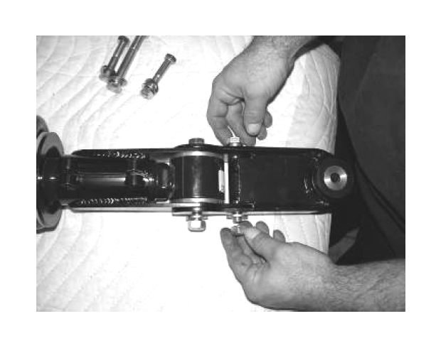
18. Place the Shock Brackets around the bottom of the shock and align with the aluminum sleeves. Position the shock extension over the brackets and also align with the aluminum sleeves. Locate the supplied ½” x 4” bolts and hardware and install through the aluminum bushing and the shock mount. Leave loose. Locate the 5/16” x 1 ½” bolts and hardware and install into the shock brackets. Tighten the 5/16” hardware so the brackets are evenly spaced on the shock. Torque to 20 ft lbs. Torque the ½” hardware to 75 ft lbs. SEE PHOTOS BELOW AND ON NEXT PAGE.

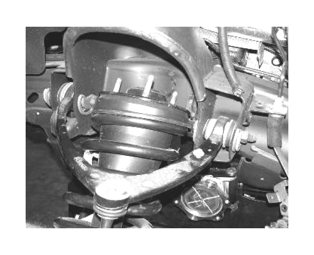
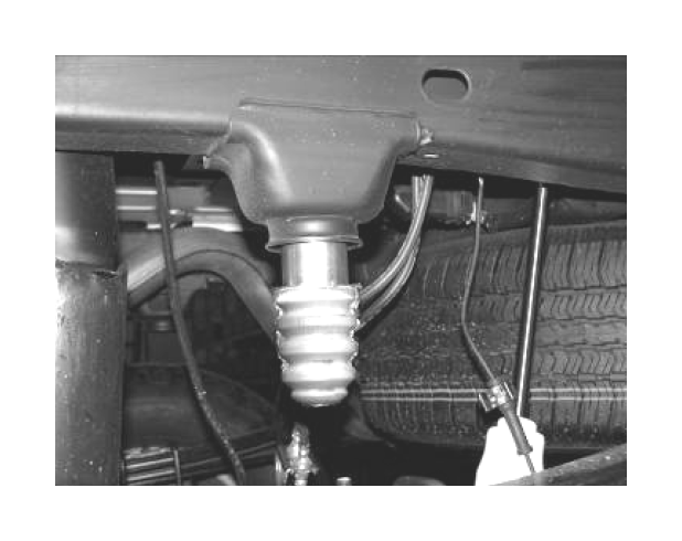
19. Locate the factory upper shock hardware. Install the shock into the factory shock bucket and leave loose. SEE PHOTO BELOW.
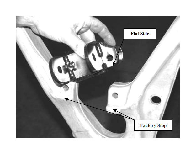
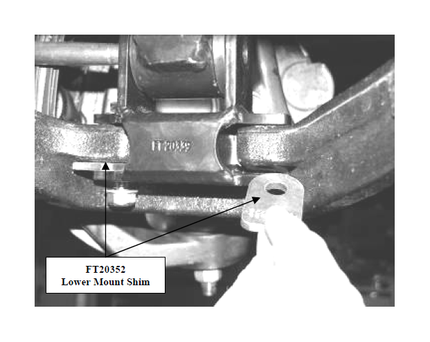
20. Locate FT20339 Lower Shock Mount, FT20352 Lower Mount Shim, and the supplied 7/16” x 2 ½” hardware. Position the mount onto the lower control arm so the flat side of the bracket will be flush with the stop on the arm. Position the shim in between the new mount and the control arm. Attach with the 7/16” hardware and torque to 50 ft lbs. Rotate the lower control arm up and attach the strut to the new mount with the provided ½” x 3 ¾” hardware and torque to 75 ft lbs. (it may be necessary to rotate the shock and extension to attach). Torque the top shock bolts to 40 ft lbs. SEE PHOTOS BELOW AND ON NEXT PAGE.
21. Locate the steering knuckle FT20276D and FT20276P. Attach the lower control arm to the knuckle using the stock hardware and torque to 70 ft lbs. Attach the upper control arm to the new knuckle using the factory hardware and torque to 35 ft lbs.
22. Reinstall the rotor and hub bearing assembly using the stock hardware and torque flange bolts to 125 ft lbs. Reinstall brake rotor and caliper. Torque caliper bolts to 30 ft lbs.
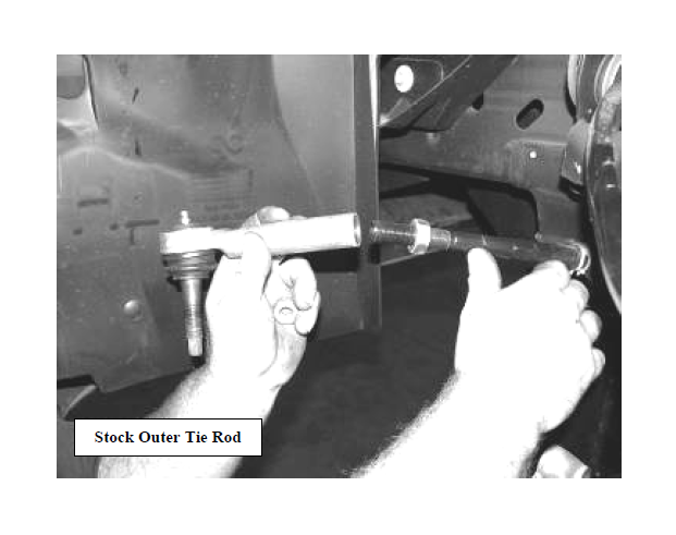
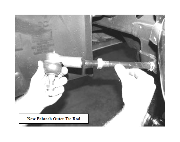
23. Locate FT20277 outer tie rods. Loosen the jam nut and remove the factory outer tie rods and discard, leaving the factory jam nut on the inner tie rod. Install the new outer tie rod onto the inner tie rod until it makes contact with the jam nut. Attach to knuckle and torque to 60 ft-lbs. (This is just a starting point; a final alignment must be performed upon completion of suspension system). SEE PHOTOS BELOW AND IN NEXT COLUMN.
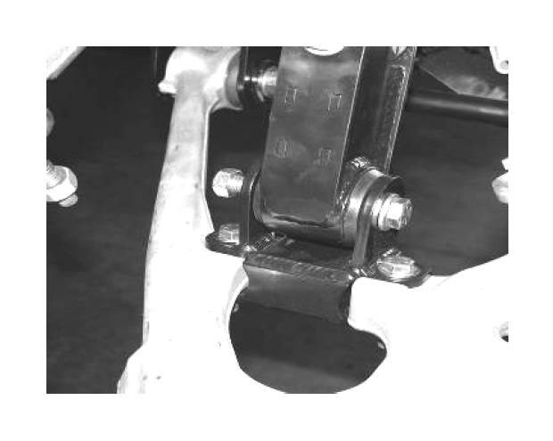
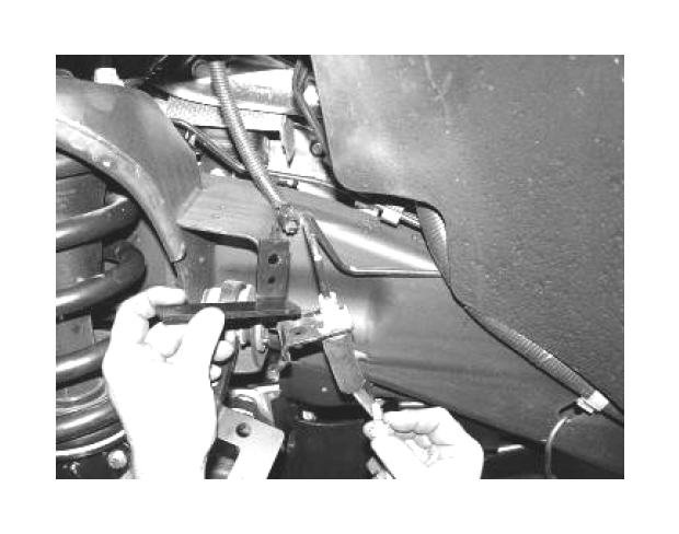
24. Locate FT20312 (Drv), FT20318 (Pass) Sway Bar Frame Bracket, and the supplied 7/16”x2 ¼” and 10mm x 30mm hardware. Position the frame bracket on the frame so that sway bar will be farther back from the suspension and attach with the 10mm hardware. Locate the factory sway bar with the factory mounts and attach to the new brackets with the 7/16” hardware and torque to 50 ft lbs. and the 10mm hardware to 25ft lbs. SEE PHOTO BELOW.
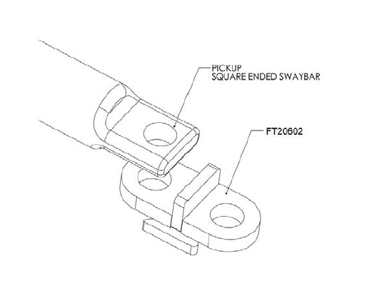
25. Locate FT20602 Sway Bar Mounts and the supplied 18mm x 50mm hardware. Position the Sway Bar Mount so that it is on the bottom of the sway bar with the SHORTER side of the mount against the stop plate end of the mount. Attach with the 18mm hardware and torque to 110 ft lbs. Locate the factory sway bar end links and attach to the new mount and the lower control arm. SEE DIAGRAM ON NEXT PAGE.
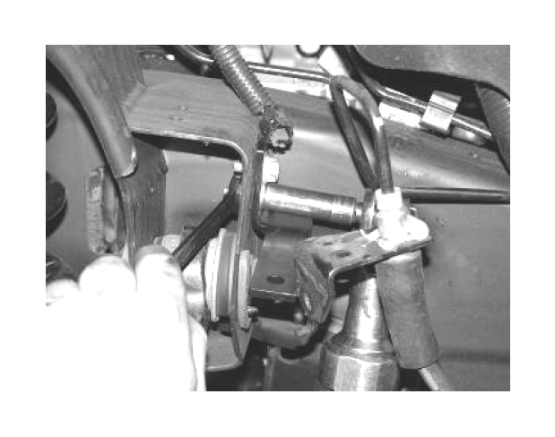
26. Locate FT20313 (drv.) FT20314 (pass) Brake Line Bracket and ¼” x ¾” hardware. Position the new bracket into the factory brake line bracket location and attach with the factory hardware and the ¼” hardware. Attach the factory brake line bracket to the new Fabtech bracket. Carefully bend the hard brake line and attach with the supplied ¼” hardware. Torque to 10 ft lbs. SEE PHOTOS BELOW AND IN NEXT COLUMN.
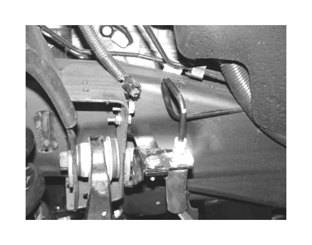
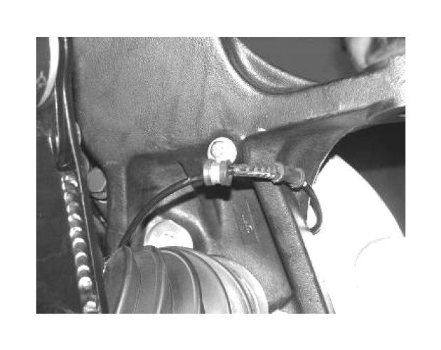
27. Re-route the brake hose and the ABS Line to the steering knuckle using the adel clamp to the back of the steering knuckle and attach with ¼” x 3/4” bolt and washer. Torque to 10 ft lbs. Route the ABS line next to the brake hose. Re-connect the ABS line to the harness in the wheel well. Using provided plastic tyraps secure line to the hose and away from the tire and wheel. SEE PHOTO BELOW.
28. Reattach the driveshaft to the differential yoke using the stock hardware and torque to 19 ft lbs.
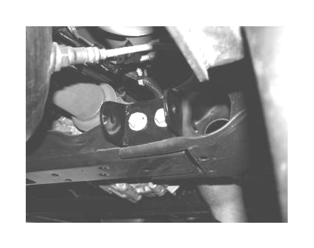
29. Locate the FT20288 Impact Strut Tube Mounts. Working from the drivers side, support the transmission crossmember and remove the two bolts that secure the crossmember to the frame. Position the new mount onto the front of the crossmember and insert the factory bolts into the new mount and then into the crossmember having the factory nut on the back of the crossmember. Torque to 75 ft lbs. SEE PHOTO ON NEXT PAGE.
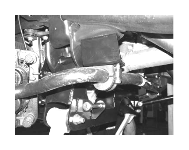
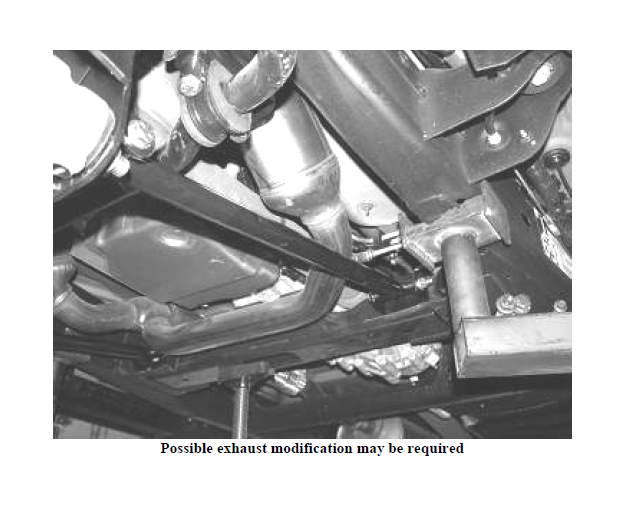
30. Locate and install the bushings into the Impact Strut bars. Attach the Impact Struts into the tabs on the back side of the lower control arm crossmember and rearward to the Impact Strut mounts using 7/16” x 3-1/2” bolts, nuts and washers from Hardware. **NOTE** MAY NEED TO MODIFY EXHAUST TUBE ON SOME MODELS. Torque to 45 ft lbs. SEE PHOTO BELOW.
31. Install front tires and wheels. Torque lug nuts to wheel manufacturer’s specifications. Check the brake and ABS lines for proper clearance from all moving items.
REAR P/U SUSPENSION INSTRUCTIONS:
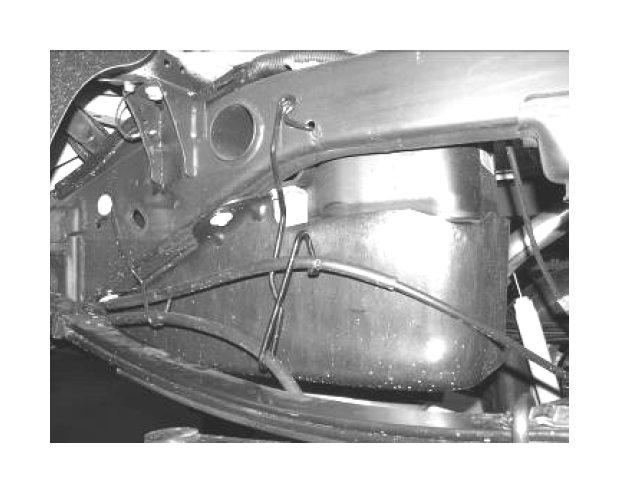
32. Jack up the rear end of the vehicle and support the frame rails with jack stands. Supporting the rear differential, remove and discard the rear shocks, u bolts and blocks. Disconnect the brake line bracket at the differential and save the hardware. Remove the ABS line clip from the top of the frame and at the axle. Remove the e-brake cable bracket on the driver’s side of the frame and save the hardware. Lower axle down slowly. Use care not to over extend the brake hose. SEE PHOTO IN NEXT COLUMN.
33. Clamp the leaf spring in the middle of the spring and remove the center bolt. Separate the springs and install the provided add a leaf with the new center bolt in a pyramid pattern smallest on the bottom graduating to the longest on top. The factory flat overload leaf should remain on the bottom of the pack. Clamp the spring and tighten the center bolt as not to leave a gap between the springs. Cut the thread of the bolt smooth with the nut. The nut should be on the top of the leaf spring pack.
34. Locate and install the rear lift blocks with the provided short center pin on the bottom of the block, to the axle. The short end of the block should face to the front of the vehicle. Using the provided U bolts, nuts and washers, align the axle, lift blocks, and springs. Torque the U-Bolts to 90 ft lbs.
35. Remove the rear bump stops from the frame. Take the factory bolts and use a die grinder with a cut off wheel and cut a ½” from the bottom. Locate FT20025 bump stop spacers and install to the factory bumpstops using the trimmed factory bolt. Use a drill with a 7/16 bit and drill out the weld nut in the frame that originally held the bumpstops in place. Install the 10mm x 25mm bolt in from the inside of the frame and attach the new bumpstop spacer. Torque the bolts to 30 ft lbs. SEE PHOTOS ON NEXT PAGE.
36. Locate FT20349 Brake Line Bracket and the supplied 5/16” hardware. Attach the new bracket to the differential and attach the brake line to the new bracket. Torque to 20 ft lbs.
37. Install new Fabtech shocks (not included with this kit) with the factory hardware and torque 65 ft lbs.
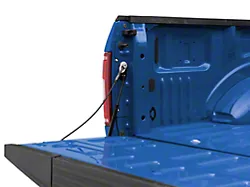
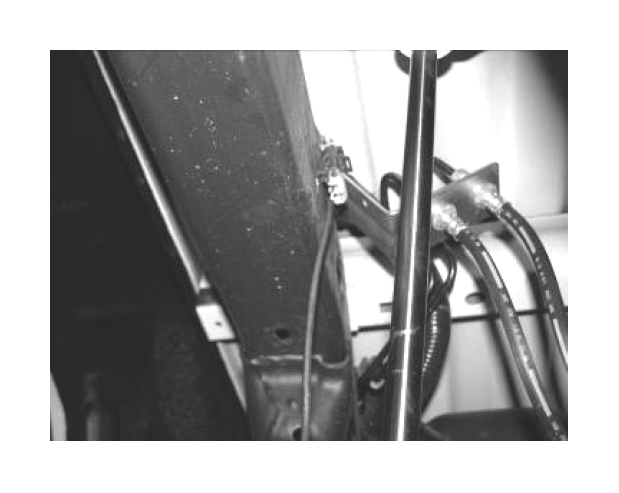
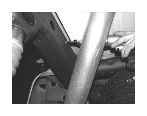
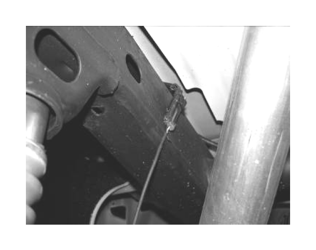
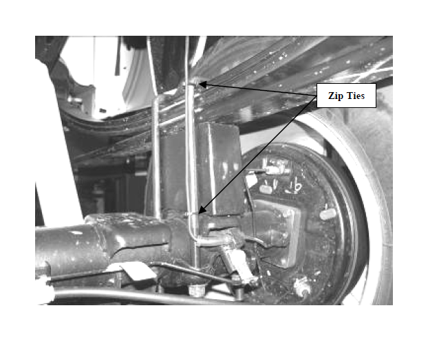
38. Working from the driver’s side, insert the previously removed upper ABS line clamp into the existing hole on the inside of the frame. Re-insert the lower ABS line clamp back into the stock location. Use two of the supplied zip ties and attach the ABS line to the U-Bolt. Keep the line taught at the block and ensure that there is enough slack in the line for full travel of the rear axle. SEE PHOTOS BELOW AND ON NEXT PAGE.
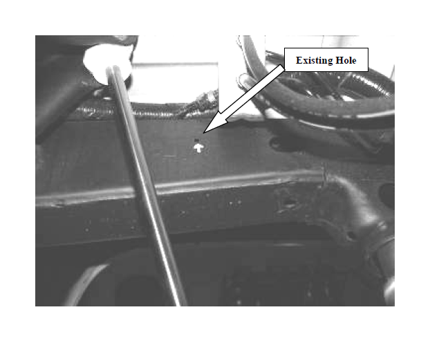
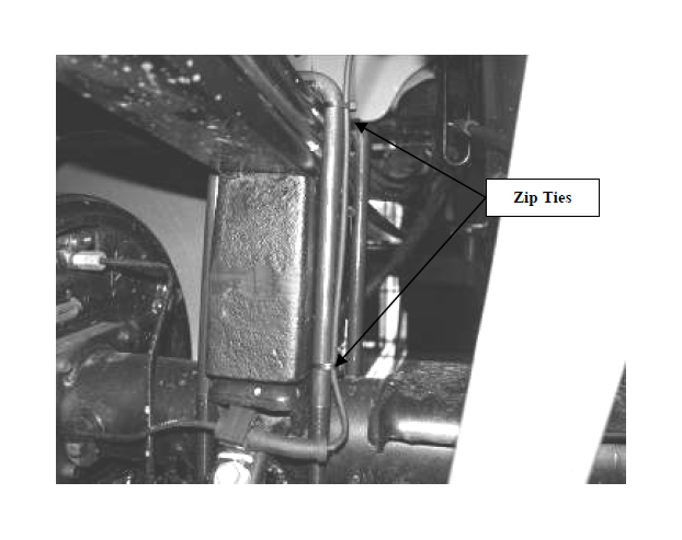
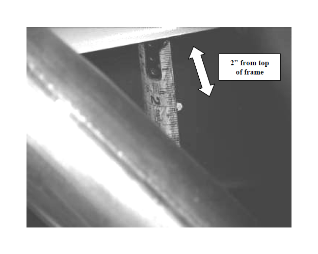
39. Working from the passenger side, locate the original line clamp hole in the top of the frame and measure 2” down the inside of the frame and drill a ¼”. Insert the previously removed upper ABS line clamp into the new hole on the inside of the frame. Re-insert the lower ABS line clamp back into the stock location. Use two of the supplied zip ties and attach the ABS line to the U-Bolt. Keep the line taught at the block and ensure that there is enough slack in the line for full travel of the rear axle. SEE PHOTOS IN NEXT COLUMN.
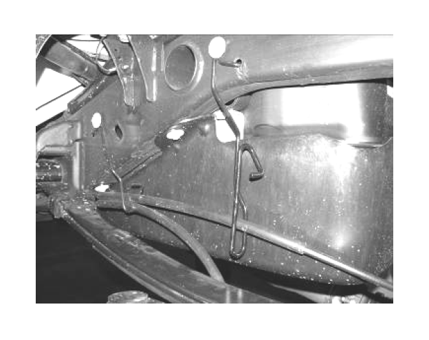
40. Remove the driver’s side E-brake cable from the previously removed bracket. Position the passenger side cable into the bottom position of the bracket where the driver’s side was originally. Re-install the bracket back into the factory location with the factory hardware. SEE PHOTO IN NEXT COLUMN.
41. Recheck all bolts for proper torque. Recheck brake hoses and lines for proper clearances.
42. Check the fluid in the front differential and fill if need with factory specification differential oil.
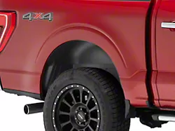
43. Install tires and wheels and torque lug nuts to wheel manufacturer’s specifications. Turn front tires left to right and check for appropriate tire clearance. Note- Some tires may require trimming of the front plastic bumper valance.
44. Check front end alignment and set to factory specifications. Re-adjust headlights.
IN ORDER TO UTILIZE THE FACTORY WHEELS AFTER INSTALLATION OF THIS SUSPENSION YOU MUST USE PROVIDED FT20300 WHEEL SPACERS. WHEEL SPACERS ARE FOR LOW SPEED OPERATION ONLY, 50 MPH AND SLOWER. WHEEL SPACERS MUST BE GIVEN TO THE END CONSUMER FOR USE WITH FACTORY SPARE TIRE