FREE 1 to 3-Day Delivery on Orders $149+ Details
How to Install Fabtech 6 in. GEN II Basic Lift System w/ Shocks on your Silverado
Installation Time
3 hours
Tools Required
- Basic Hand Tools
- Floor Jack
- Jack Stands
- Assorted Metric and S.A.E sockets, and Allen wrenches
- Torque Wrench
- Die Grinder w/ Cutoff Wheel or Reciprocating Saw

Shop Parts in this Guide
- Fabtech 6-Inch GEN II Basic Suspension Lift Kit with Shocks (14-18 2WD/4WD Silverado 1500 Double Cab, Crew Cab)
- Fabtech 6-Inch GEN II Performance Suspension Lift Kit with Dirt Logic 2.5 Coil-Overs and Shocks (14-18 2WD/4WD Silverado 1500 Double Cab, Crew Cab)
- Fabtech 6-Inch GEN II Performance Suspension Lift Kit with Dirt Logic 2.5 Reservoir Coil-Overs and Shocks (14-18 2WD/4WD Silverado 1500 Double Cab, Crew Cab)
- Fabtech 6-Inch GEN II Performance Suspension Lift Kit with Dirt Logic 4.0 Coil-Overs and Shocks (14-18 2WD/4WD Silverado 1500 Double Cab, Crew Cab)
- INSTRUCTIONS -
FRONT SUSPENSION
1. Disconnect the negative terminal on the battery. Jack up the front end of the truck and support the frame rails with jack stands. NEVER WORK UNDER AN UNSUPPORTED VEHICLE! Remove the front tires.
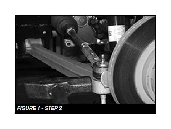
2. Working from the front of the truck, remove factory skid plate. Disconnect the tie rod ends from the steering knuckle by striking the knuckle to dislodge the tie rod end. SEE FIGURE 1
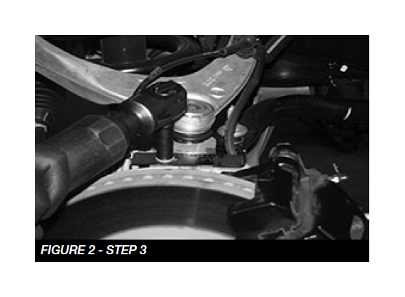
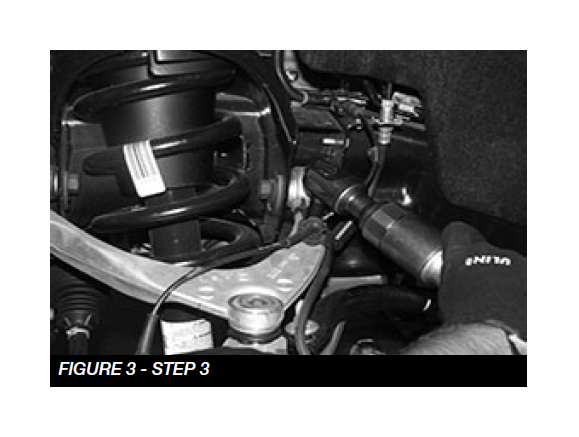
3. Remove the brake hose bracket from the steering knuckle and coil bucket, save hardware. Remove the caliper from the rotor and secure the brake caliper to the frame out of the way. DO NOT ALLOW THE BRAKE CALIPER TO HANG FROM THE HOSE. SEE FIGURES 2-3
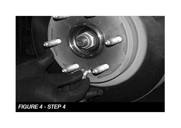
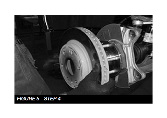
4. Remove the wheel stud clips and discard. Remove the rotor positioning screw, and remove the rotor. Put in safe place not allowing it to get damaged. Retain hardware for reinstallation. SEE FIGURES 4-5
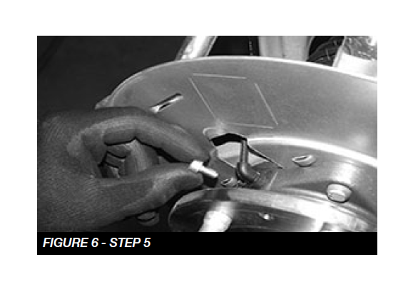
5. Remove the wheel sensor screw and carefully remove the sensor and reroute it away from the spindle. Save hardware. SEE FIGURE 6
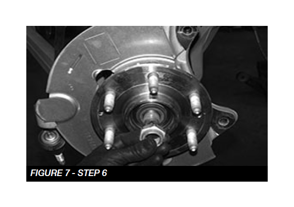
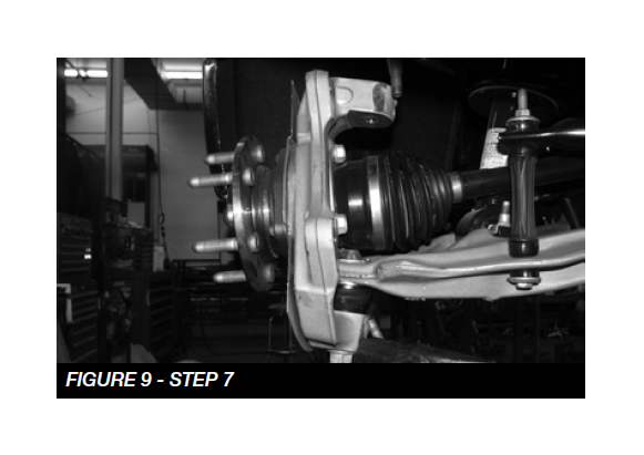
6. Remove the axle nut and washer, save for re-installation. SEE FIGURE 7
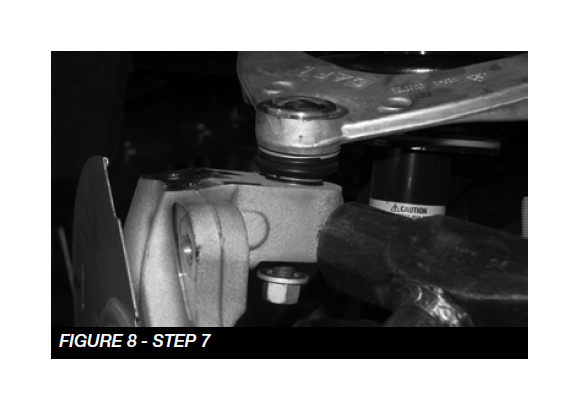
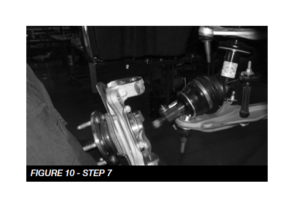
7. Loosen the upper and lower ball joint nuts. Using a large hammer, carefully strike the spindle at the ball joint to dislodge the ball joint. Use care not to hit the ball joints when removing. SEE FIGURES 8-10. Remove and save the nuts. Discard the factory spindle.
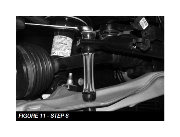
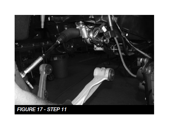
8. Remove the sway bar end link bolt and the end link save the bolt for reinstallation. SEE FIGURE 11
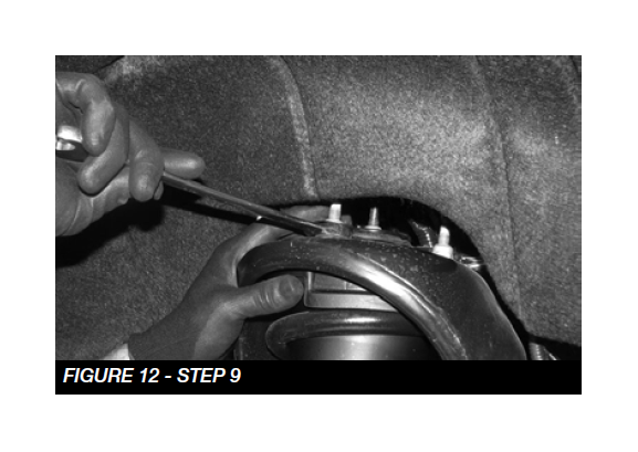
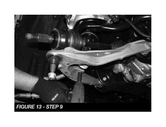
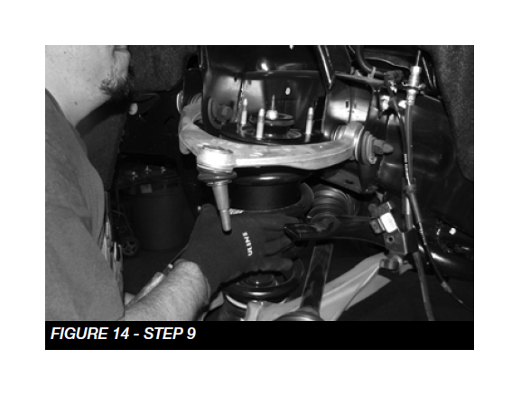
9. Remove and save the upper coilover assembly nuts, and lower bar pin bolts. Remove the coilover. NOTE: For Magna-Ride models disconnect the wire at the top of the coilover. SEE FIGURES 12-14.
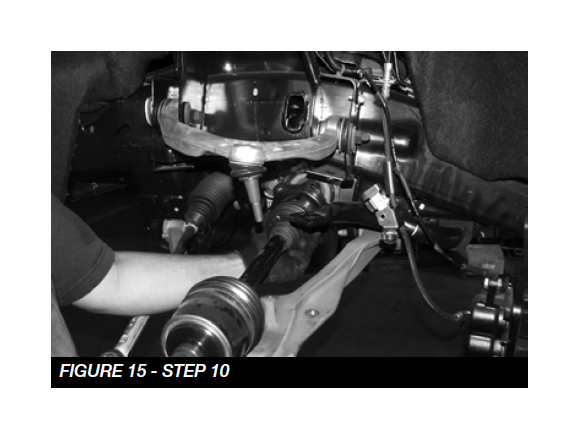
10. Remove and save the bolts attaching the axle shaft to the differential. Remove the axle shaft. SEE FIGURE 15
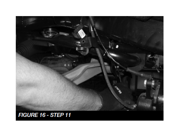
11. Loosen and remove the lower control arm bolts. Remove control arms and set aside with hardware. SEE FIGURES 16-17
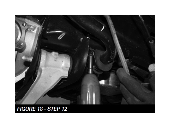
12. Remove sway bar from vehicle, discard hardware. SEE FIGURE 18
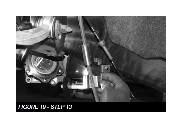
13. Remove the factory brake line bracket from the brake line. Be careful not to damage the hose. NOTE: May require cutting, be careful not to damage the hose. SEE FIGURE 19
14. Locate and remove the rear factory cross member and discard. SEE FIGURE 20

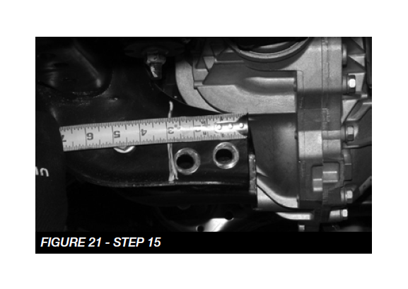
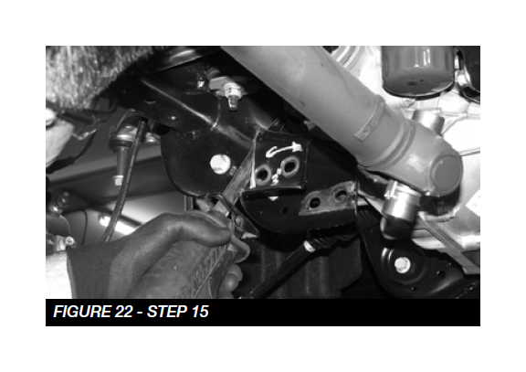
15. Locate the rear driver lower control arm mount on the frame. Measure 3” from the inside edge of the mount and mark with a paint pen. Use a reciprocating saw and cut both sides of the mount from the frame. SEE FIGURES 21-22
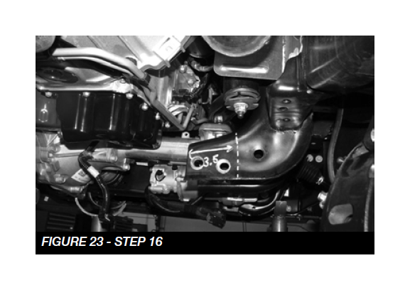
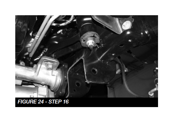
16. Locate the rear passenger lower control arm mount on the frame. Measure 3-1/2” from the inside edge of the mount and mark with a paint pen. Use a reciprocating saw and cut both sides of the mount from the frame. SEE FIGURES 23-24
17. Locate the factory front lower control arm pockets. Grind about 1/4” from both corners on both pockets. SEE FIGURES 25-26
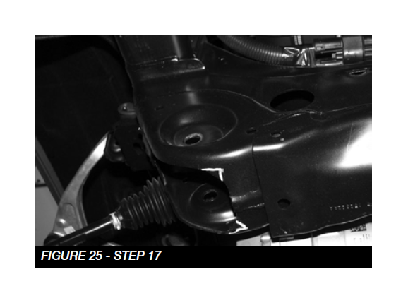
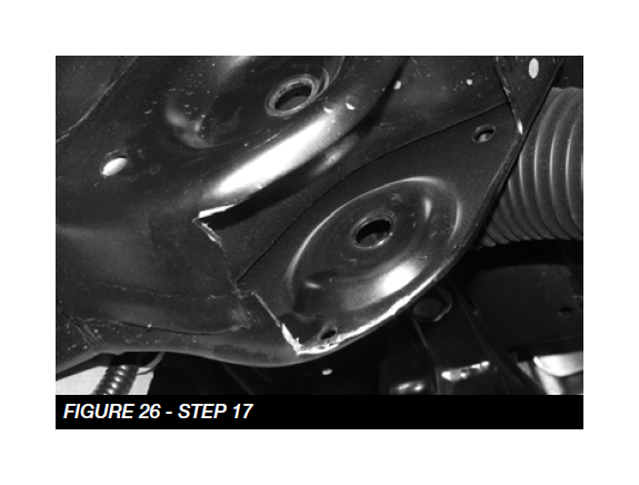
18. DUE TO VARIANCES IN EACH TRUCK, ADDITIONAL GRINDING MAY BE REQUIRED FOR PROPER FITMENT OF THE CROSS MEMBERS. USE THESE MEASUREMENTS AS A STARTING POINT AND CLEARANCE THE FRAME POCKETS AS NEEDED FOR PROPER FITMENT OF THE CROSS MEMBERS.
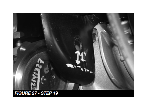
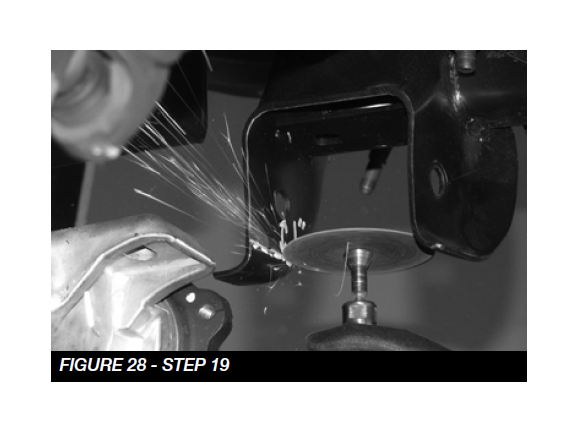
19. Locate the driver and passenger rear lower control arm pockets. On the front side of the pockets, measure and mark 1” down from the mounting hole. Cut the brackets like shown in FIGURES 27-28
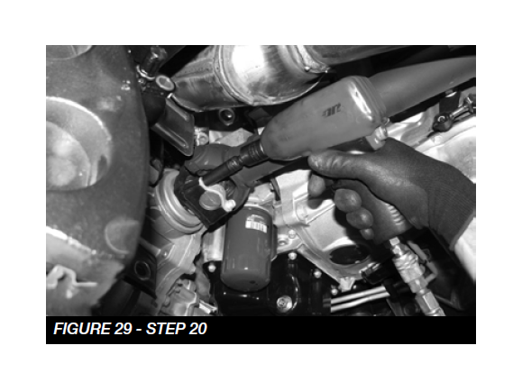
20. Disconnect the front driveshaft from the differential housing and retain bolts and u joint clamps for reinstallation. SEE FIGURE 29
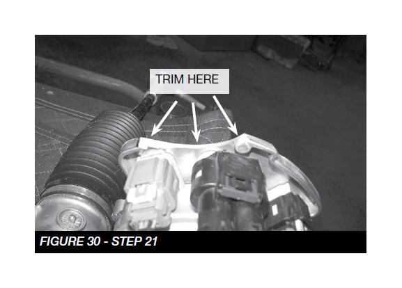
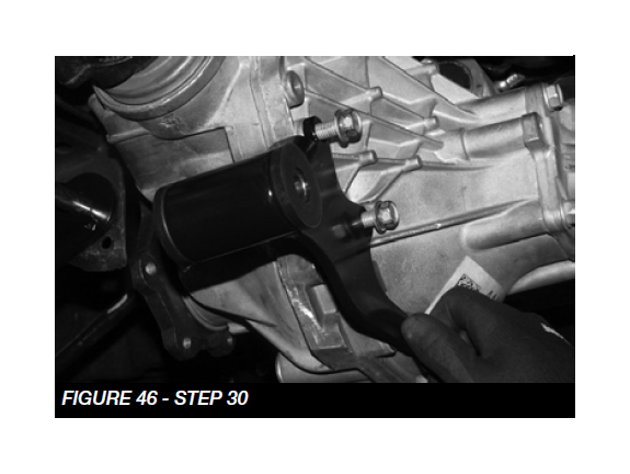
21. Unplug the steering rack harness and remove the steering rack. Due to manufacturer variances, some steering racks will need to be trimmed on the passenger side where the wiring harnesses are located. If the rack has an extended lip over the harness carefully trim a radius like shown in FIGURE 30
22. Disconnect the electrical connection (pass side) and the vacuum line (driver side) from the differential housing. Make sure the wire harness is completely detached from the housing. Carefully remove the differential and set aside. Retain hardware for reinstallation.
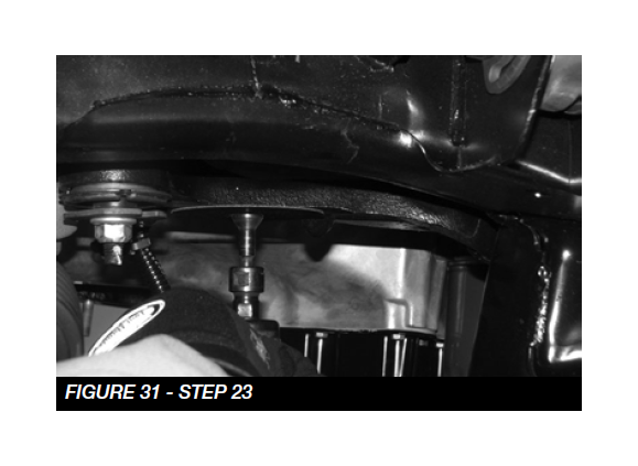
23. Locate the drivers side differential mount. The locating pin on the mount needs to be cut off. Using a die grinder with a cut off wheel, cut the pin flush with the bracket. SEE FIGURE 31
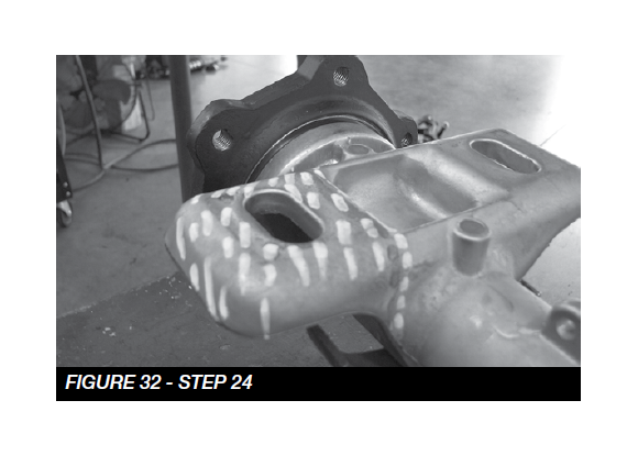
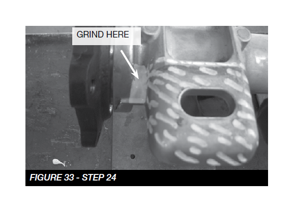
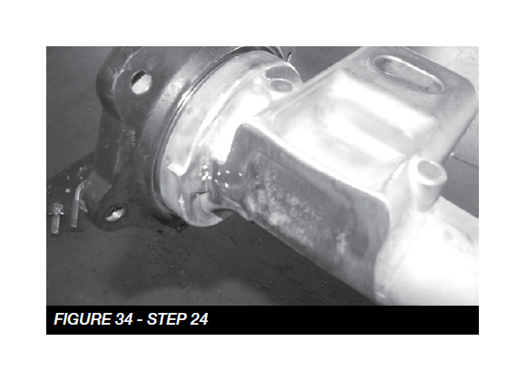
24. Locate the passenger side front mounting tab on the differential. Cut the front tab straight off and sand to a smooth finish. The end should be flush with the axle housing. NOTE: More sanding may be required due to manufacturer variances. SEE FIGURES 32-34
Note: Grind a flat spot on the axle (approx. 1/8” deep) just to the side of the mounting tab. SEE FIGURE 33. This is to prevent the sterring rack and differential from making contact.
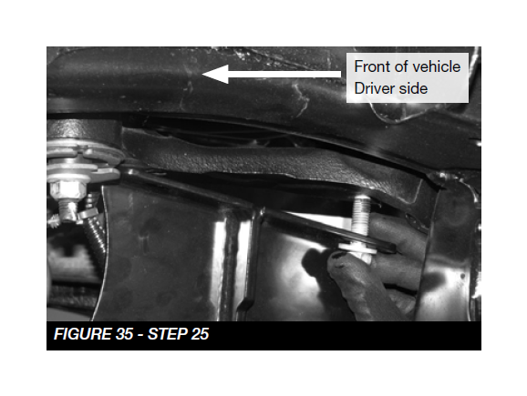
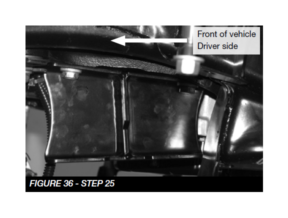
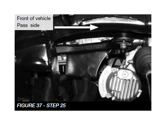
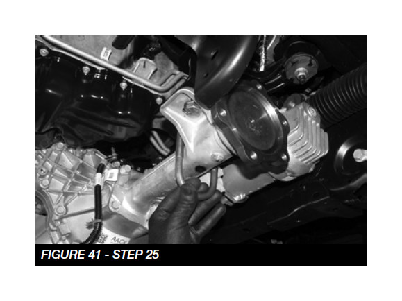
25. Locate FT20647 (driver) and FT20648 (pass) differential drop brackets and factory hardware. Install the brackets to the factory mounts with the taller part of the bracket towards the front of the vehicle. SEE FIGURES 35-37 Torque to 100 ft-lbs.
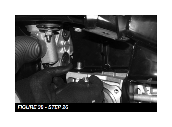
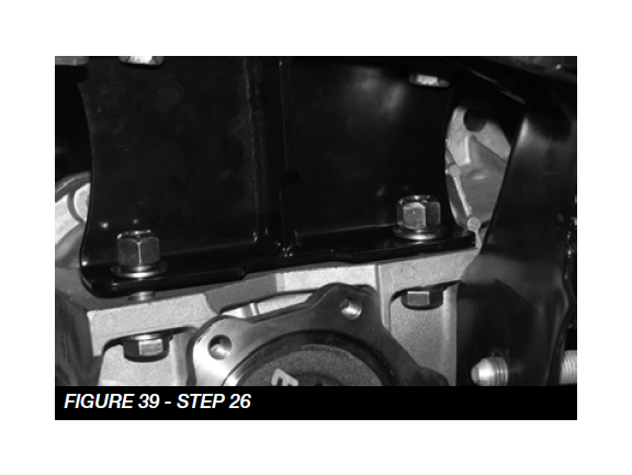
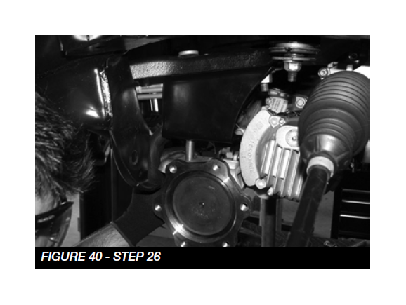
26. Locate the Differential drop bracket hardware. (driver) 1/2”-13 x 1-3/4” bolt, washers, and nuts. (Pass) 9/16”-12 x 1-3/4” bolt, washer, and nut, FT757U (ubolt) and 1/2” washers and nuts. Using a transmission jack, install the differential into the vehicle with the provided hardware, leave loose at this time. SEE FIGURES 38-41
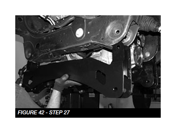
27. Reinstall the steering rack and plug all harnesses back in. Locate and install FT20637BK (front crossmember) into the factory lower control arm pockets using the stock hardware. Leave loose at this time. SEE FIGURE 42
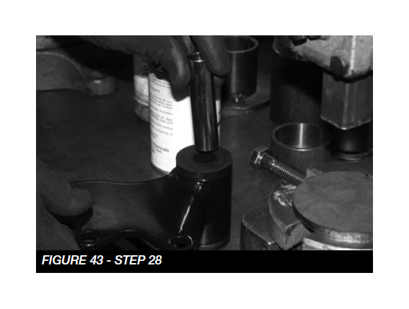
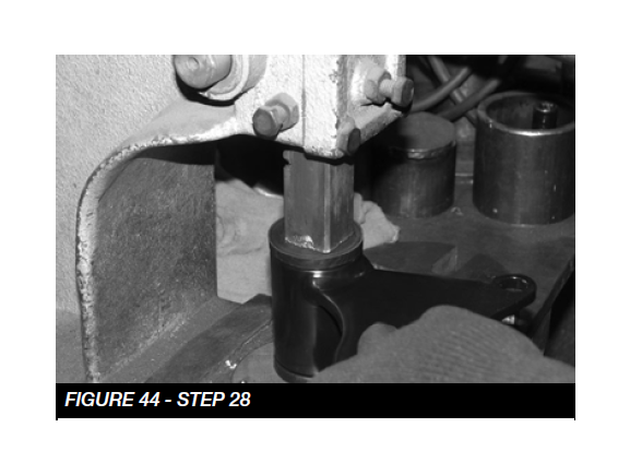
28. Install FT90085 (bushing kit) into FT20655 (rear diff support) SEE FIGURES 43-44
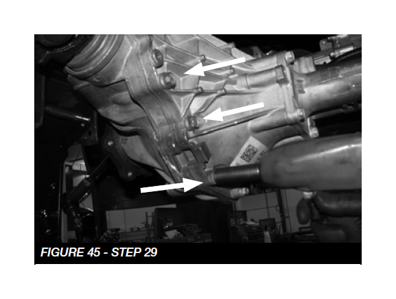
29. Remove the 3 factory differential housing bolts and discard. SEE FIGURE 45
30. Install the FT20365 (rear diff support bracket) on the differential using the provided M10-1.5 X 60mm bolts, washers and thread lock. Torque to 58 ft-lbs. SEE FIGURE 46
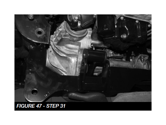
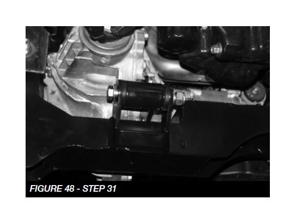
31. Locate and install FT20638BK (rear crossmember) using the provided 5/8”-11 X 5-1/2” bolts, washers, and nuts, leave loose at this time. Locate the rear diff support hardware 9/16”-18 X 4-1/2” bolt, washers and nut. Install the hardware and leave loose at this time. SEE FIGURE 47-48
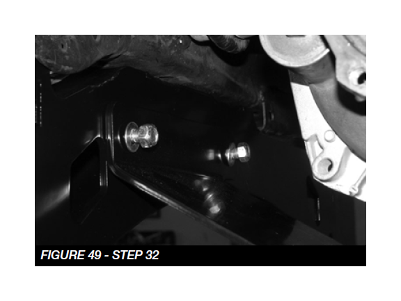
32. Locate FT20657BK (front skid plate) using the provided hardware, install the skid plate by using the 7/16”-14 x1- 1/2” bolts, washers and nuts to the front crossmember. Torque to 83 ft-lbs. Use the 1/2”-13 x 1-1/2” bolt, washer and nut on the rear crossmember. Torque to 127 ft-lbs. SEE FIGURE 49
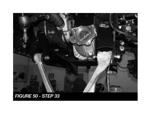
33. Reinstall the lower control arms using the provided 5/8”-11 X 4-1/2” bolt, washers and nut for the front pocket. Use the 5/8”-11 X 5-1/2” bolt, washers, and nut for the rear pocket. Leave loose at this time. SEE FIGURE 50
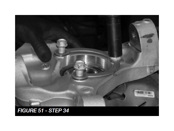
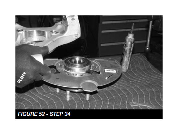
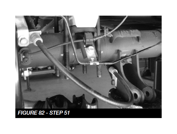
34. Locate the factory spindle. Disassemble the factory knuckle from the hub assembly by removing the 3 bolts. Discard knuckle washer. SEE FIGURES 51-52
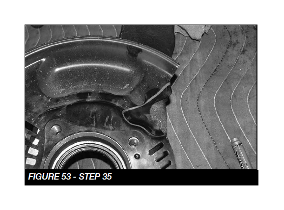
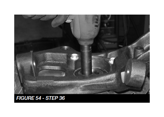
35. The dust shield on the hub assembly needs to be trimmed to clear the new Fabtech spindle. Refer to FIGURE 53-54. Repeat for passenger side.
36. Locate FTS20641D, FTS20640D, FTS20642D or FT20736D (Driver Knuckle), assemble the new spindle on the hub assembly. Use thread lock on the factory hardware and torque to 125 ft-lbs. Repeat on passenger side using the corresponding knuckle. SEE FIGURE 54
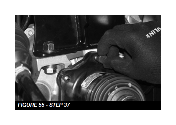
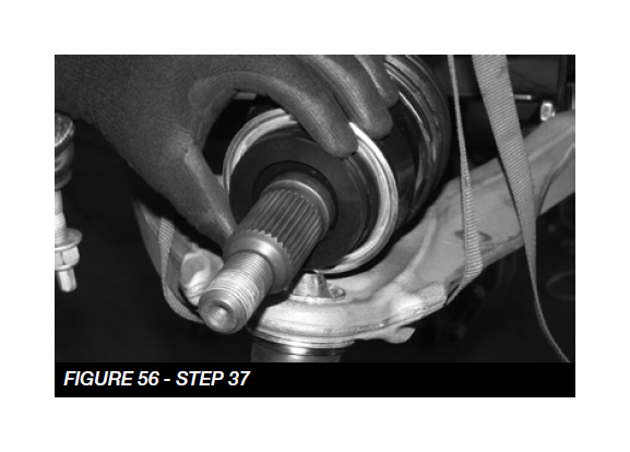
37. Locate the drivers side axle shaft, factory hardware and FT20664 (Axle Shaft Spacer).Using thread lock install the Axle shaft to the differential SEE FIGURE 55, Torque to 55 ft-lbs. Install FT20664 (Axle Shaft Spacer) onto the axle SEE FIGURE 56.
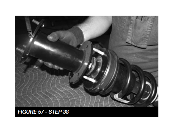
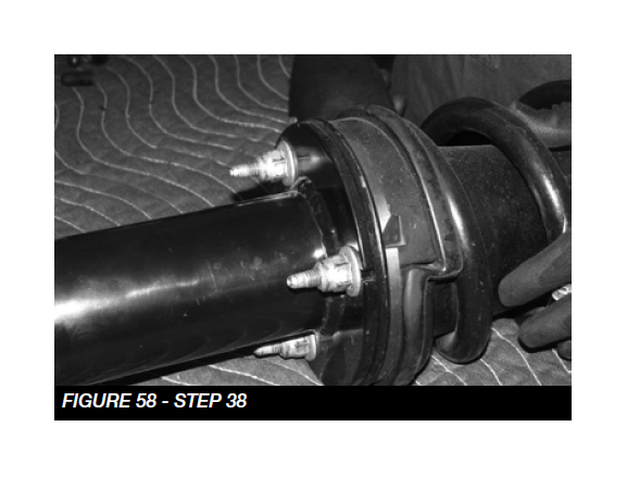
38. NOTE: For Dirt Logic Coilovers skip to step 38. Locate the factory drivers side coilover assembly and FT20667BK (Driver side shock extension). NOTE: When installing on vehicle equpped with Magna-Ride. Route the wire up through the inside of the new Fabtech spacer before installing the factory nuts. Using the thread lock assemble the two with the factory hardware. Torque to 58 ft-lbs. SEE FIGURE 57-58 Repeat for Passenger side.
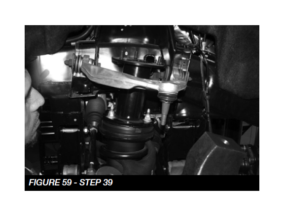
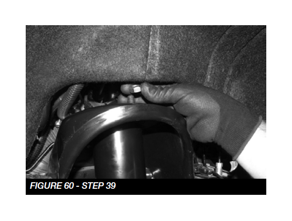
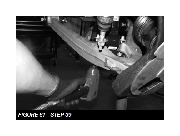
39. Install the coilover assembly into the top mount using the provided 7/16” hardware. Torque to 83 ft-lbs. Then, use the factory hardware to assemble the lower control arm to the coilover. Torque to 100 ft-lbs SEE FIGURES 59-61
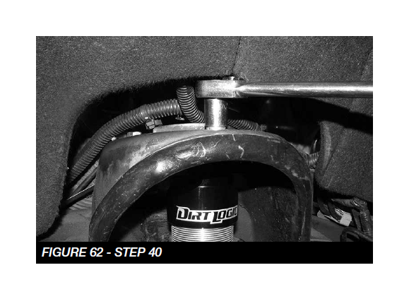
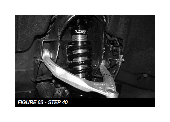
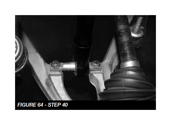
40. For Dirt Logic Coilovers use the supplied 3/8” hardware for the top mount, and 7/16” hardware for the lower mount. When installing the coilover, it will offset towards the rear of the vehicle. SEE FIGURES 62-64.
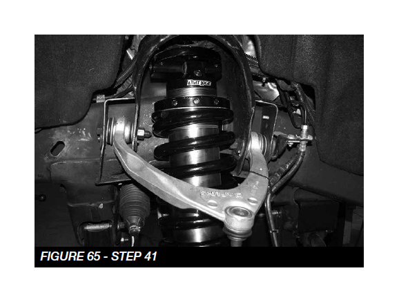
41. If installing the Dirt Logic 4.0 Coilover. It will install the same as in Step 39. SEE FIGURE 65
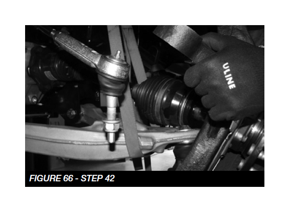
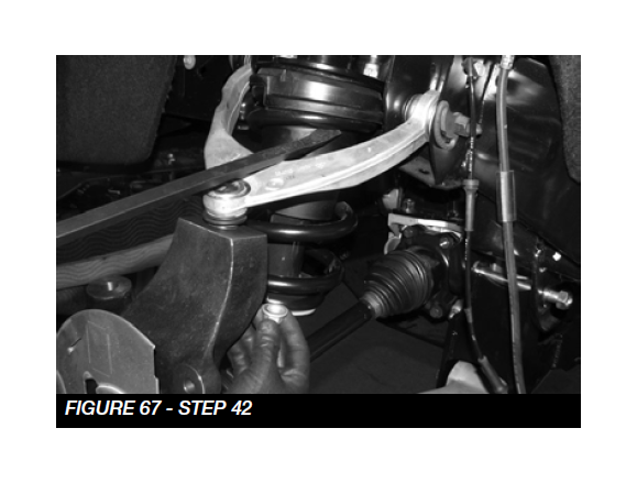
42. Install the new spindle onto the lower control arm ball joint while inserting the axle end through the hub assembly SEE FIGURE 66 Torque to 83 ft-lbs. Finally, connect the upper control arm to the spindle. SEE FIGURE 67. Torque the upper ball joint to 58 ft-lbs, and the lower ball joint to 70 ft-lbs.
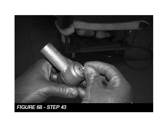
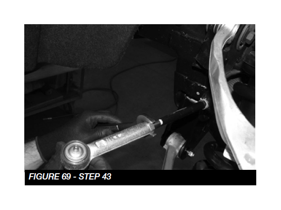
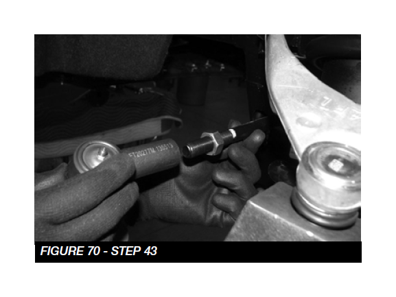
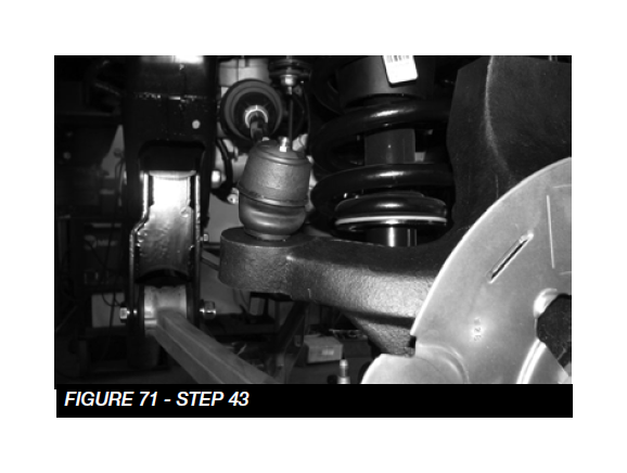
43. Locate the FT20277 (Outer Tie Rod), install the zerk fitting that is provided. SEE FIGURE 68. Loosen the jam nut and remove factory tie rod end, leaving the factory jam nut in place, install the FT20277 until it makes contact with the jam nut. Attach the new tie rod end to the spindle with the supplied nut and torque to 40 ft-lbs. Then, tighten the jam nut. SEE FIGURE 68-71. NOTE: IF USING 18” WHEELS, THE EXCESS THREAD ON THE BOTTOM OF THE LOWER BALL JOINT WILL NEED TO BE CUT OFF.
NOTE: Make sure to grease the new tie rod end ball joints.
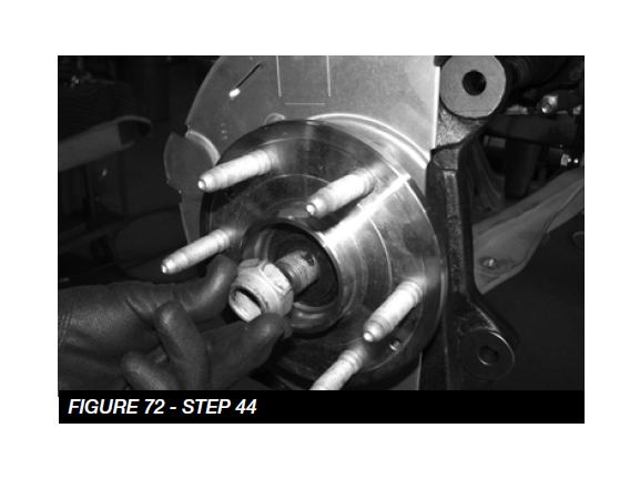
44. Locate and install the factory hub assembly washer and nut using the provided thread lock. Torque to 150 ft-lbs SEE FIGURE 72
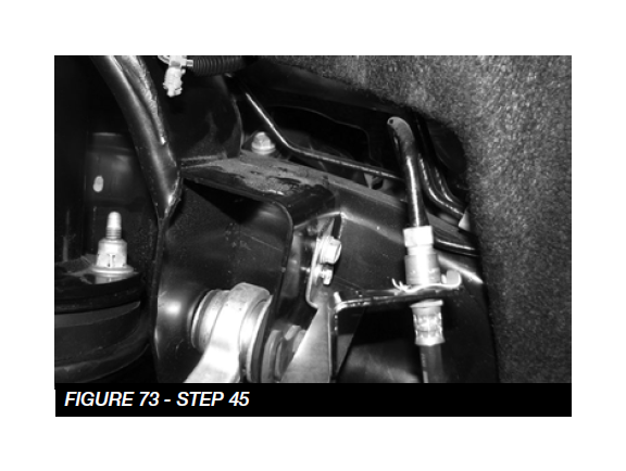
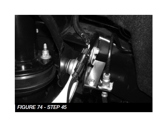
45. Locate FT20313 (Driver), FT20314 (Pass) brake line bracket and the provided 1/4”-20 x 1” bolts, washers and nuts. Position the new bracket into the factory brake line bracket location and attach with the factory hardware and the 1/4” hardware. Attach the factory bracket to the new Fabtech bracket. Carefully bend the hard brake line and attach with the supplied 1/4” hardware. Torque to 10 ftlbs. SEE FIGURES 73-74
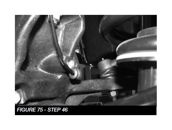
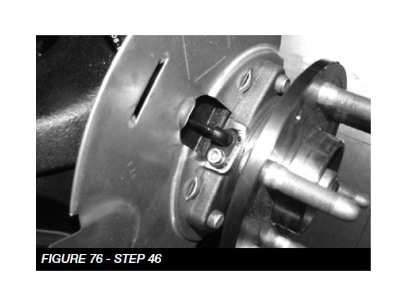
46. Re-route the brake hose and the ABS line to the steering knuckle. Secure the ABS line to the back of the knuckle using the provided clamp and 1/4” bolt and washer. Torque to 10 ft-lbs. Re-connect the ABS line into the hub assembly and torque to 10 ft-lbs. Use the provided black zip ties to mount the brake line in a safe location. SEE FIGURES 75-76
47. Proceed with torquing all bolts and nuts. Differential bracket bolts torque to 127 ft-lbs. Cross member bolts torque to 254 ft-lbs, rear differential bracket torque to 100 ft-lbs.
48. Re-install the front driveshaft to the differential with the factory hardware and torque to 50 ft-lbs.
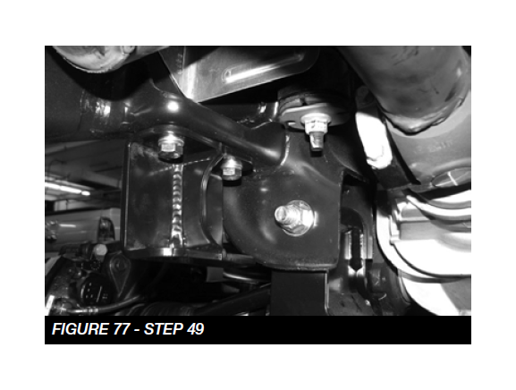
49. Locate FT20658BK (sway bar drop brackets), and M10- 1.5 x 30 bolts and washers. Install the new brackets with the flat side towards the outside of the vehicle. Torque to 58 ft-lbs. SEE FIGURE 77
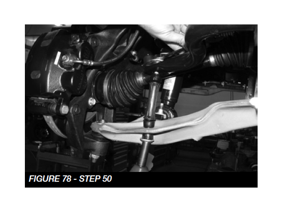
50. Install the factory sway bar using the provided 3/8”-16 x 1-1/2” bolts, washers and nuts. Torque to 52 ft-lbs. Install the factory sway bar links with the factory hardware and torque to 58 ft-lbs. SEE FIGURES 78
REAR SUSPENSION
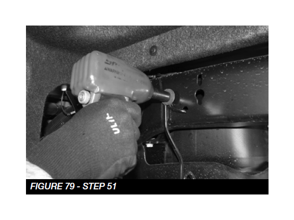
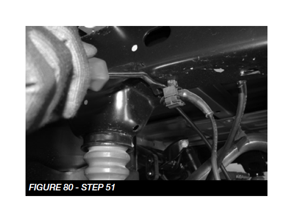
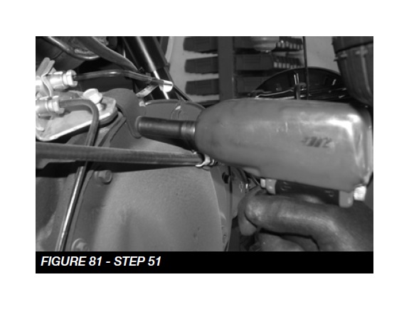
51. Jack up the rear end of the vehicle and support the frame rails with jack stands. Supporting the rear differential, remove and discard the rear shocks, u-bolts and blocks. Disconnect the brake line bracket at the differential and save the hardware. Remove the ABS line clip from the top of the frame and at the axle. Remove the e-brake cable bracket on the drivers side of the frame and save the hardware. Lower axle down slowly. Use care not to over extend the brake hose. SEE FIGURES 79-81
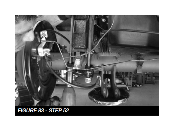
52. Locate FTBK5 (5” Block), FT1500U-3 (Ubolts) and 9/16” Hardware. Install the blocks with the new hardware, the short end of the block should be facing the front of the vehicle. Torque to 184 ft-lbs. SEE FIGURE 83
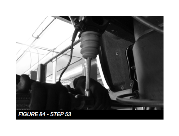
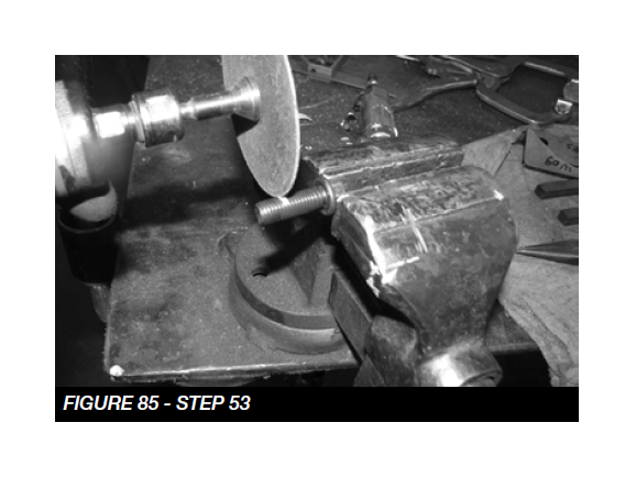
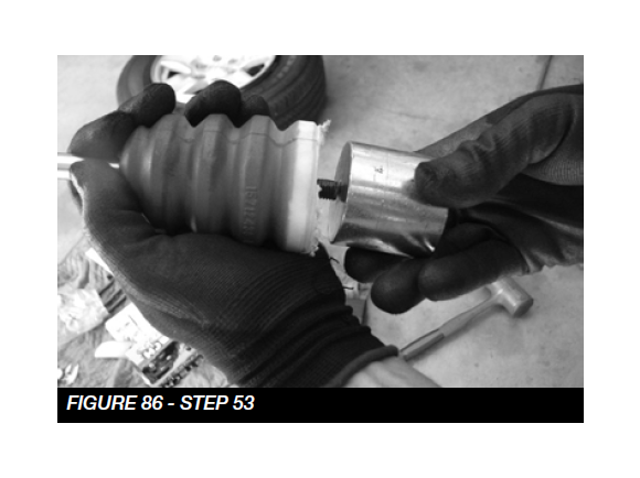
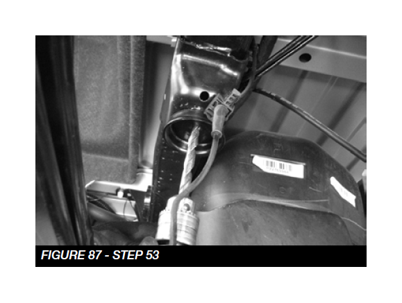
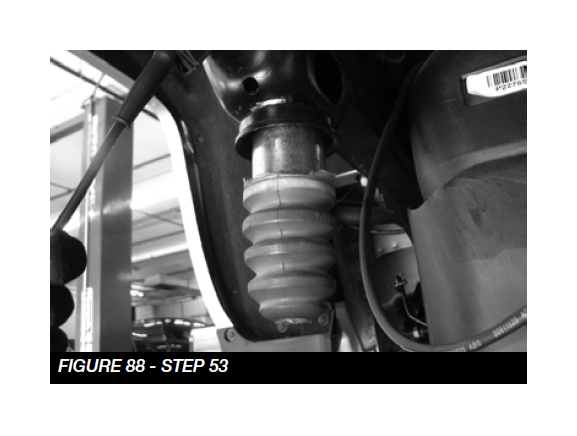
53. Remove the rear bump stops from the frame. Take the factory bolts and use a die grinder with a cut off wheel to cut 1/2” from the end. Locate FT20025 bump stop spacers and install to the factory bumpstops using the trimmed factory bolt. Use a drill with a 7/16” bit and drill out the weld nut in the frame that originally held the bumpstops in place. Install the 10mm x 25mm bolt and washer from the inside of the frame and attach the new bumpstop spacer. Torque the bolts to 58 ft-lbs. SEE FIGURE 84-88
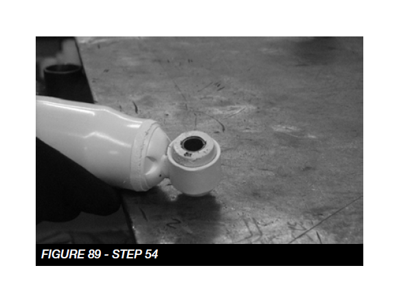
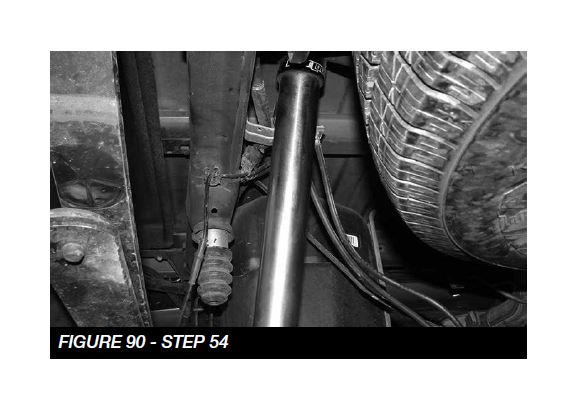
54. Locate FTS7240 (Performance Shock) or FTS810561 (Dirt Logic 2.25 Black Shock). Insert the bushings and sleeves into the ends, and install. Torque to 65 ft-lbs. SEE FIGURES 89-90
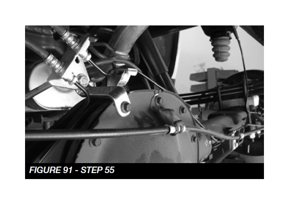
55. Locate FT20349 (Brake Line Bracket) and the supplied 5/16”-18 x 1” bolt, washers and nut. Attach the new bracket to the differential using the factory bolt. Then, attach the brake line assembly to the new fabtech bracket using the supplied 5/16” hardware. Torque to 29 ft-lbs. SEE FIGURE 91
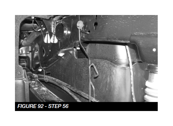
56. Remove the drivers side E-brake cable from the previously removed bracket. Position the passenger side cable into the bottom position of the bracket where the drivers side was originally. Re-install the bracket into the factory location with the factory hardware. SEE FIGURE 92
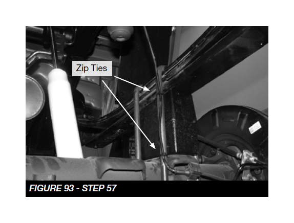
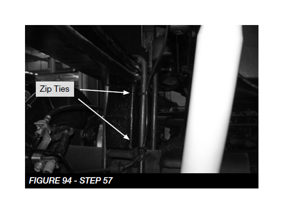
57. Using the supplied black zip ties, secure both ABS lines to the inside part of the u bolt. Allow some slack when securing them all the way. SEE FIGURE 93-94
58. Install tires and wheels and torque lug nuts to wheel manufacturer’s specifications. Turn front tires left to right and check for appropriate tire clearance. Note - Some oversized tires may require trimming of the front bumper & valance.
59. Check front end alignment and set to factory specifications. Readjust headlights.
60. Recheck all bolts for proper torque.
61. Recheck brake hoses, ABS wires and suspension parts for proper tire clearance while turning tires fully left to right.
62. Check the fluid in the front and rear differential and fill if needed with factory specification differential oil. Note - some differentials may expel fluid after filling and driving. This can be normal in resetting the fluid level with the new position of the differential/s.
63. Install Driver Warning Decal. Complete product registration card and mail to Fabtech in order to receive future safety and technical bulletins on this suspension.
Vehicles that will receive oversized tires should check ball joints, uniballs and all steering components every 2500-5000 miles for wear and replace as required.
RE-TORQUE ALL NUTS, BOLTS AND LUGS AFTER 50 MILES AND PERIODICALLY THEREAFTER.