FREE 1 to 3-Day Delivery on Orders $149+ Details
How to Install Fabtech 4 in. Uniball Upper Control Arm System w/ Dirt Logic Coilovers & Shocks
Installation Time
3 hours
Tools Required
- Basic Hand Tools
- Floor Jack
- Jack Stands
- Assorted Metric and S.A.E sockets, and Allen wrenches
- Torque Wrench
- Die Grinder w/ Cut Off Wheel

Shop Parts in this Guide
- INSTRUCTIONS -
FRONT SUSPENSION
1. Disconnect the negative terminal on the battery. Jack up the front end of the truck and support the frame rails with jack stands. NEVER WORK UNDER AN UNSUPPORTED VEHICLE! Remove the front tires.
2. Starting on the driver side of the truck, remove the bolt attaching the brake line tab to the spindle.
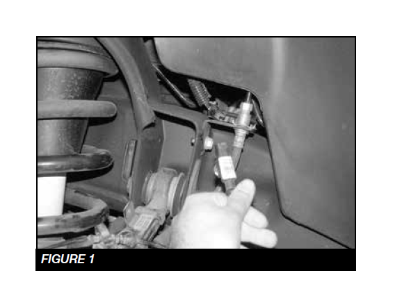
3. Follow the wheel speed sensor wire from frame rail plug. Separate the wire from the upper control arm. SEE FIGURE 1
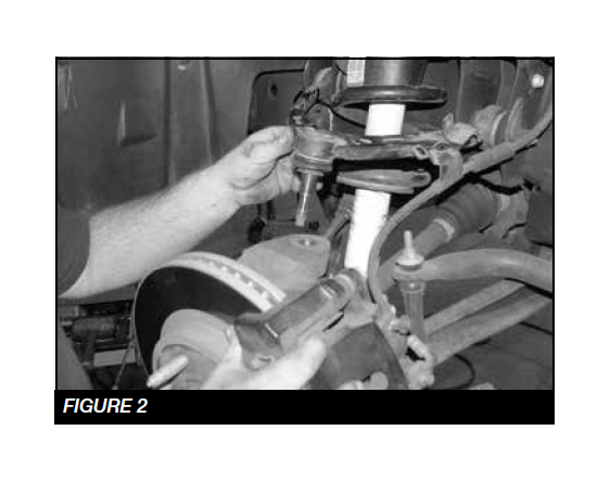
4. Remove the nuts securing the tie rod and upper arm ball joints to the spindle. Separate both joints from the spindle by striking the knuckle with a large hammer next to each joint on the knuckle to dislodge. SEE FIGURE 2
5. Remove the factory coil over and save.
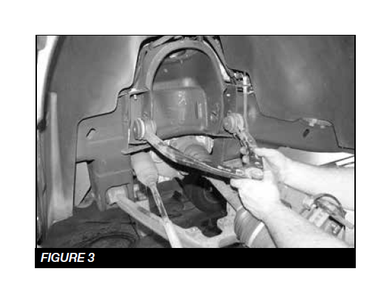
6. Mark the location of the alignment cams on the frame of the upper control arm pocket. Remove the upper control arm from the vehicle and save the factory hardware. SEE FIGURE 3
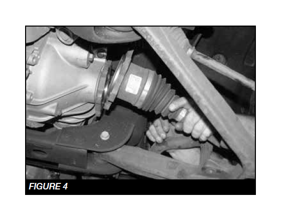
7. Remove the factory CV shaft from the differential drive flange. Retain Hardware. SEE FIGURE 4
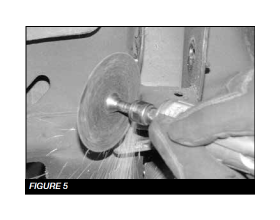
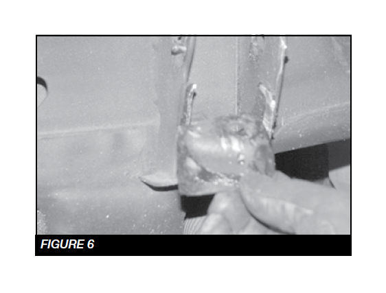
8. Using a die grinder remove the factory droop stop off the control arm pocket. SEE FIGURES 5-6
9. Using a die grinder, partially cut the brake line bracket. This will allow the bracket to be bent and removed from the brake line. Be careful not to damage brake hose.
• Repeat steps 2-9 on passenger side.
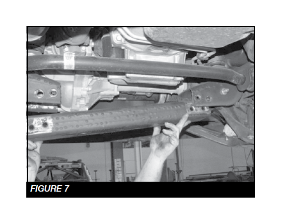
10. Remove the factory rear cross member and retain factory hardware. SEE FIGURE 7
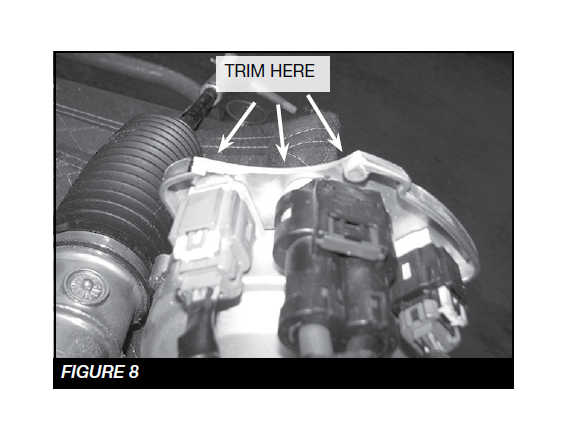
11. Due to vehicle variances, the steering rack will need to be removed and trimmed on the driver side where the wiring harnesses are located. SEE FIGURE 8
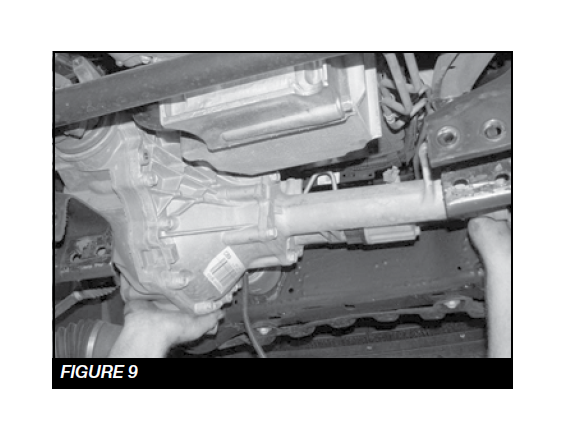
12. Disconnect the drive shaft from the front differential solenoid wiring. Disconnect the differential vent tube and remove the diff. Retain Hardware. SEE FIGURE 9
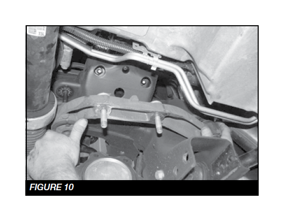
13. Locate the factory passenger side diff mount and remove. Retain Hardware. SEE FIGURE 10
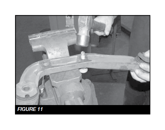
14. Remove the factory studs from the differential mount and discard the differential mount. SEE FIGURE 11
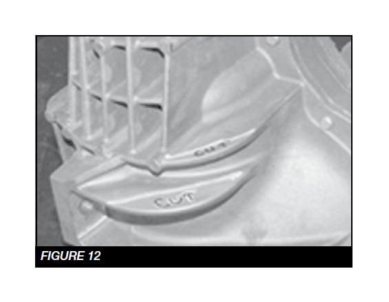
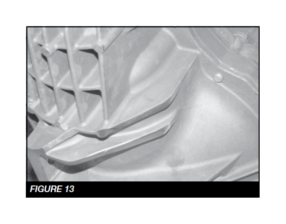
15. Locate the factory diff and cut off the driver side rear cooling fins. SEE FIGURES 12-13
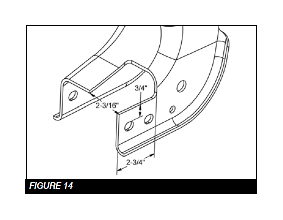
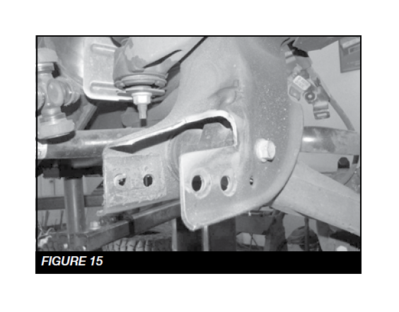
16. Locate the factory rear driver lower control arm pocket / cross member mount. Using a die grinder remove the material shown in the diagram below. SEE FIGURES 14-15
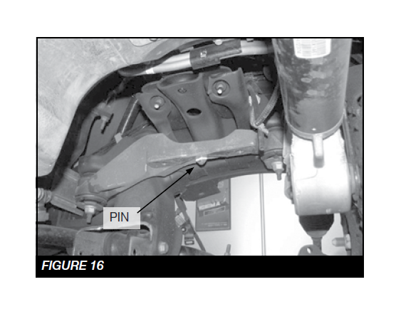
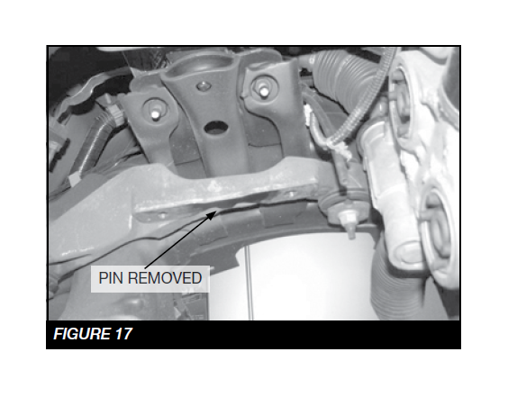
17. Locate the factory driver side Diff mount. Using a die grinder remove the locating pin from the mount. SEE FIGURES 16-17
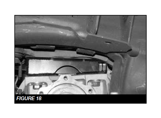
18. Locate the FT20625 driver side diff mount and the FT20626 passenger side diff mount. Starting on the driver side, remount the diff with two M12-1.75 x 70mm bolts. Torque to 100 ft-lbs SEE FIGURE 18
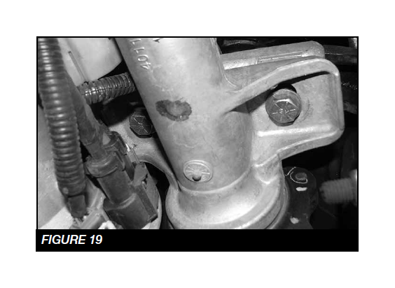
19. Using the passenger side differential mount, two ½”-13 x 4” bolts, nuts and washers, mount the passenger side of the differential. NOTE: Run the bolts from the bottom up . Torque the 1/2” bolts to 127 ft-lbs. SEE FIGURE 19
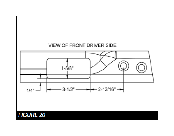
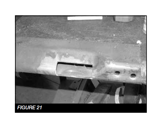
20. Locate the factory rear cross member. Using a die grinder remove the material from the driver side. SEE FIGURES 20-21
21. Reconnect the drive shaft, differential vent tube and solenoid with factory hardware. Torque to 17 ft-lbs.
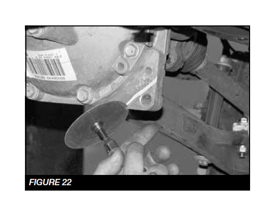
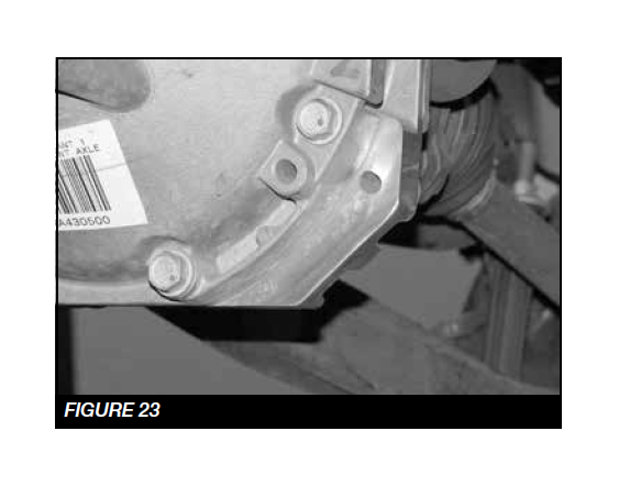
22. Cut the front of the differential to clear the new skid plate. SEE FIGURES 22-23
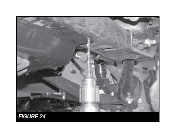
23. Locate the FT20627BK skid plate and the two 3/8”- 16x3/4” self taping bolts. Mount the skid plate to the factory front cross member using two of the factory front bolts. With front of the skid plate mounted, use the back two holes in the skid plate for a drill guide. Drill two 5/16” pilot holes and install the two 3/8” self taping bolts. Torque to 21 ft-lbs. Be careful not to over torque. SEE FIGURE 24
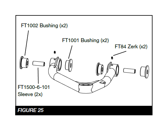
24. Locate the Fabtech driver’s side control arm FT20585BK, two FT1002 bushings, two FTS1001 bushings, two grease zerks FT84, and two sleeves FT1500-6-101.
25. Install all these components in the control arm barrels. SEE FIGURE 25
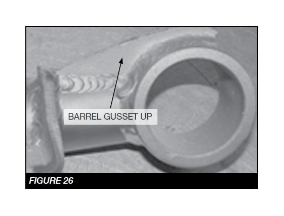
26. Install the new Fabtech upper control arm in the factory upper control arm pockets using the factory hardware at the previously marked alignment cam location. When installing the arm on the truck, make sure the barrel gussets are facing up. Torque to 160 ft-lbs. SEE FIGURE 26
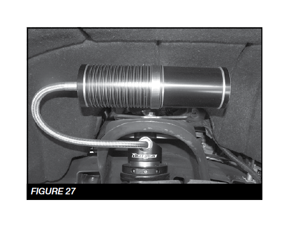
27. If installing Dirt Logic coilover, FTS810152 or FT820282D & P, do so at this time using hardware provided with that shock. When installing the Fabtech coilover the coilover should be offset towards the front of the truck. NOTE: See figure 27 for resi mount orientation. Otherwise, continue with Step 29 with the factory shock.
28. Locate the factory coil over and remove the sheet metal nut from the lower bar pin.
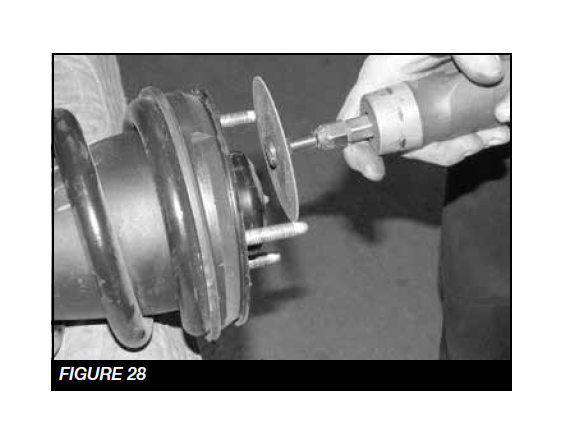
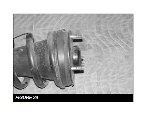
29. Cut a 1/4” off the studs on the top side of the coil over. SEE FIGURES 28-29
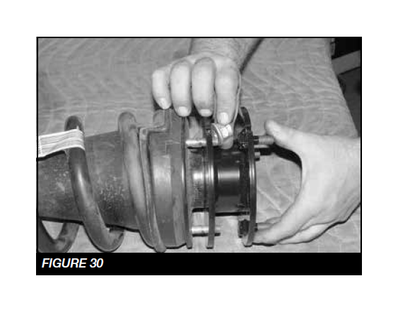
30. Install the FT20560BK coil spacer using the factory nuts and torque to 58 ft-lbs. SEE FIGURE 30
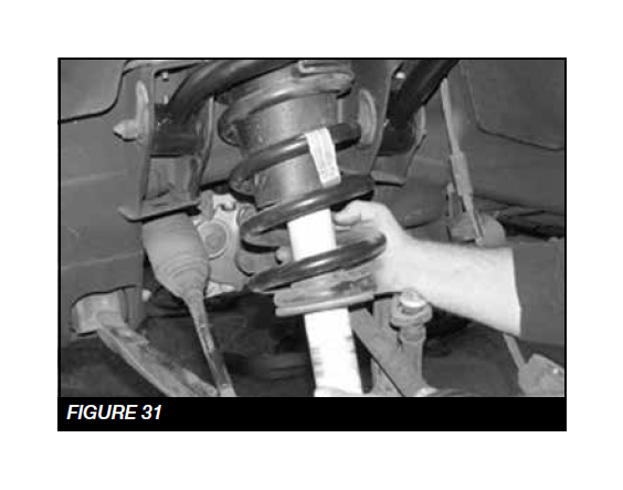
31. Locate the three 7/16” nylock nuts and install the coil over into the upper shock mount. Leave loose at this time. SEE FIGURE 31
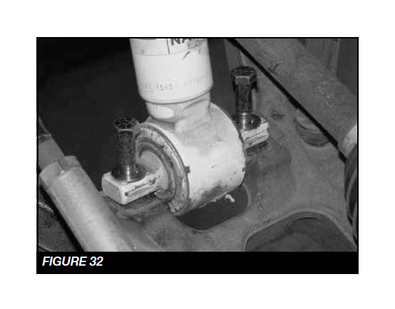
32. Locate the two 7/16”-14 x 2-1/4” bolts, nuts and washers and install the lower bar pin mount onto the lower control arm. Torque the upper and lower bolts to 83 ft-lbs. SEE FIGURE 32
33. Locate FT94502 Uniball adapter pin, and two FT147 uniball misalignment spacers.
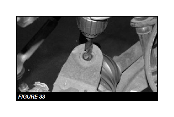
34. Using a 1/2” drill, chase out the upper ball joint tapper on the factory knuckle. SEE FIGURE 33
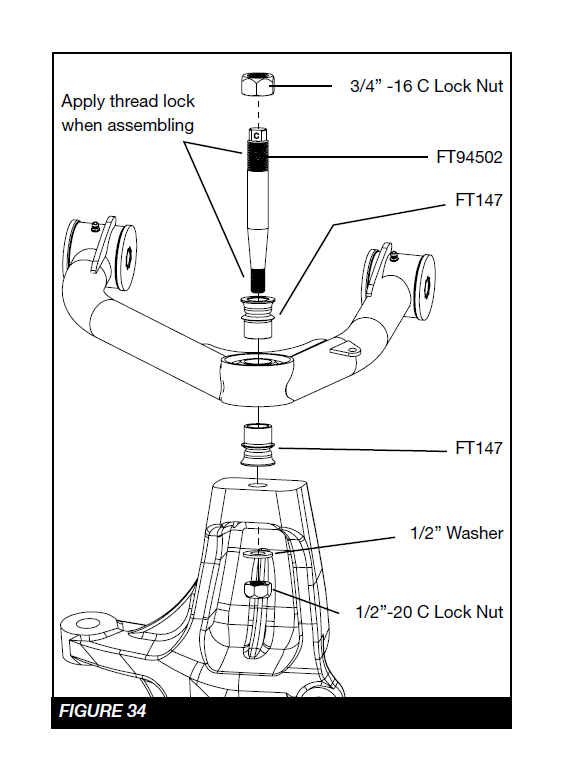
SEE FIGURE 34 FOR STEPS 35 - 39
35. Insert the uniball pin into the factory knuckle upper ball joint taper. Install the 1/2 -20 lock nut with thread lock compound and flat washer onto the bottom side of the pin. This will lock the pin into the knuckle. Torque to 127 ft-lbs.
36. Install one FT147 uniball misalignment spacer on to the pin.
37. Swing the control arm down, slide the pin into the uniball on the control arm seating the lower FT147 spacer in the control arm.
38. Install the upper FT147 uniball misalignment spacer onto the pin.
39. Install the 3/4” -16 lock nut on the top side of the pin with thread lock compound and torque to 150 ft-lbs.
40. Reinstall the CV shaft and torque to 58 ft-lbs.
41. Locate Factory brakeline and wheel speed sensor wire.
42. Install the FTCLAMP on top of the spindle to hold the wheel speed sensor wire. SEE FIGURE 34
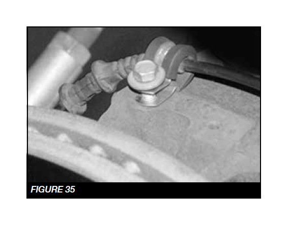
43. Attach the brakeline to the small tab on the control arm using the FTCLAMP, 1/4”-20 x 1” bolts, nuts and washers. SEE FIGURE 35
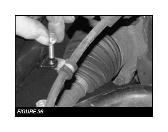
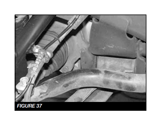
44. Reconnect the wheel speed sensor and zip tie to the brake line. SEE FIGURE 36-37
45. Repeat steps 25-44 on the passenger side of the vehicle where applicable.
REAR SUSPENSION
46. Locate the FTBK15 blocks and the four FT1500U u-bolts. With the stock u-bolts removed and the rear axle clear of the leaf spring, make sure the block will fully seat onto the leaf spring and the spring pad of the rear axle housing with the wide end of the block to the rear of the vehicle. On the leaf spring make sure the center pin head will seat fully into the hole in of the block allowing the top surface of the block to rest against the leaf spring. Install the new u-bolts with washers and nuts from the FT916H hardware kit and torque to 184 ft-lbs.Note – The Vehicle’s stance will be level with the Fabtech block. To achieve a higher rear stance stack both factory and Fabtech blocks. NOTE: For FTS21157 install FTBK3 (3” Block).
47. Install rear shocks using FTS7333 Performance shocks, FTS6333 Stealth Shocks or FTS810152 Dirt Logic shocks with factory hardware. Torque to 100 ft-lbs.
48. Install tires and wheels and torque lug nuts to wheel manufacturer’s specifications. Turn front tires left to right and check for appropriate tire clearance. Note - Some oversized tires may require trimming of the front bumper & valance.
49. Check front end alignment and set to factory specifications. Readjust headlights.
50. Recheck all bolts for proper torque.
51. Recheck brake hoses, ABS wires and suspension parts for proper tire clearance while turning tires fully left to right.
52. Check the fluid in the front and rear differential and fill if needed with factory specification differential oil. Note - some differentials may expel fluid after filling and driving. This can be normal in resetting the fluid level with the new position of the differential/s.
53. Install Driver Warning Decal. Complete product registration card and mail to Fabtech in order to receive future safety and technical bulletins on this suspension.
Vehicles that will receive oversized tires should check ball joints, uniballs and all steering components every 2500-5000 miles for wear and replace as required.
RETORQUE ALL NUTS, BOLTS AND LUGS AFTER 50 MILES AND PERIODICALLY THEREAFTER.