FREE 1 to 3-Day Delivery on Orders $149+ Details
How to Install Amp Research PowerStep Running Boards on your Silverado
Installation Time
3 hours
Tools Required
- Safety goggles
- Measuring tape
- Flat blade screwdriver
- Phillips head screwdriver
- Right angle drill
- 1/8” drill bit
- 3/16” drill bit
- 9/32” drill bit
- 21/64” drill bit
- 17mm socket
- 13 mm socket
- 10 mm socket
- 7 mm socket
- T 20 Torx driver
- Ratchet wrench and extension
- 13mm end wrench
- Wire crimpers
- Wire stripper / cutter
- Vise grip pliers
- Corrosion inhibiter
- 3/16” hex key wrench (allen wrench)
- 5mm hex key wrench (allen wrench)
- 4mm hex key wrench ( allen wrench )
- Electrical tape
- Weather proof caulking (silicone sealer)

Shop Parts in this Guide
INSTALLATION GUIDE
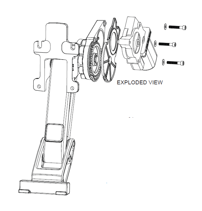
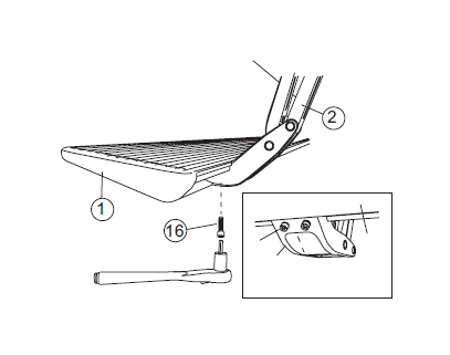
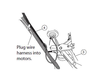
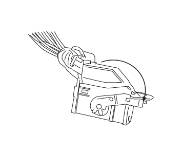
Attaching motor to linkage assembly
The motors must be attached to the linkage assemblies before continuing the
installation process.
CAUTION: HANDLE WITH CARE.
To ensure our customers receive all components with full integrity, we pack the motors separate from their linkage assemblies. This requires that the installer position and fasten the motor before continuing with the install. Please follow the instructions below and handle the assembly carefully.
CAUTION: Dropping the assembly or any excessive impact MAY cause damage to the motor.
Instructions:
1. Position the gear cover in place as shown if not already in place.
2. Seat motor into position on the three mounting bosses. This may require an adjustment of the gear by moving the swing arms.
3. After seating into place, fasten the motor with the three motor mount screws with 4mm Hex Head. Tighten screws to 36 in-lbs (4N-m). Do not over torque.
Exploded View
1
Steps 1-3 for Heavy Duty Trucks only! For all other vehicles skip to Step 4.
HD - Short Bed: Remove forward most brake cable guide.
HD - Long Bed: Remove first and third brake cable guide.
2. Install replacement brake cable guides.
3
HD - Long Bed: Install plastic brake cable guide in forward hole of rear body mount.
4
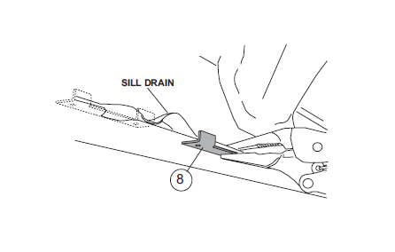
Rear linkage assembly. Template position for Tahoe and Yukon shown in hidden lines.
Clamp drill template about 1/16” forward of the rearmost sill drain.
Tahoe and Yukon: Clamp Template 1/8” behind second rearmost sill drain.
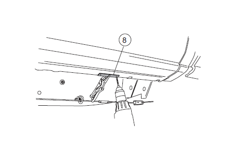
5
With drill template secured with vise grips, drill 1/8” starter holes. Remove template and drill holes to 21/64”.
6
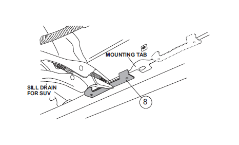
Front linkage assembly. Template position for SUV driver side shown in hidden lines.
Clamp drill template to pinch weld about 1/8” behind the forward most mounting tab. Then repeat Step 5.
SUV’s: On driver side only, clamp template 1/8” in front of forward most mounting tab.
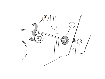
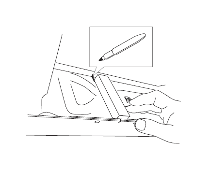
7
CAUTION: Remove step plates on inside of cab and move vehicle
wire harnesses out of the way before drilling in Steps 8 & 9.
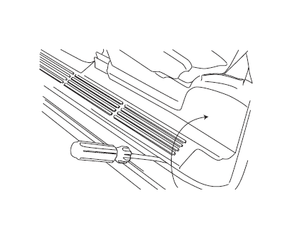
Use a straight edge to make a vertical line centered between drilled mounting holes.
8
READ THE ABOVE CAUTION NOTE!
Center the upper support mount and drill 1/8” starter holes, then remove mount and drill 3/16” holes. Drill through first layer of sheet metal only. Attach with #14 sheet metal screws.
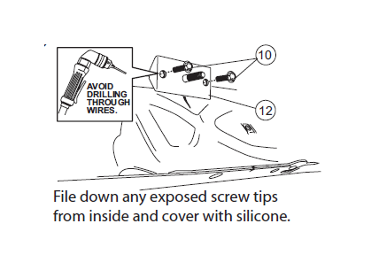
9
READ CAUTION NOTE AT TOP OF PAGE!
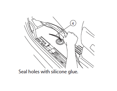
Repeat Steps 7 & 8 for rear mount. Drill through first layer of sheet metal only. This mount support will mount partially behind frame support and will require only one sheet metal screw.
File down any exposed screw tips from inside and cover with silicone.
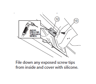
10
Mount linkage assembly and upper bracket and finger tighten all fasteners.
IMPORTANT NOTE:
For Truck and HD Avalanche: The motorized linkage assembly goes to the front location on the drivers side and to the rear location on the passenger side.
For SUV & 1500 Avalanche: The motorized linkage assembly goes towards the front on both sides.
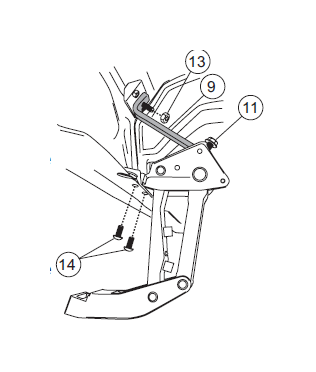
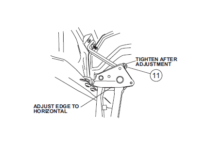
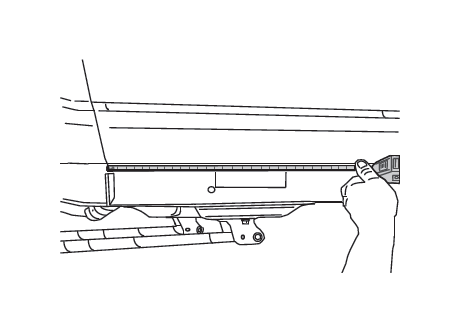
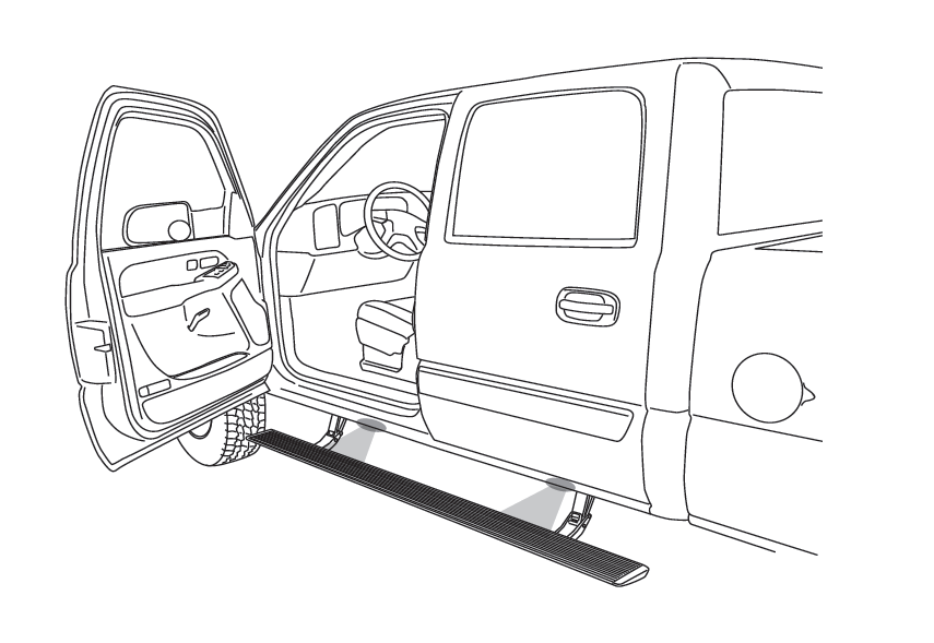
11
Slide mounting T-nut into position. Mount board and tighten fasteners to 10 ft-lbs. Align the end of the board with the rear edge of the back door.
12
Tighten button head fasteners and upper nut to 16 ft-lbs. Then adjust the bottom edge to horizontal and tighten hex bolt to 16ft-lbs.
13
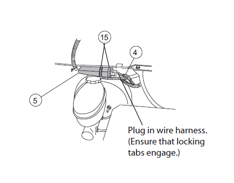
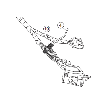
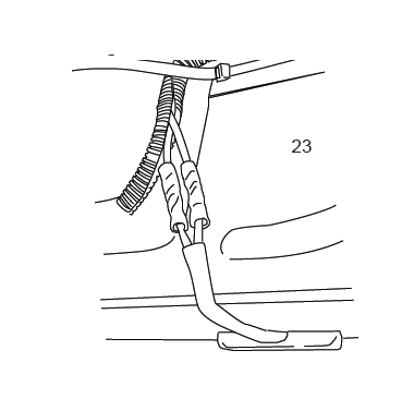
Using the two 11” cable ties, mount controller to factory wire conduit above brake booster on drivers side of truck.
Plug in wire harness. (Ensure that locking tabs engage.)
14
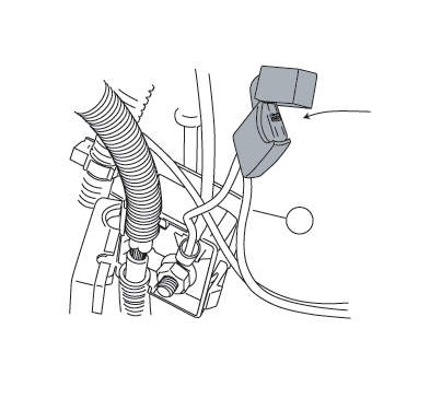
Remove power fuse. Attach power lead RED wire to positive lead in the junction box. CAUTION: Do not ground wrench when engaged with nut.
Attach ground lead to junction box mounting bracket. (See Step 15 for Diesel Engine grounding location)
15
Diesel Models only! Using supplied Hex Head Screw connect ground to air compressor mounting bracket.
16
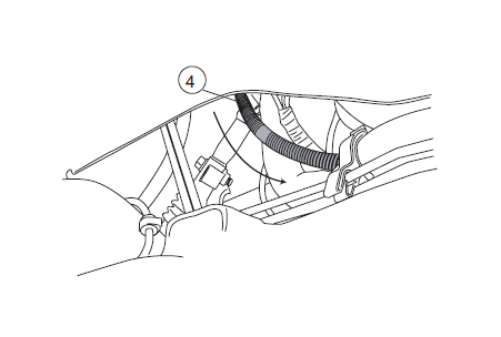
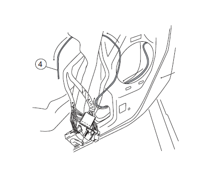
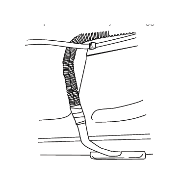
Route long end of wire harness above engine and down through passenger side wheel well. Zip tie harness to cowling clips on fire wall. Route short end down drivers side.
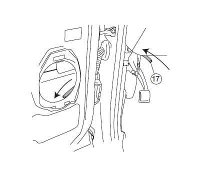
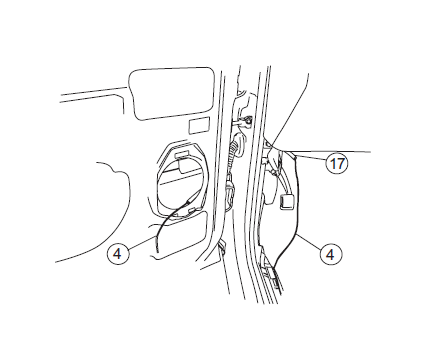
17
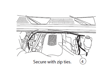
Route wire harness along the frame. Secure with zip ties.
18
Poke hole through rubber grommet near front door on underside of floor panel with small phillips screwdriver. Push both wires through hole. (See Step 20 for passenger side notes.)
19
IMPORTANT: Steps 21 and 22 are for Crew Cabs and SUV’s only. Light blue and Green wires will not be used otherwise. See end of install sheet for 1999-2002 model year wiring
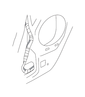
Pop off the threshold cover with screwdriver and remove the kick panel. The panel will slide out from under the seat after fasteners give way.
20
Pull up the carpet and thread both wires through the floor panel (same steps on passenger side EXCEPT drill 9/32” hole in metal and add rubber grommet).
21
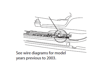
On Crew Cab’s and SUV’s carefully remove wire wrap. On drivers side find the LIGHT BLUE wire with BLACK STRIPE. On the passenger side find GREEN wire with BLACK STRIPE rear of the “T” junction where wires cross under the front seat).
See wire diagrams for model years previous to 2003.
22
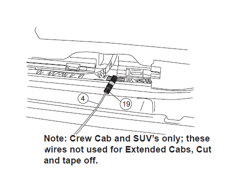
Using supplied Posi-Taps™ splice shorter trigger wire into wire found in step 21.
Note: Crew Cab and SUV’s only; these wires not used for Extended Cabs, Cut and tape off.
23
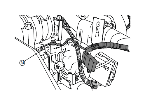
Remove plastic trim on door near mirror attachment.
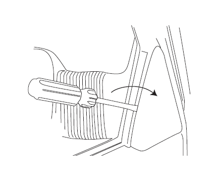
24
To remove door, first pry off door lock tab. Remove door bolts.
25
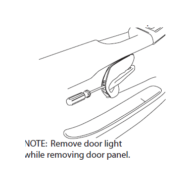
Pry off door handle plate and any remaining panel fasteners. Then remove door panel.
NOTE: Remove door light while removing door panel.
26
Pull back the door weather guard. Pry off speaker and unplug. Thread plastic tube through accordion.
27
Feed longer wire of Step 20 through tube into door and pull out plastic tube on door side.
28
Route wire along harness going to switch plate.
29
Using supplied Posi-Taps™ splice trigger wire into door ajar wire (Driver side: Gray with Black Stripe; Passenger side: Black with White Stripe). The trigger wires will attach to the connector with a cam-release lever.
30
Secure all wires with zip ties and electrical tape.
32
Make sure that plug lever is fully opened before reinstalling. Failure to do this will adversely affect the operation of the powerstep and window controls.
Reinstall door panel.
33
On each side of the vehicle measure from the front edge of door line on the pinch weld to the specified lengths below. Measure at 22” for front LED Light and 65” for rear LED Light.
34
Affix lamp to rocker panel surface. Make sure the lamp is affixed to a clean, flat surface. There is a step down midway across the surface. Affix lamp just outside of step down.
35
Using supplied butt connectors, connect the lamp wires. Red to Red, Black to Black. Once Crimped use heat gun to shrink tube.
36
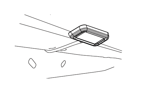
Close and wrap with conduit and electrical tape. Secure all loose wires with cable ties, with lamp wires pulled upward to avoid any wire snagging.
37
Replace power fuse
Check that all doors activate the Power Step and the LED Lights work when doors open and close. Reinstall any remaining trim panels.
FINAL SYSTEM CHECK
Check that all doors activate the PowerStep and the LED lights work when doors open and close. NORMAL OPERATION: When the doors open, PowerStep automatically deploys from under the vehicle. When the doors are closed, PowerStep will automatically return to the stowed/retracted position. Note that there is a 2-second delay before the PowerStep returns to the stowed/retracted position.
CORRECT OPERATION OF LIGHTS: All four lamps will illuminate upon opening any door of vehicle. Lamps will stay on until restowing of both Power Steps or until 5 minutes has expired with the doors open. When the lights timeout after 5 minutes, they can be reillumintated by closing and opening any door of vehicle.
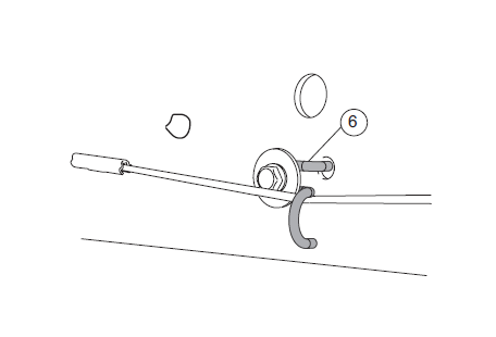
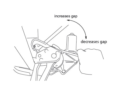
Slight adjustments to the upper mount can be made to adjust stow positon. With the board extended, loosen hex bolt as shown, adjust as needed, and retighten hex bolt to 16 ft-lbs. The adjustments will be made to either increase or decrease the gap between the board and rocker panel when stowed.
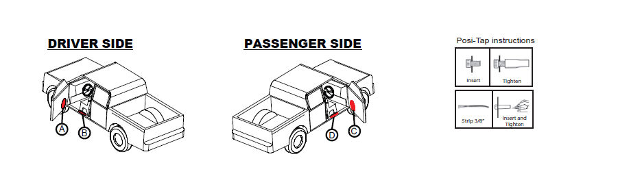
DRIVER SIDE WIRING
1. After removing the front door step plate, lift carpet and pull Powerstep trigger wires through floor of truck.
2. Open wire bundle located under front door step plate and locate the 18Ga. rear door-ajar signal wire (light blue with a black stripe).
3. Apply Posi-Tap connector to the above found wire.
4. Strip wire back approx 3/8” and attach to Posi-Tap connector.
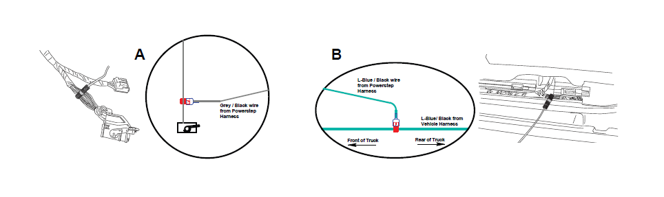
5. After removing the door panel, you will access the wire bundle at the black cam-plug from window control panel (Area-A). Undo wire wrap and locate the 18Ga. door-ajar signal wire (grey with a black stripe).
6. Apply Posi-Tap connector to the above found wire.
7. The longer of the two wires from step-1 will be routed to the door panel through front door accordian. Attach routed wire from Powerstep harness to Posi-Tap connector.
PASSENGER SIDE WIRING
1. After removing the front door step plate, lift carpet and pull Powerstep trigger wires through floor of truck.
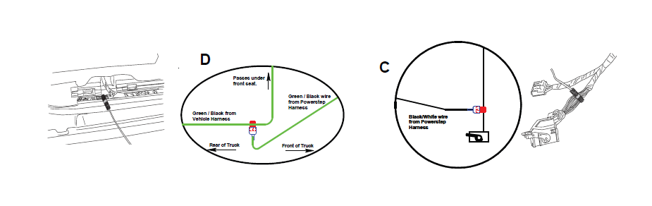
2. Open wire bundle located under front door step plate and locate the 18Ga. rear door-ajar signal wire (green with a black stripe).
3. Apply Posi-Tap connector to the above found wire.
4. Strip wire back approx 3/8” and attach to Posi-Tap connector.
5. After removing the door panel, you will access the wire bundle at the black cam-plug from window control panel (Area -C). Undo wire wrap and locate the 18Ga. door-ajar signal wire (black with a white stripe).
6. Apply Posi-Tap connector to the above found wire.
7. The longer of the two wires from step-1 will be routed to the door panel through front door accordian. Attach routed wire from Powerstep harness to Posi-Tap connector.
Notes:
1. All of the signal wires tapped into will be 18Ga. Do not tap into anything with a thicker gage than this.
2. Occassionally the wire colors do not match the wire schematics. Under these circumstances you will need to locate the door-ajar signal wires.
3. Make sure to secure all wires after install. Loose wires can be damaged and may cause a failure in the Powerstep's function.
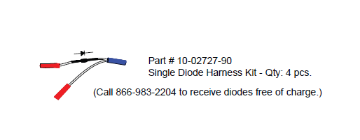
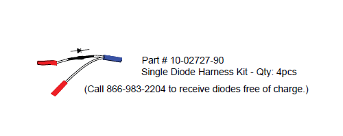
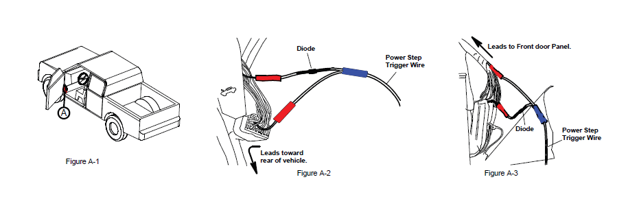
ATTENTION: Pay close attention to the orientation of the diode harnesses. The Power-Step will not work with a incorrectly installed diode harness.

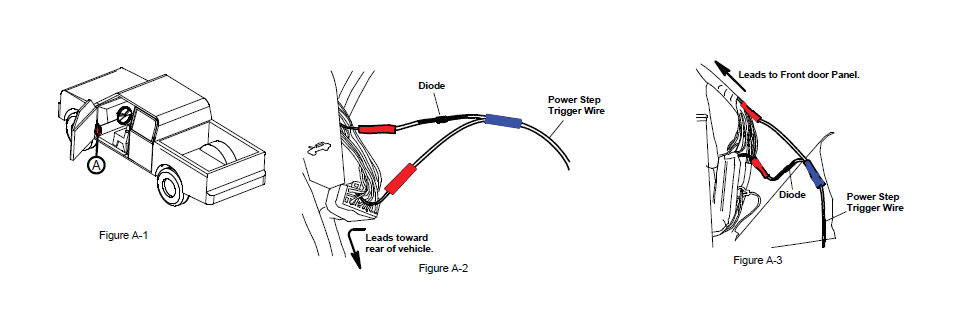
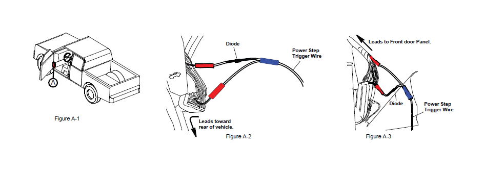
DRIVER SIDE WIRING
1. After removing the front door step plate and kick plate, lift carpet and pull Powerstep trigger wires through floor of truck.
2. Locate the rear door-ajar signal wire (dark blue with white stripe) on black connector below the hood-release lever (Area-A in Figure A -1). There should be two wires of this color; use the wire located on the row closest to the plug release.
3. Cut this wire and install Single Diode Harness as oriented in Figure A-2.
4. After timming to correct length, connect the light blue with black stripe trigger wire from step one to the blue connector of Single Diode Harness installed in previous step.
5. Locate the front door-ajar signal wire (tan) on large connector located behind the connector of step 2.
6. Cut this wire and install Single Diode Harness as oriented in Figure A-3.
7. After timming to correct length, connect the grey with black stripe trigger wire from step one to the blue connector of Single Diode Harness installed in previous step.
8. Wrap all connections with electrical tape and secure any loose wires.
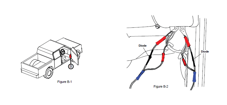
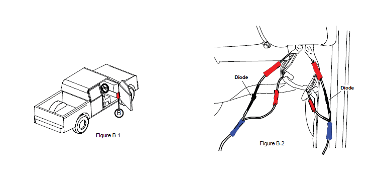
PASSENGER SIDE WIRING
1. After removing the front door step plate, lift carpet and pull Powerstep trigger wires through floor of truck.
2. Locate the two wire bundles running up along kick panel area underneith glove compartment as shown in the above figures.
3. Open wire wrap of the bundles and locate the front and rear doorajar signal wires (dark blue with white stripe), one found in each bundle.
4. Cut each wire and install the Single Diode Harnesses as oriented in Figure B-2. Make certain that the leg with the diode is towards the top.
5. Wrap all connections with electrical tape and secure any loose wires.
Notes:
1. All of the signal wires tapped into will be 18Ga. Do not tap into anything with a thicker gage than this.
2. Occassionally the wire colors do not match the wire schematics. Under these circumstances you will need to locate the door-ajar signal wires.
3. Make sure to secure all wires after install. Loose wires can be damaged and may cause a failure in the Powerstep's function.
ATTENTION: Pay close attention to the orientation of the diode harnesses. The Power-Step will not work with a incorrectly installed diode harness.
DRIVER SIDE WIRING
1. After removing the front door step plate and kick plate, lift carpet and pull Powerstep trigger wires through floor of truck.
2. Locate the rear door-ajar signal wire (orange) on black connector below the hood-release lever (Area-A in Figure A-1). There should be two wires of this color; use the wire located on the row closest to the plug release.
3. Cut this wire and install Single Diode Harness as oriented in Figure A-2.
4. After timming to correct length, connect the light blue with black stripe trigger wire from step one to the blue connector of Single Diode Harness installed in previous step.
5. Locate the front door-ajar signal wire (tan) on large connector located behind the connector of step 2.
6. Cut this wire and install Single Diode Harness as oriented in Figure A-3.
7. After timming to correct length, connect the grey with black stripe trigger wire from step one to the blue connector of Single Diode Harness installed in previous step.
8. Wrap all connections with electrical tape and secure any loose wires.
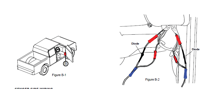
PASSENGER SIDE WIRING
1. After removing the front door step plate, lift carpet and pull Powerstep trigger wires through floor of truck.
2. Locate the two wire bundles running up along kick panel area underneith glove compartment as shown in the above figures.
3. Open wire wrap of the bundles and locate the front and rear doorajar signal wires (dark blue with white stripe), one found in each bundle.
4. Cut each wire and install the Single Diode Harnesses as oriented in Figure B-2. Make certain that the leg with the diode is towards the top.
5. Wrap all connections with electrical tape and secure any loose wires.
Notes:
1. All of the signal wires tapped into will be 18Ga. Do not tap into anything with a thicker gage than this.
2. Occassionally the wire colors do not match the wire schematics. Under these circumstances you will need to locate the door-ajar signal wires.
3. Make sure to secure all wires after install. Loose wires can be damaged and may cause a failure in the Powerstep's function.
ATTENTION: Pay close attention to the orientation of the diode harnesses. The Power-Step will not work with a incorrectly installed diode harness.
DRIVER SIDE WIRING
1. After removing the front door step plate and kick plate, lift carpet and pull Powerstep trigger wires through floor of truck.
2. Locate the rear door-ajar signal wire (dark blue with white stripe) wire on black connector below the hood-release lever (Area-A in Figure A-1). There should be two wires of this color; use the wire located on the row closest to the plug release.
3. Cut this wire and install Single Diode Harness as oriented in Figure A-2.
4. After timming to correct length, connect the light blue with black stripe trigger wire from step one to the blue connector of Single Diode Harness installed in previous step.
5. Locate the front door-ajar signal wire (light green with black stripe) on large connector located behind the connector of step 2.
6. Cut this wire and install Single Diode Harness as oriented in Figure A-3.
7. After timming to correct length, connect the grey with black stripe trigger wire from step one to the blue connector of Single Diode Harness installed in previous step.
8. Wrap all connections with electrical tape and secure any loose wires.
PASSENGER SIDE WIRING
1. After removing the front door step plate, lift carpet and pull Powerstep trigger wires through floor of truck.
2. Locate the two wire bundles running up along kick panel area underneith glove compartment as shown in the above figures.
3. Open wire wrap of the bundles and locate the rear door-ajar signal wire (dark blue with white stripe) in one bundle and the front doorajar signal wire (light green with black stripe) in the other bundle.
4. Cut each wire and install the Single Diode Harnesses as oriented in Figure B-2. Make certain that the leg with the diode is towards the top.
5. Wrap all connections with electrical tape and secure any loose wires.
Best Sellers
-
 J&L 3.0 Oil Separator; Black Anodized; Passenger Side (11-26 2.7L/3.5L EcoBoost F-150)
 (500+)
$152.10 $169.00
(500+)
$152.10 $169.00