FREE 1 to 3-Day Delivery on Orders $149+ Details
How to Install AEM Electronics X-Series Boost Pressure Gauge - Electrical (07-17 Silverado 1500) on your Chevy Silverado
STOP! - READ THIS BEFORE INSTALL OR USE!
WARNING: THIS INSTALLATIONMAY REQUIREWELDING OR INTEGRATION INTO A VEHICLE'S ELECTRICAL SYSTEM. DAMAGE TO SENSITIVEELECTRONICS, FIRE, OR EXPLOSIONMAY OCCUR IF PROPER PRECAUTION IS NOT TAKEN. IF THERE IS ANY DOUBT, DO NOT ATTEMPT THEINSTALLATION AND CONSULT A PROFESSIONAL. NOTE: IT IS THERESPONSIBILITY OF THEENGINETUNER TO ULTIMATELY CONFIRMTHECALIBRATION USEFOR ANY PARTICULAR ENGINEIS SAFEFOR ITS INTENDED USE. AEMHOLDS NO RESPONSIBILITY FOR ANY ENGINE DAMAGETHAT RESULTS FROMTHEMISUSEOF THIS PRODUCT.
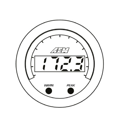
The 52mm (2-1/16”) AEM X-Series Gauge features a four digit central readout and sweeping 24-color-coded LED display, providing immediate reference to the sensor reading in real-time. A 0-5V analog and an AEMnet (CAN bus) output is included and can be used with data loggers or aftermarket ECUs including the AEM Infinity Engine Management System (EMS).
Features
· 2-1/16" / 52mm outer diameter mounting
· Flashing warn / alarm feature
· Peak recall
· US or metric / SI display modes with reversible faceplate
· Black bezel / "Oil" faceplate supplied; Silver / white available as optional purchase
· Locking connectors
· Supports vehicle / system voltages up to 16V
· Auto-dimming display
· 0-5V analog output
· AEMnet (CAN bus) output
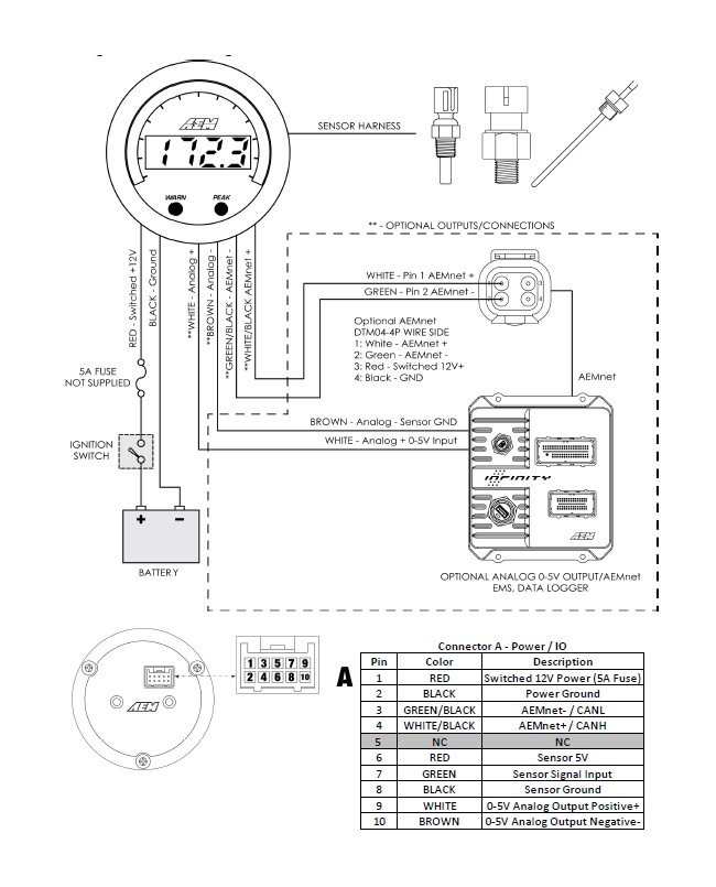
Wiring Installation Diagram
Operation
The inner numeric LEDs and outer ring LEDs display the currently measured sensor reading; the inner numeric LEDs will flash when the sensor reading exceeds the (configurable) warn/alarm threshold value. WARN and PEAK buttons are located on the face of the gauge and are used to perform the following functions.
Change display units US / SI (metric)
> The gauge should be in its normal display mode, showing the current sensor reading
> Depress and hold the WARN button for three seconds until US or SI appears
> Press the WARN button to toggle between US or SI (metric) modes
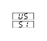
English / US units mode
Metric / SI units mode
Display or adjust warn/alarm threshold
> Press the WARN button; the warn/alarm threshold will be displayed and the outer LEDs will flash
> Use either the WARN or PEAK buttons to decrement or increment the threshold value
> Depress and hold both the WARN and PEAK buttons until LESS or GrTr appears
> Press the WARN button to toggle between LESS and GrTr modes

Warn/alarm activated when sensor reading is less than threshold value
Warn/alarm activated when sensor reading is greater than threshold value
> The gauge will return to normal display mode a few seconds after the last button press
Display or clear stored peak value
> Press the PEAK button; the peak (highest) sensor reading will be displayed and the outer LEDs will flash
> The peak value will be retained across power cycles
> While the peak value is being displayed, depress and hold the PEAK button for three seconds until "CLr" appears to clear the peak value
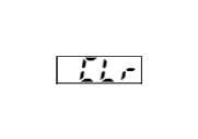
Will be displayed to confirm the peak value has been reset
> The gauge will return to normal display mode shortly after the last button press
Sensor Installation
> Install sensor with a liquid thread sealant suitable for NPT fittings.
> Remote mounting pressure sensors using flexible tubing and anti-vibration mounts will help extend sensor life.
> Secure wiring to vehicle with wire ties paying special attention to the sensor harness routing beneath the vehicle and/ or in the engine compartment.
> Take care when routing the sensor harness near hot exhaust components, use strain reliefs and wire coverings as appropriate.
> Use a 5A inline fuse on the switched 12V power supply line (Pin 1 - Power/IO).
Faceplate / Bezel Installation
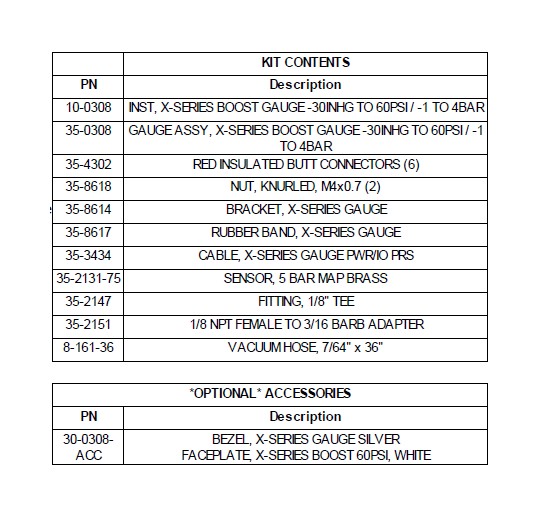
The gauge kit is supplied assembled with a black faceplate and black bezel. An accessory kit is available (for purchase through AEM dealers) which includes an optional silver bezel and white faceplate. Please reference the Optional Accessories section earlier in the document for the appropriate part numbers. Contact your dealer or visit www.aemelectronics.com for more information.
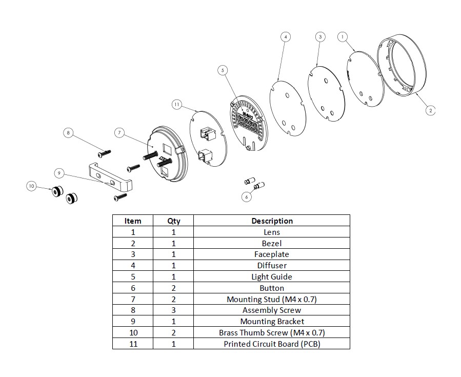
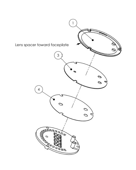
The faceplate may be reversible, displaying alternative scalings on either side. Reference the Operation section of this manual for details on how to switch the display mode when reversing the faceplate. Disassembly is required to change the faceplate, flip/reverse the faceplate, or change the bezel of the gauge. The following diagram will provide familiarization with the major components of the gauge prior to beginning the procedure.
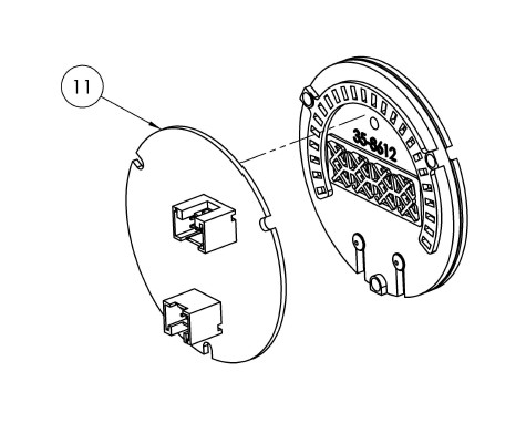
Gauge Disassembly
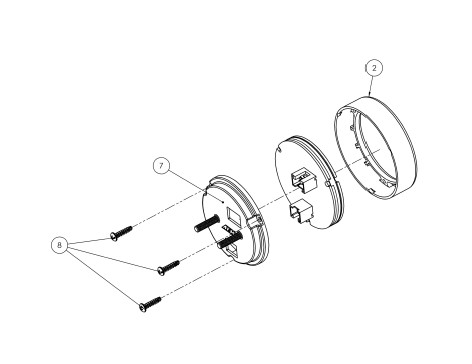
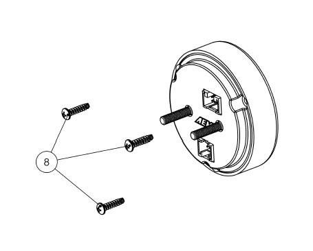
STEP 1 - Remove the three assembly screws (8) using a #1 Phillips head screwdriver. Separate the bezel (2) and cup (7) fromthe rest of the assembly. If you have purchased the optional accessory kit, the silver bezel may be replaced for the existing bezel at this time
STEP 2 - Separate the PCB (11) fromthe remaining components
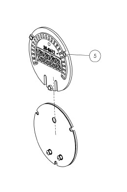
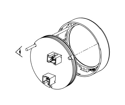
STEP 3 - Slide the light guide (5) upward to remove it, the buttons may fall out at this time - take care not to lose them
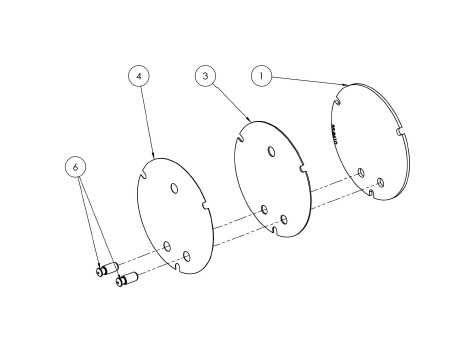
STEP 4 - As you separate the remaining components, diffuser (4), faceplate (3), lens (1), note the order in which they were assembled. The faceplate (3) may now be reversed to display an alternate scaling or replaced for a different color as included in the optional accessory kit
Gauge Assembly
STEP 1 - Place the light guide (5) on a flat surface (black side up) and slide the buttons (6) into the slots
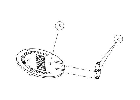
STEP 2 - Stack the diffuser (4), faceplate (3), and lens (1) in order, over the buttons, and on to the light guide
STEP 3 - Reassemble the PCB and display stack with the bezel, making sure screw holes are aligned through the entire assembly
STEP 4 - Reassemble and tighten screws to 2 in-lb (previously assembled bezel) or 3 in-lb (new bezel). Do not over-tighten!
Gauge Installation
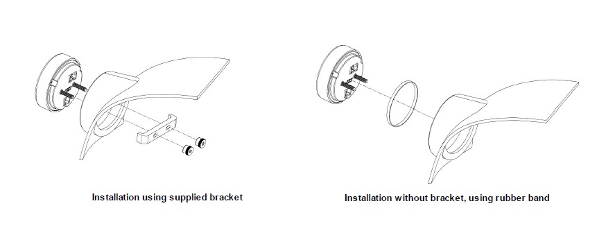
A 2-1/6" (52mm) hole is required to mount the X-Series gauge. A bracket and thumbscrews are provided to facilitate installation into a panel or gauge pod. In some cases, the gauge cup may be pushed into a mounting hole causing an interference fit strong enough to retain the gauge; the supplied rubber band may be fit to the gauge to create a tighter fit in mounting holes slightly larger than 52mm. It is, however, recommended that gauges be mounted securely using the supplied bracket to ensure they never become loose and cause a hazard during vehicle operation.
Note: The gauge is not water-proof and should not be installed in a location with exposure to water or snow. Damage caused by water ingress will not be covered under warranty.
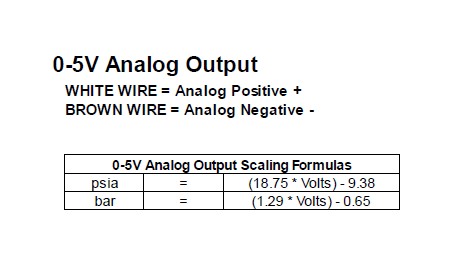
The 0-5V analog output is suitable for output to devices such as loggers or ECUs. This differential output requires special care to ensure proper operation. The WHITE signal wire should be connected to the positive of the analog input of the logging device or ECU; the BROWN wire must be connected to the negative of the analog input of the logging device or ECU. If the logging device or ECU does not have a differential analog input (both a dedicated positive and negative terminal for the analog input) then connect the BROWN wire to the shared signal ground. If the device does not have a dedicated signal ground then as a last course of action, connect it to the power ground of the logging device.
Important Note: If bench testing the analog output outside of a vehicle, a multimeter's positive lead may be connected to the WHITE wire however the BROWN wire must be connected to BOTH the multimeter's negative lead AND power ground going to the X-Series device. This connection is usually made by the circuitry inside an ECU or data logger.
AEMnet (CAN bus) Output
WHITE WIRE WITH BLACK STRIPE = AEMnet / CANH
GREEN WIRE WITH BLACK STRIPE = AEMnet- / CANL
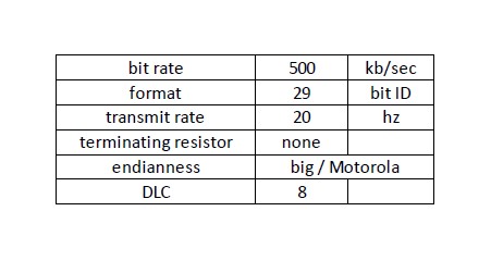
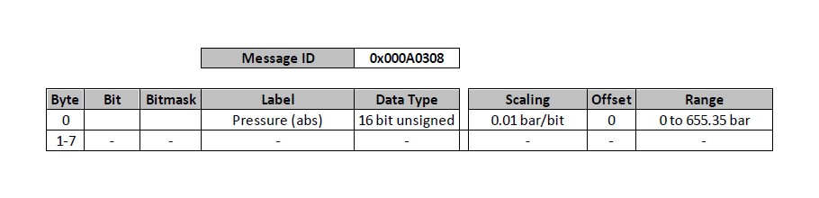
The AEMnet output is suitable for output to AEM devices such as the AQ-1 data logger or Infinity ECU. The following CAN configuration and message definition information is provided below to facilitate interface with third-party devices.
Bus Termination
All AEMnet/CAN networks must be terminated to have an equivalent of approximately 60 Ohms of resistance. Generally, this means a 120 Ohm resistor connected in parallel to AEMnet /AEMnet- (or CANH/CANL) at both physical ends of the bus run. The X-Series device does not have any internal termination and is intended to be connected to a pre-existing, properly terminated network. Please refer to the Bosch CAN2.0B specification for further detail.
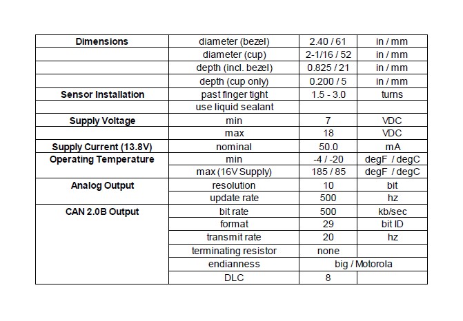
Specifications