 FREE 1 to 3-Day Delivery on Orders $149+ Details
How To Install a Zone Offroad 4 inch Suspension Lift Kit On Your 2015-2016 Ford F-150 4WD
Shop Parts in this Guide
Read and understand all instructions and warnings prior to installation of product and operation of vehicle.
Zone Offroad Products recommends this system be installed by a professional technician. In addition to these instructions, professional knowledge of disassembly/ reassembly procedures and post installation checks must be known. Minimum tool requirements include the following: Assorted metric and standard wrenches, hammer, hydraulic floor jack and a set of jack stands. See the "Special Tools Required" section for additional tools needed to complete this installation properly and safely.
Product Safety Warning
Certain Zone Suspension Products are intended to improve off-road performance. Modifying your vehicle for off-road use may result in the vehicle handling differently than a factory equipped vehicle. Extreme care must be used to prevent loss of control or vehicle rollover. Failure to drive your modified vehicle safely may result in serious injury or death. Zone Offroad Products does not recommend the combined use of suspension lifts, body lifts, or other lifting devices. You should never operate your modified vehicle under the influence of alcohol or drugs. Always drive your modified vehicle at reduced speeds to ensure your ability to control your vehicle under all driving conditions. Always wear your seat belt.
Technical Support
Live Chat provides instant communication with Zone tech support. Anyone can access live chat through a link on www.zoneoffroad.com .
www.zoneoffroad.com may have additional information about this product including the latest instructions, videos, photos, etc.
Send an e-mail to [email protected] detailing your issue for a quick response.
888.998.ZONE Call to speak directly with Zone tech support.
Pre-Installation Notes
1. Special literature required: OE Service Manual for model/year of vehicle. Refer to manual for proper disassembly/reassembly procedures of OE and related components.
2. Adhere to recommendations when replacement fasteners, retainers and keepers are called out in the OE manual.
3. Larger rim and tire combinations may increase leverage on suspension, steering, and related components. When selecting combinations larger than OE, consider the additional stress you could be inducing on the OE and related components.
4. Post suspension system vehicles may experience drive line vibrations. Angles may require tuning, slider on shaft may require replacement, shafts may need to be lengthened or trued, and U-joints may need to be replaced.
5. Secure and properly block vehicle prior to installation of Zone Offroad Products. Always wear safety glasses when using power tools.
6. If installation is to be performed without a hoist, Zone Offroad Products recommends rear alterations first.
7. Due to payload options and initial ride height variances, the amount of lift is a base figure. Final ride height dimensions may vary in accordance to original vehicle attitude. Always measure the attitude prior to beginning installation.
Tire/Wheel Fitment
6" Lift:
37x12.50 on 18x9 5" backspacing*
37x12.50 on 20x9 5.5" backspacing
4" Lift: 35x12.50 on 18x9 5" backspacing*
35x12.50 on 20x9 5.5" backspacing
*See Pre-Installation Notes
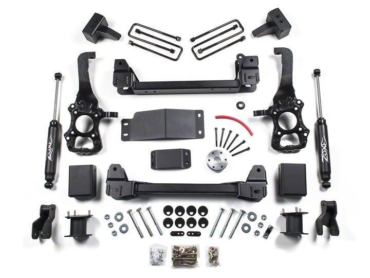
*Important* Verify you have all of the kit components before beginning installation.
F2640- Knuckle Box - Drv
| Qty | Description |
|---|---|
| 1 | Knuckle - Drv |
| 1 | Ball Joint Washer |
F2641 Knuckle Box - Pass
| Qty | Description |
|---|---|
| 1 | Knuckle - Pass |
| 1 | Ball Joint Washer |
F2634 Front Box Kit
| Qty | Description |
|---|---|
| 1 | Front Crossmember |
| 2 | Differential Drop Bracket |
| 1 | Pass Side Differential Bracket |
| 1 | Differential Skid |
| 1 | Driveshaft Spacer |
F2635 Front Box Kit
| Qty | Description |
|---|---|
| 1 | Rear Crossmember |
| 2 | Sway Bar Drop |
| 8 | Cam Washer |
| 4 | Eccentric Bolt |
| 2 | M18-2.5 x 150mm Bolt |
| 6 | M18-2.5 prevailing torque nut |
| 4 | 3/4" USS washer |
| 2 | Front Brake Line Bracket |
| 1 | Differential Vent Hose |
| 1 | Loctite |
| 1 | Bolt Pack 925 - Driveshaft Spacer |
| 6 | 10mm-1.50 x 100mm socket head bolt |
| 1 | Bolt Pack 781 - Differential Drop/Misc |
| 2 | 9/16"-12 x 4" bolt |
| 1 | 9/16"-12 x 3-3/4" bolt |
| 1 | 9/16"-12 x 1-1/4" bolt |
| 8 | 9/16" SAE washer |
| 4 | 9/16"-12 Prevailing torque nut |
| 2 | 1/2"-13 x 3" bolt |
| 4 | 1/2"-13 x 1-1/4" bolt |
| 8 | 1/2" SAE washer |
| 2 | 1/2"-13 Prevailing torque nut |
| 4 | 3/8"-16 x 1-1/4" bolt |
| 8 | 3/8" SAE Washer |
| 4 | 3/8"-16 Prevailing torque nut |
| 2 | 1/4"-20 prevailing torque nut |
| 4 | 1/4" SAE flat washer |
| 2 | 6mm-1.00 x 18mm bolt |
| 1 | Bolt Pack 407 - Sway Bar |
| 8 | 3/8" USS washer |
| 4 | 7/16"-14 x 1-1/4" bolt |
| 4 | 7/16"-14 prevailing torque nut |
F2404 /F2604 Strut Spacer Box Kit
| Qty | Description |
|---|---|
| 2 | Strut Spacer |
| 1 | Bolt Pack - 769 - Strut Spacer |
| 6 | 7/16"-14 nylock nut clear zinc |
| 6 | 3/8" USS flat washer clear zinc |
| 1 | Bolt Pack 629 - Strut Spacer |
| 6 | 10mm-1.50 prevailing torque nut |
| 6 | 3/8" USS flat washer |
F2419 Rear Box Kit (6" only)
| Qty | Description |
|---|---|
| 2 | 5in Rear Block |
| 1 | E-Brake Bracket (2009-14 only) |
| 2 | Lower Spring Plate |
| 2 | Upper Spring Plate |
| 1 | Brake Line Bracket |
| 2 | 1/2" x 4" Center Pin & Nut |
| 4 | 9/16 x 3-1/8 x 12-1/2 Square U-bolt |
| 8 | 9/16" SAE washer |
| 8 | 9/16" High Nut |
| 1 | Bolt Pack 768 |
| 2 | 1/4"-20 x 3/4" bolt |
| 2 | 1/4"-20 nylock nut |
| 4 | 1/4" USS flat washer |
| 1 | Bolt Pack 774 |
| 2 | 1/2"-20 x 3-1/2" Flat Socket Head Bolt |
| 2 | 1/2"-20 non-locking nut |
| 2 | 7/16"-14 x 1-1/4" bolt |
| 4 | 7/16" SAE washer |
| 2 | 7/16"-14 prevailing torque nut |
| 1 | 1/4"-20 prevailing torque nut |
| 1 | 1/4" USS washer |
F2418 Rear Box Kit (4" only)
| Qty | Description |
|---|---|
| 1 | 4in rear block - Drv |
| 1 | 4in rear block - Pass |
| 1 | 9/16 x 3-1/8 x 12-1/2 Square U-bolt |
| 8 | 9/16 SAE washer |
| 8 | 9/16" fine high nut |
| 1 | brake line bracket |
| 1 | Bolt Pack 704 - brake line bracket |
| 2 | 1/4"-20 prevailing torque nut |
| 2 | 1/4" SAE flat washer |
Installation Instructions
Pre-Installation Notes
1. 18" or larger diameter wheels required. Stock 17" and 18" wheels cannot be reinstalled. Stock 20’ wheels can be used with up to a 305/60R20 tire.
2. 18" wheels with 5-5.5" backspacing should be test fit prior to mounting the tire to ensure proper clearance to the steering knuckle/tie rod. 18 - 20"wheels with 5.5" of backspacing is highly recommended for tire to frame crash bar clearance. 37" tires will require crash bar modification
3. Models with 2-piece rear driveshaft WILL require carrier bearing shim kit D5405 (not included w/ kit).
Important—measure before starting!
Measure from the center of the wheel up to the bottom edge of the wheel opening.
LF__________ RF__________
LR__________ RR__________
Caution:
EPAS (Electronic Power Assist Steering), disconnect the power steering control module connector to avoid arching of the contacts in the internal power relay from a hammer blow or impact wrench.
Front Installation
1. Park the vehicle on a clean, flat surface, and block the rear wheels for safety.
2. Raise the front of the vehicle and support with jack stands at each frame rail behind the lower control arms.
3. Remove the front wheels.
4. If equipped, remove the transmission shield (Ecoboost models) and front splash shield by unclipping it from the air dam and removing the mounting bolts.
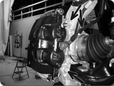
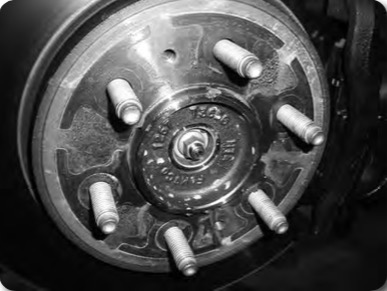
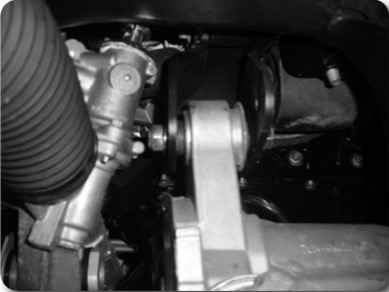
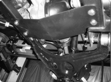
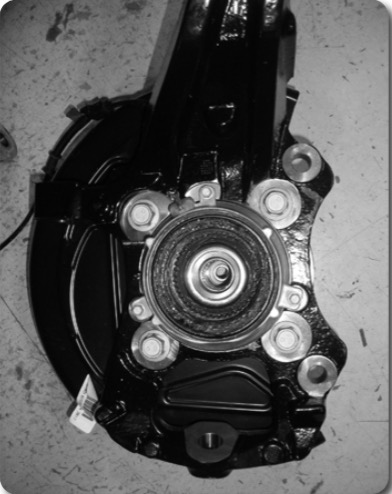
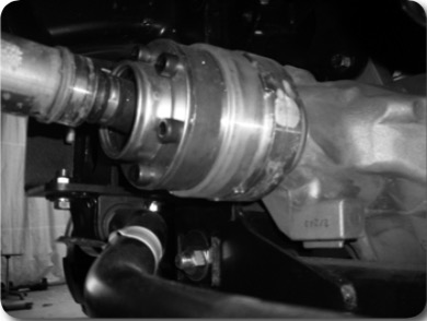
5. Remove the brake caliper anchor bracket bolts and remove the caliper from the knuckle (Figure 1). Hang the caliper out of the way. Do not let the caliper hang by the brake hoses.
6. Disconnect the hub vacuum line from the hub (Figure 1).
Figure 1
7. Remove the brake rotor and set aside.
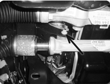
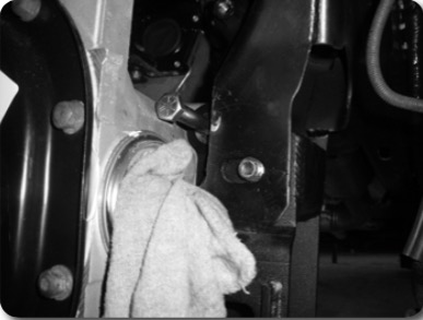
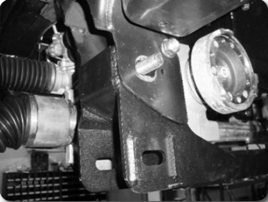
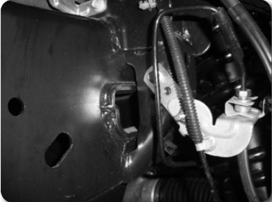
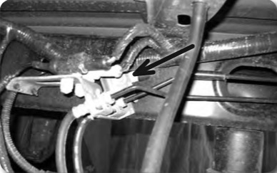
8. Disconnect the ABS and hub vacuum lines from the retaining clips. Disconnect the brakeline bracket from the frame rail. Disconnect the ABS line from the hub assembly. (Figure 2 & 3).
Figure 2
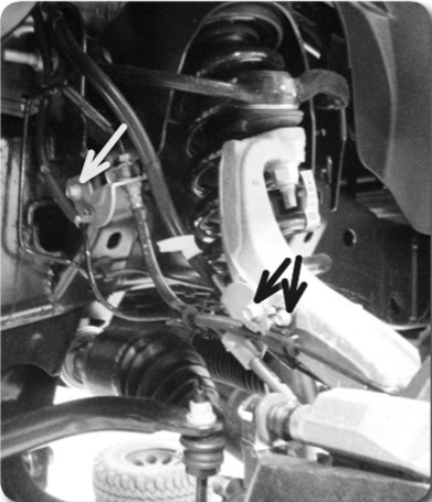
Figure 3
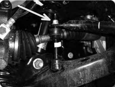
9. Disconnect the tie rod ends from the steering knuckles. Remove and retain the mounting nuts. Avoid hitting the aluminum steering knuckle, use appropriate tool to remove tie rod end from steering knuckle. Take care not to strike the tie rod end, or damage the threads. (Figure 4)
Figure 4
10. Disconnect the sway bar links from the sway bar (Figure 5A). Retain hardware. The sway bar links do not need to be removed from the lower control arms.
Figure 5A
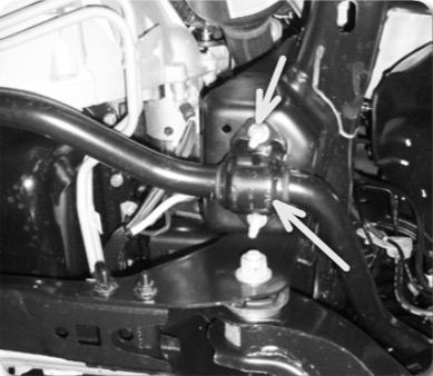
11. Remove the four sway bar mounting nuts and remove the sway bar from the vehicle. (Figure 5B) Retain hardware
Figure 5B
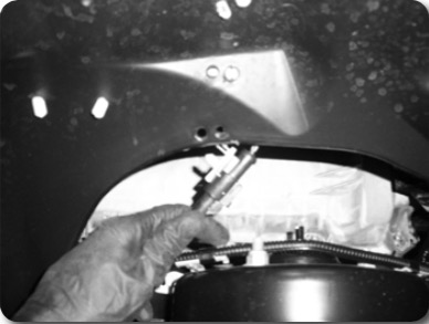
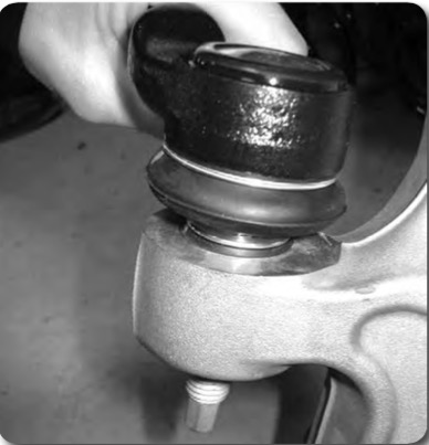
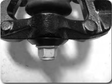
12. Carefully remove the hub dust cap to expose the axle shaft nut. (Figure 6A, 6B). Remove the nut. Retain the cap and nut, they will be reinstalled later.
Figure 6A
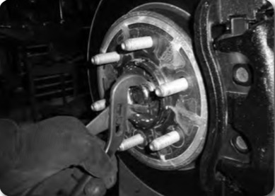
Figure 6B
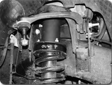
13. Loosen but do not remove the three strut assembly mounting nuts at the frame (Figure 7). Do not loosen the middle strut nut.
Figure 7
14. Remove the upper and lower ball joint nuts, refrain from hitting the aluminum steering knuckle, use appropriate tool to separate ball joints, avoid damaging the threads.
15. Remove the upper ball joint and the strut-to-lower control arm hardware. Swing the knuckle/lower control arm down to remove the CV shaft from the hub. Retain ball joint nut and strut bolt.
16. Remove the lower ball joint nut and remove the knuckle from the vehicle. Retain hardware.
17. Remove the lower control arm mounting bolts and remove the lower control arm from the vehicle. Retain hardware. 18. Mark the struts to distinguish between driver’s and passenger’s.
19. Remove the three strut assembly mounting nuts at the frame and remove the strut assembly from the vehicle.
20. Remove the four bolts that attach the OE rear crossmember to the frame. Discard the crossmember and hardware.
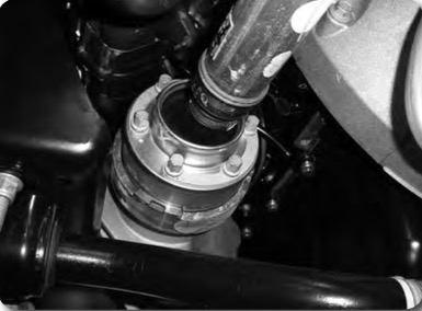
21. Remove the driveshaft mounting bolts and disconnect the driveshaft from the differential (Figure 8). Allow the driveshaft to rest out of the way.
Figure 8
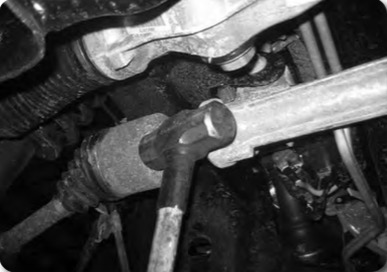
22. Remove the passenger's side CV shaft. Strike the shaft with a hammer to dislodge it from the splines. This will make handling the differential much easier. (Figure 9)
Figure 9
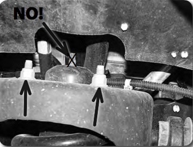
23. Support the front differential with an appropriate jack. Loosen all of the hardware and slide the differential all the way to the passenger's side. Orientate the joint at the steering rack so there is the most possible clearance to remove the front driver's side bolt. Remove this bolt first. Disconnect the differential breather hose from the differential housing. Remove the rear driver’s side and one passenger’s side differential mounting bolts (Figure 10 / 11 / 12) and remove the differential from the vehicle.
Figure 10
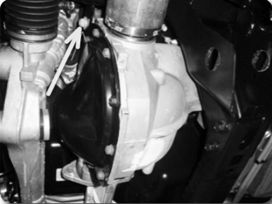
Figure 11
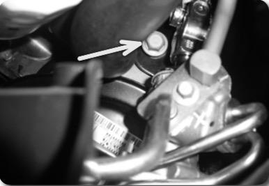
Figure 12
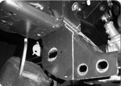
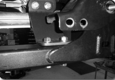
24. The driver’s side rear lower control arm frame pocket must be modified to provide clearance for the differential in its relocated position. On the front side measure from the inside edge of the factory control arm slot 5/8" (Figure 13). Make a vertical cut line at the mark.
Figure 13 Note:
Measure in 5/8" from inside of slot edge.
Figure 13
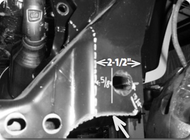
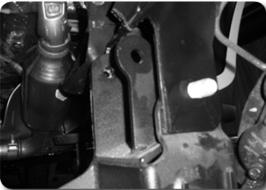
25. On the back side measure from the outside edge of the control arm slot 4-1/2" and mark (Figure 14). Make a vertical cut line at the mark.
Figure 14
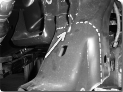
26. On the 'inside' face, measure up 3/4" from the bottom of the original differential mount bracket. Draw a horizontal line to the front and rear face. (Figure 15)
27. Trim the area from the vehicle.
Step 27 Note:
Measure up 3/4" from the edge as shown.
Figure 15
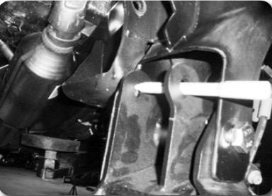
28. Install the rear crossmember (Figure 17)
Figure 17
29. With the crossmember installed mark the differential hole on the factory control arm bracket. Remove the crossmember and drill a 5/8" hole at the mark, for easiest access drill the hole from front to back. (Figure 18)
Figure 18
30. Install the passenger side and front driver side differential brackets onto the differential, run the provided 9/16" hardware from front to rear for clearance to the steering rack.
Step 30 Note:
Drill hole from front to rear.
31. Loosely install the new differential drop brackets in the passenger’s side and front driver’s side factory differential mounting locations with the factory hardware. The brackets should offset toward the front of the vehicle when properly installed
Step 31 Note:
Differential bracket hardware is located in bolt pack 781 The driver's side front bolt is 9/16" x 3-3/4"
32. Raise the differential in the vehicle by aligning the OE differential mounts to the two front drop brackets. Attach the brackets to the frame with the OE hardware. (Figure 19)
Figure 19
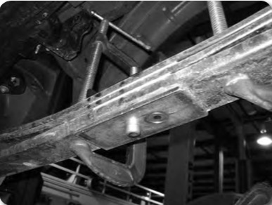
33. Install the new rear crossmember in the rear lower control arm frame pockets and fasten with new 18mm bolts and washers (do not put nuts on at this time). Run bolts from front to rear. Leave hardware loose. Ensure the hole that was drilled in the frame pocket lines up to the differential mounting hole in the bracket. (Figure 20)
Figure 20 Note:
Run driver's side front diff bolt from front to rear. The driver's side rear bolt is 9/16" x4". (BP #781)
Figure 20
34. Fasten the differential to the rear crossmember (Figure 21) with a 9/16" bolt, washers, and nut. Run the bolt from front to rear. Leave hardware loose.
Figure 21
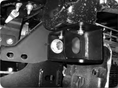
35. Install the offset differential support bracket to the passenger’s side differential bracket using 9/16" hardware and 1/2" x 3" hardware to the crossmember. The horizontal slots will be located up at the differential. Leave hardware loose. (Figure 22)
Figure 22 Note:
Passenger's side differential drop bracket hardware is located in BP #781.
Figure 22
36. Go back and torque all the differential mounting hardware (9/16" and 14mm) to 95 ft-lbs (6 bolts total). Remove the elbow from the vent line and attach the differential hose extension to the line and to the differential.
37. Install the front crossmember in the front lower control arm pockets and fasten with the OE lower control arm hardware. Leave hardware loose.
38. Install the lower control arms in the new crossmembers and fasten with the provided 18mm cam bolts, cam washers and 18mm nuts. Run the front bolts from front to rear and leave loose. Run the rear bolts from rear to front. The main body of the cam will be 'up' in the cam slot
39. Install the provided differential skid plate to the front and rear crossmembers with ½” x 1-1/4” bolts and ½” SAE washers into the threaded holes in the crossmembers (Figure 23). Leave hardware loose.
Figure 23 Note:
1/2" x 1-1/4" bolts with washers - use loctite on threads. (BP #781)
Figure 23
40. Attach the sway bar drop brackets with new 3/8’ x 1-1/4’ bolts, washers and nuts. Run hardware from bottom - up, snug but do not tighten at this time.
Figure 24A
41. With the lower control arms installed torque the four crossmember mounting bolts to 220 ft-lbs. Ensure that the front crossmember is centered in the vehicle. Torque the differential skid plate bolts to 65 ft-lbs. Tighten sway bar drop hardware to 35 ft-lbs.
Step 41 Note:
3/8" x 1-1/4" hardware is located in bolt pack 781.
Use a ratchet extension through the lower slots to access the hardware.
42. Reinstall the passengers side CV.
43. The same strut spacer is used on both sides. Place the strut spacer on each strut and attach with the factory hardware. Tighten to 40 ft-lbs.
44. Install the strut and spacer assembly into the vehicle. Attach to upper mount with new 7/16’ nuts and washers. Leave hardware loose at this time. (Figure 24B)
Figure 24B
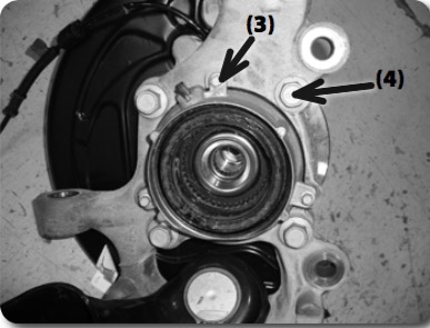
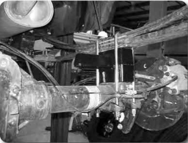
45. Remove the four hub bolts from the knuckle and remove the hub from the knuckle (Figure 25). Inspect mounting surface of the hub assembly and clean any dirt or corrosion off as necessary.
Figure 25
46. Install the hub into the corresponding Zone steering knuckle and fasten with the OE bolts. The ABS wire will be located at the ‘top’ of the hub. Use Loctite on the bolt threads and torque to 148 ft-lbs.
47. Remove the three 6mm bolts mounting the vacuum hub assembly to the inside of the OE knuckle (Figure 26A). Transfer the vacuum assembly over to the new knuckle. Make sure the vacuum port is pointing towards the top. Attach with the OE bolts, tighten bolts securely (about 5-7 ft-lbs).
48. Install the dust shield with the factory 6mm bolts, tighten bolts securely (about 5-7 ft-lbs).
Figure 26A
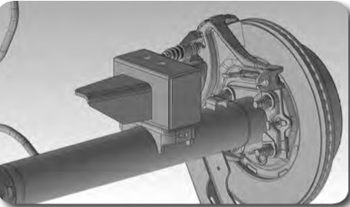
49. Install the new knuckle assembly on the lower control arm ball joint and loosely fasten with the original nut, use the included large machined washer, center on the lower ball joint boss before tightening. Install the CV shaft in the hub, swing the whole assembly up and attach the lower control arm to the strut with the original hardware. Leave all hardware loose. (Figure 26B)
Figure 26B
50. Attach the upper control arm to the knuckle with the original nut. Torque the upper ball joint to 85 ft-lbs and the lower ball joint to 111 ft-lbs.
51. Torque the upper strut nuts to 35 ft-lbs. The lower bolt will be tightened later with the weight of the vehicle on the suspension.
52. Fasten the CV shaft to the hub with the original nut. Make sure the splines are engaged properly in the vacuum actuated section of the hub. The hub should have a very minor amount of rotational play with the CV shaft if installed properly, torque to 20 ft-lbs. Reinstall the dust cap.
53. Install tie rod from top-down. Torque to 111 ft-lbs.
54. Install the brake rotor and caliper to the knuckle with OE bolts. Torque to 148 ft-lbs.
55. Install the brake line relocation brackets at the frame. Attach with factory hardware to frame, attach brakeline retaining clip with 1/4" nut and washer to the relocation bracket. Tighten to 15 ft-lbs. (Figure 27)
Figure 27
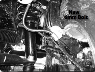
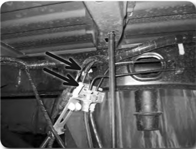
56. Attach the ABS line to the connector at the inner fender and the vacuum line to the hub. Route the lines similar to the factory setup down to the side of the knuckle. Attach the ABS wire with the factory 6mm bolt to the side of the knuckle. Attach the brakeline with a new 6mm x 18mm bolt with 1/4" washer to the side of the knuckle, the brakeline locating tab will go into the un-threaded hole. (Figure 28)
Figure 28
57. Install the sway bar to the new sway bar drop brackets with 7/16” x 1-1/4” hardware. Attach the sway bar to the sway bar end links with the original hardware. Torque the 7/16” hardware to 45 ft-lbs. Torque sway bar link nut to 45 ft-lbs.
Step 57 Note: 1/4" nut and washer is located in bolt pack 781.
58. Install the supplied driveshaft spacer and reattach front driveshaft to differential with new hardware. Torque bolts to 76 ft-lbs. (Figure 29)
Step 58 Note: New 6mm bolt and washer (BP #781) is used to attach the metal brakeline bracket to the steering knuckle.
Figure 29
59. Install the wheels and lower the vehicle to the ground.
Step 59 Note: Sway bar mounting hardware is in BP #407
60. Bounce the front of the vehicle to settle the suspension. Torque the lower strut mount bolts to 80 ft-lbs. Center the lower control arm cams and torque to 150 ft-lbs. Tighten upper strut mounting hardware to 40 ft-lbs. Adjust the toe before driving it to an alignment shop. 61. Cycle steering, the crash bars that protrude from the frame may create clearance issues with the front tires. Modifications may be required for clearance. 62. Check all hardware for proper torque.
Figure 36 Note: 10mm allen head bolts located in bolt pack 925 - use loc-tite on threads
Rear Installation
1. Block the front wheels and raise the rear of the vehicle. Place jack stands under the frame rails ahead of the spring hangers.
2. Remove the wheels.
3. Disconnect the rear brake line from the frame. (Figure 1)
Figure 1
4. 2015 models do not require relocation of the parking brake cable, use care when installing the blocks to ensure adequate slack. Temporarily disconnect the bracket from the frame at the drivers side front spring hanger.
5. Support the rear axle with a hydraulic jack. Remove the factory shocks. Retain mounting hardware.
Note: Perform the rear installation on one side at a time.
6. Remove the passenger’s side u-bolts.
7. Lower the axle and remove the factory lift block, it will not be reused
5" Rear Block Installation
For 4" block installation follow skip to steps 15-16
8. Using C-clamps, clamp the leaf spring pack together on each side of the center pins. Remove the center pins and discard.
9. Place the plate on the bottom of the leaf pack and secure with new center pin in the 'forward' hole and flat head allen bolt through the 'rear' hole. Install new u-bolt retaining plate on top, it will be offset 'forward'. Tighten to 35 ft-lbs. (Figures 2, 3, 4)
Figure 2 Note: Flat head allen bolt is located in BP #774.
Figure 3 Note: Trim excess from centerpin and flat head allen bolt.
Figure 2
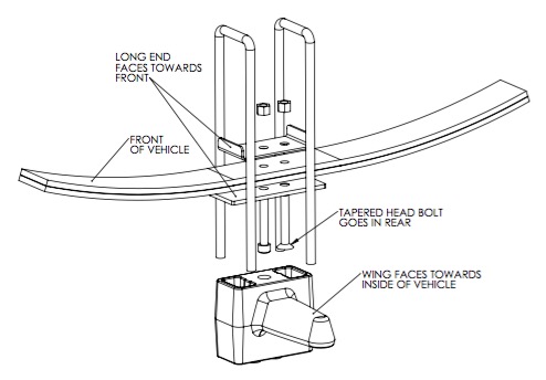
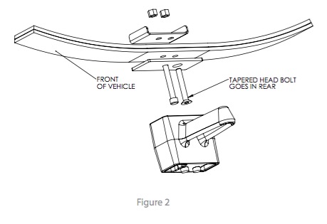
Figure 3
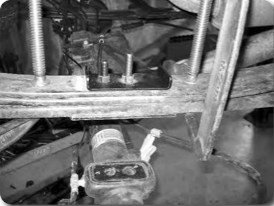
Figure 4
10. Install the new provided lift block so that the bump stop wing goes toward the inside of the vehicle. The block will use the both of the lower center pin holes. The upper only uses 1 hole which will shift the axle slightly forward.
11. Raise the axle/block to the spring while aligning the center pin. Fasten the spring/block assembly with the provided u-bolts, high nuts and washers. Snug u-bolts, they will be torque with the weight of the vehicle on the springs. (Figure 8)
Figure 8
12. Raise the axle and align the center pins. Fasten the assembly with new u-bolts, high nuts, and washers. Snug u-bolts, do not tighten at this time. They will be tightened with the weight of the vehicle on the springs.
13. Repeat installation procedure on the driver’s side of the vehicle.
14. Continue to step 17.
4" Rear Block Installation
15. The fabricated rear blocks are designed to offset the axle forward slightly. The bump stop wing will be centered under the bump stop on the frame. Install the block as shown in the figure, align the center pins and raise axle. (Figure 9)
Figure 9
16. Attach u-bolts with the factory lower u-bolt plate. Snug u-bolts, they will be torqued to specification when the vehicle is on the ground.
Rear Installation - All lifts
17. Install the provided brake line relocation bracket to the driver’s side frame rail with the factory brake line bracket bolt Figure 10. Torque to 15 ft-lbs.
Figure 10
18. Attach the brake line to the relocation bracket with a ¼” nut and ¼” USS washer. It may be necessary to rotate the OE brakeline clip bracket to have the lines face 'down' for adequate slack. Torque to 15 ft-lbs.
19. Install the new shocks with the OE hardware. Torque to 60 ft-lbs.
20. Check all lines/wires for proper slack.
Step 20 Note: Hardware for brake line relocation bracket is located in bolt pack 774 (6" Lifts) or 704 (4" Lifts)
21. Reconnect the power steering control module connector.
22. Install the wheels and lower the vehicle to the ground.
23. Bounce the rear of the vehicle to settle the suspension.
24. Torque the u-bolts to 100-120 ft-lbs.
25. Check all hardware for proper torque
26. Check hardware after 500 miles.
27. A complete front end alignment is necessary.
28. Adjust headlights.
Post-Installation Warnings
1. Check all fasteners for proper torque. Check to ensure for adequate clearance between all rotating, mobile, fixed, and heated members. Verify clearance between exhaust and brake lines, fuel lines, fuel tank, floor boards and wiring harness. Check steering gear for clearance. Test and inspect brake system.
2. Perform steering sweep to ensure front brake hoses have adequate slack and do not contact any rotating, mobile or heated members. Inspect rear brake hoses at full extension for adequate slack. Failure to perform hose check/ replacement may result in component failure.
3. Perform head light check and adjustment.
4. Re-torque all fasteners after 500 miles. Always inspect fasteners and components during routine servicing.

