FREE 1 to 3-Day Delivery on Orders $149+ Details
How to Install SuperLift 3.5 in. Upper Control Arm Leveling Kit w/ Superide Shocks on your Silverado

Shop Parts in this Guide
FRONT DISASSEMBLY
NOTE: Save all factory components and hardware for reuse, unless noted.
1) PREPARE VEHICLE...
Place vehicle in neutral. Raise front of vehicle with a jack and secure a jack stand beneath each frame rail, behind the lower control arms. Ease the frame down onto the stands, place transmission in low gear or “park”, and chock rear tires. Remove front tires.
Disconnect the battery.
Remove front splash guard and skid plates.
2) LOWER CONTROL ARM BOLTS...
Loosen the two control arm bolts.
3) TIE ROD ENDS…
Remove the nuts securing the tie rod ends to the knuckle. Using the appropriate puller tool, separate the tie rod end from the knuckle.
4) ANTI-SWAY BAR LINKS…
Measure and record the amount of exposed threads above the nut on the anti-sway bar link. On each side, loosen and remove the bushings and hardware attaching the anti-sway bar link to bar body and the lower control arm.
5) STRUT REMOVAL…
Support the lower control arm with a jack.
Mark the location of each strut (driver and passenger side) as well as the outermost stud of each strut for later reference during re-assembly.
Remove the two bolts securing the strut to the lower control arm, followed by the three nuts securing the strut to the frame. Remove the strut while taking precautions not to damage any other vehicle components.
6) CONTROL ARM...
Mark the position of the alignment cam bolt washers on the frame.
Disconnect the brake line bracket from the upper control arm.
With the control arm still supported with a jack. Remove the upper ball joint nut and, using the appropriate puller tool, separate the upper control arm ball joint from the knuckle. NOTE: Support the steering knuckle so the inner CV joint does not dislodge from the socket.
Remove the upper control bolts and remove the upper control arm from the vehicle.
FRONT ASSEMBLY
7) CONTROL ARM...
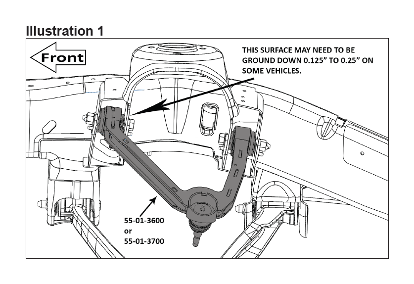
[Illustration 1] Install the new upper control arm in the frame using the factory hardware. Do not tighten at this time.
8) STRUT SPACERS...
WARNING: Extreme care must be taken during the following steps. The struts have a tremendous amount of energy stored in them and can cause serious injury or even death if an attempt is made to work on them without the proper tools. Dis-assembly / assembly of the struts can only be performed by a qualified professional with the special equipment designed for this task. If necessary, the struts can be taken to a shop with the proper equipment to have the necessary work performed.
NOTE: A factory service manual should be on hand for reference. Perform the strut assembly and installation one side at a time.
Place the strut assembly in a heavy-duty strut compressor and compress the coil spring enough to unload the shock.
Rotate the shock body 180 degrees, then carefully unload the coil.
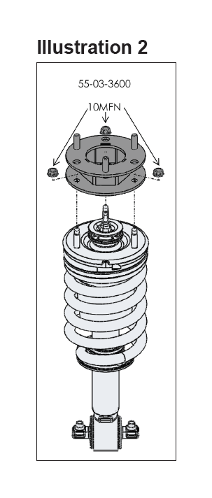
[Illustration 2] Attach the strut spacer bracket (#55-03-3600) to the top of the strut assembly using supplied 10mm flange nuts. Tighten the flange nuts (40).
Note the outermost stud on the strut that was marked during removal now points to the inside of the vehicle. Slide the strut assembly through the upper control arm and locate the upper end of the assembly in the frame mount properly. Secure the upper end of the assembly using the factory hardware. Do not tighten at this time.
Attach the lower end of the strut to the lower control arm using the factory hardware in the forward hole and the supplied 10mm x 65mm bolt in the rearward hole.
Tighten the 10mm hardware at the top (45) and the factory hardware at the bottom (40) of the strut assembly.
9) CONTROL ARM...
Connect the new control arm to the steering knuckle using the supplied castle nut and cotter pin.
Connect the factory brake line bracket to the upper control arm with the supplied 1/4” self-tapping bolt. Note: The bracket may need to be bent slightly to start the bolt; it can be bent back to the original position once the bolt is tightened.
10) TIE ROD ENDS...
Attach the tie rod end to the knuckle using the factory nut and tighten (44).
11) ANTI-SWAY BAR LINKS...
Reattach the anti-sway bar links to the lower control arm and the anti-sway bar body. Tighten until the exposed thread dimension previously recorded is reached.
2WD INSTALLERS SKIP TO STEP 15
12) REAR CROSSMEMBER and DIFFERENTIAL SPACERS...
Mark on the rear crossmember the spot where the front differential is the closest to the rear crossmember.
Remove the rear crossmember. Support the differential with a jack and remove the rear differential bolts.
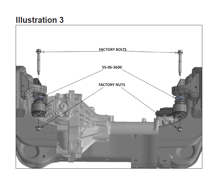
[Illustration 3] Carefully lower the differential enough to install the new thin spacers (#55-06-3600) between the frame and the differential mount and secure using the supplied 10mm x 65mm bolts; do not tighten at this time.
[Illustration 4] Remove the front differential bolts and lower the differential down to enough to install the thick spacers (#55-05-3600) between the frame and the differential mount and secure the supplied 12mm bolts and factory nuts; do not tighten at this time.
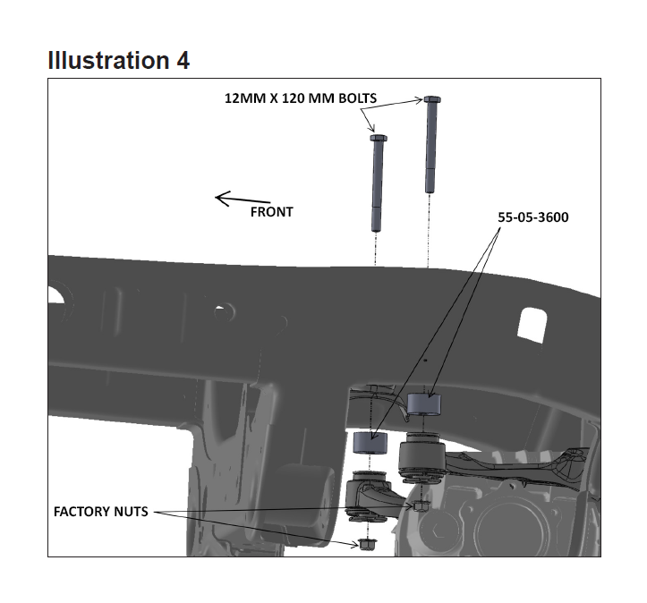
Tighten the rear differential bolts and then the front. (75) It is important to tighten the rear differential bolts first to ensure proper alignment of the differential.
Using the marks made earlier on the rear crossmember as a guide, use a hammer to form a slight depression in the crossmember to allow for clearance around the differential. The depression should be about 1/8” deep.
Reinstall the rear crossmember using the factory hardware. (154). Make sure the differential is no closer than 1/8” from the factory rear crossmember.
13) SKID PLATE (2007-2013 Year Models)...
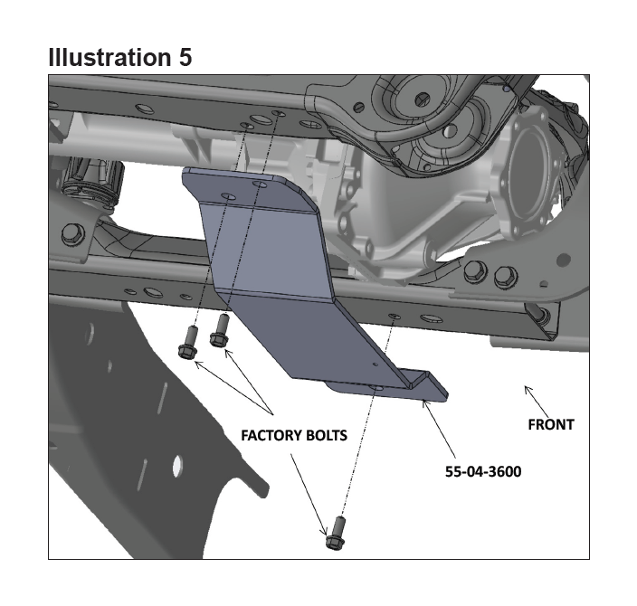
[Illustration 5] Reuse the factory 10mm bolts removed from the upper splash shield and secure the skid plate to the frame. The new skid plate uses one bolt in the front and one in the rear. (40)
Reinstall the plastic splash guard by using the factory hardware at the top and the supplied 10mm x 35mm bolts at the bottom. (30)
14) SKID PLATE (2014 and Newer Year Models)...
[Illustration 5] Reuse the factory 10mm bolts removed from the upper splash shield and secure the skid plate to the frame. (40)
Install the factory passenger side skid plate; placing the supplied spacers (#1-26-7055) between the skid plate and the crossmember. Secure using the supplied 10mm x 35mm bolts. (40)
Reinstall the plastic splash guard by using the factory hardware; only one bolt will be used to attach it to the driver’s side skid plate. (30).
15) TIRES / WHEELS...
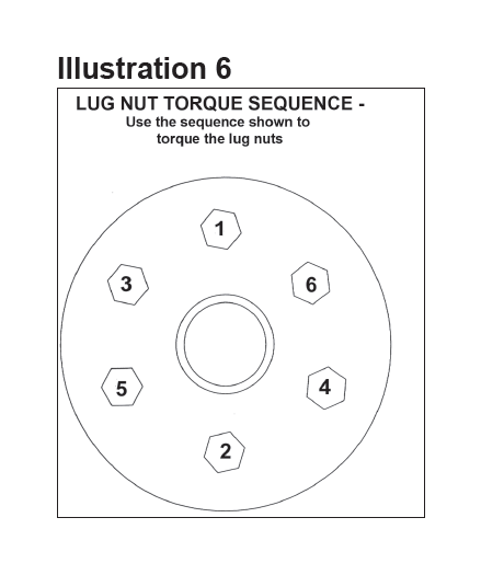
[Illustration 6] Reinstall the tires and wheels. Tighten the lug nuts (95) in the sequence shown.
WARNING: When the tires / wheels are installed, always check for and remove any corrosion, dirt, or foreign material on the wheel mounting surface, or anything that contacts the wheel mounting surface (hub, rotor, etc.). Installing wheels without the proper metal-to-metal contact at the wheel mounting surfaces can cause the lug nuts to loosen and the wheel to come off while the vehicle is in motion.
WARNING: Retighten lug nuts at 500 miles after any wheel change, or anytime the lug nuts are loosened. Failure to do so could cause wheels to come off while vehicle is in motion.
16) INITIAL CLEARANCE CHECK…
With the vehicle still on jack stands, and the suspension “hanging” at full extension travel, check all components for proper operation and clearances. Pay special attention to clearance between the tires / wheels and brake hoses, driveshaft, etc.
Lower vehicle to the floor.
REAR DISASSEMBLY
17) PREPARE VEHICLE...
Place vehicle in neutral. Raise rear of vehicle with a jack and secure a jack stand beneath each frame rail, in front of the rear link arms. Ease the frame down onto the stands, place transmission in low gear or “park”, and chock rear tires. Place jack under axle and raise. Remove rear tires.
18) UBOLTS...
Remove spring to axle U-bolts and move axle several inches away from springs.
Clean spring pads of all debris.
REAR ASSEMBLY
19) BLOCK AND UBOLTS...
Position the Superlift block on top of the factory block, then using the floor jack(s), mate the springs to the blocks, be sure that the center bolt heads seat properly. Install the new Superlift U-bolts and factory U-bolt plate. Evenly torque the U-bolts using an “X” tightening sequence (85).
20) SHOCK ABSORBERS...
Install the rear shock absorbers. Position a supplied 3/4” SAE washer at the top and bottom of the shock on the inside of the bracket and tighten the upper and lower bolts (76).
21) TIRES / WHEELS...
[Illustration 6] Reinstall the tires and wheels. Tighten the lug nuts (95) in the sequence shown.
WARNING: When the tires / wheels are installed, always check for and remove any corrosion, dirt, or foreign material on the wheel mounting surface, or anything that contacts the wheel mounting surface (hub, rotor, etc.). Installing wheels without the proper metal-to-metal contact at the wheel mounting surfaces can cause the lug nuts to loosen and the wheel to come off while the vehicle is in motion.
WARNING: Retighten lug nuts at 500 miles after any wheel change, or anytime the lug nuts are loosened. Failure to do so could cause wheels to come off while vehicle is in motion.
22) CLEARANCE CHECK...
With the vehicle still on jack stands, and the suspension “hanging” at full extension travel, check all components for proper operation and clearances. Pay special attention to the clearance between the tires / wheels and brake hoses, wiring, etc.
Lower vehicle to the floor.
23) FOUR WHEEL DRIVE...
Activate four wheel drive system and check front hubs for engagement.
24) HEADLIGHTS...
Readjust headlights to proper setting.
25) SUPERLIFT WARNING DECAL…
The WARNING TO DRIVER decal installs on the inside of the vehicle within the driver’s view. Prior to installation, pre-clean the surface with the supplied alcohol cleaning pad.
26) SUPERLIFT BADGES...
This kit is packaged with a Superlift badge. Prior to installation, use the supplied alcohol pad to eliminate all soap and or other non-adhering residues that may impair adhesion, thoroughly clean the entire area of placement.
Remove the adhesive back and place small badge in the desired location. The adhesive on our badges is pressure sensitive and must be applied using pressure on all areas of the graphic. Like any PSA (pressure sensitive adhesive), it can take up to 72 hours for the adhesive to fully cure. Once the badge is in place do not peel it up, this will diminish the adhesive properties and could result in damaging the badge itself
To keep your Superlift badge in “like new” appearance keep the badge free/clear of solvents and chemicals that could cause the adhesive to dry or dissolve. This includes gasoline, diesel fuel, paint thinner, and alcohol. Soap and water is all that is needed for cleaning. Degreasers can be used sparingly and hand wiped/applied if needed, although not suggested.