 FREE 1 to 3-Day Delivery on Orders $149+ Details
How to Install SuperLift 2.5 in. Front Torsion Key Leveling Kit (97-03 4WD) on your Ford F-150
Shop Parts in this Guide
INTRODUCTION - Installation requires a professional mechanic. Prior to beginning, inspect the vehicles steering, driveline, and brake systems, paying close attention to the control arms and bushings, anti-sway bars and bushings, steering linkage, pitman arm, ball joints and wheel bearings. Also check the steering sector-to-frame and all suspension-to-frame attaching points for stress cracks. The overall vehicle must be in excellent working condition; repair or replace all worn parts.
Read instructions several times before starting. Be sure you have all needed parts and know where they install. Read each step completely as you go.
NOTES:
• Prior to beginning the installation, check all parts and hardware in the box with the parts list below. If you find a packaging error, contact Superlift® directly. Do not contact the dealer where the system was originally purchased. You will need the control number from each box when calling; this number is located at the bottom of the part number label and to the right of the bar code.
• Front end realignment is necessary.
• A foot-pound torque reading is given in parenthesis ( ) after each appropriate fastener.
• Do not install any additional components or modify this system to gain additional suspension height.
• Prior to attaching components, be sure all mating surfaces are free of grit, grease, undercoating, etc.
• A factory service manual should be on hand for reference.
• Speedometer recalibration is recommended if a taller tire is used.
• Use the check-off box “” found at each step to help you keep your place. Two “” denotes that one check-off box is for the driver side and one is for the passenger side.
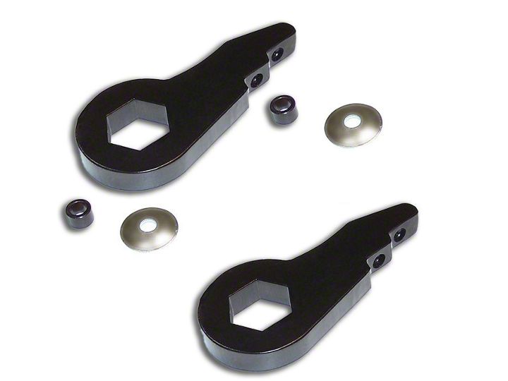
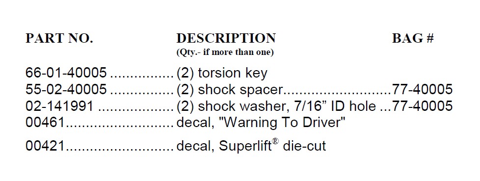
PARTS LIST… The part number is stamped into each part or printed on an adhesive label. Identify each part and place the appropriate mounting hardware with it.
NOTE: Save all factory components and hardware for re-use unless otherwise noted.
1) PREPARE VEHICLE... Place the vehicle in neutral. Raise the front of vehicle with a jack
and secure a jack stand beneath each frame rail, behind the lower control arms. Ease the frame down onto the stands, place transmission in low gear or “park”, and chock rear tires.
2) SHOCK ABSORBERS, CONTROL ARMS… Perform this step one side at a time.
Remove the nut from the top of the shock stem followed by the upper bushing half. Press the shock stem down and out of the frame mount. Remove the remaining bushing half.
An eccentric cam bolt assembly attaches each leg of the upper control to the frame; the cam bolts are also used for front end alignment. Loosen (do not remove) the cam bolts. Prior to loosening, mark the cam washers’ orientation, in relation to the control arm, for later reference.
3) UNLOADING THE TORSION BARS… Perform this step one side at a time.
WARNING: Be extremely careful when loading / unloading the torsion bars; there is a tremendous amount of energy stored in them. Keep your hands and body clear of the torsion bar / key assembly and the puller tool in case anything slips or breaks. Use a C-clamp type puller designed for this application. If using Superlift® tool #40017, be sure to also use the adapter (included with tool), designed to help keep the upper end of the tool in position on top of the crossmember.
IMPORTANT: Lubricate the puller tool bolt prior to use.
Position the tool. Load the torsion bar then remove the adjusting bolt and nut block. Unload the bar.
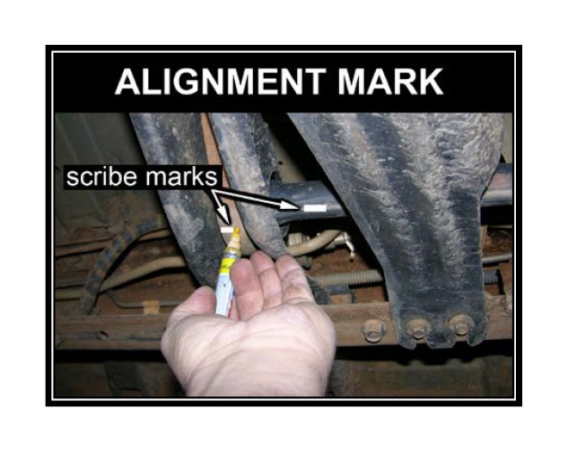
Prior to removing the key from the bar, scribe an alignment mark on the bar and factory torsion key to note how they are indexed in relation to each other.
Slide the torsion bar forward into the lower control arm enough to remove the torsion key.
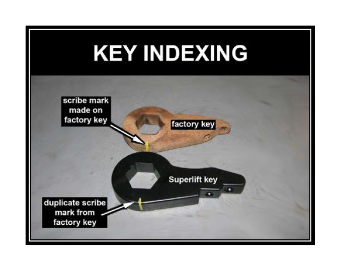
4) NEW TORSION KEYS… [SEE DIAGRAM - KEY INDEXING] Perform this step one side at a time.
Determining proper key-to-bar indexing - Position one of the factory torsion keys on a flat surface (work bench or floor), with the scribe mark, made in step 3, facing up. Position a Superlift® key on top of the factory key. Align the “flats” of the hex holes so that the opposite ends of both the keys remain as close to each other as possible. Now scribe a mark, as shown, on the Superlift® key.
Position the new torsion key inside the crossmember then mate the bar-to-key. Make sure the bar and key are properly indexed by aligning the scribe marks.
Coat the adjusting bolt with an anti-seize type lubricant. Load the torsion bar. Insert the factory nut block into the crossmember. Install the factory adjusting bolt; leave approximately 1” of adjustment bolt threads visible below the nut block. Unload the tool. Final ride height adjustments are made once the vehicle is on the floor.
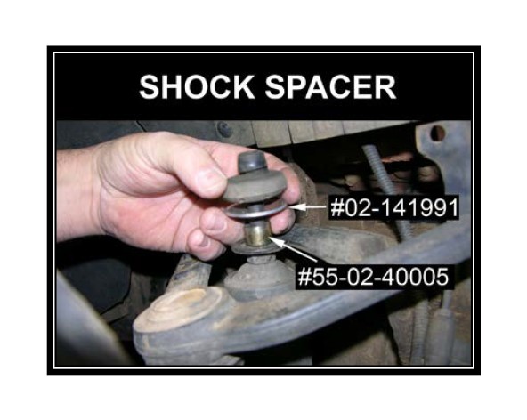
5) SHOCK ABSORBERS… Perform this step one side at a time.
Slide the supplied shock spacer #55-02-40005 over the stem end of the shock followed by the supplied shock washer #02-141991. Place the factory bushing half on top of the shock washer then attach the upper end of the shock-to- frame using the remaining factory hardware. Tighten until bushings swell slightly.
6) INITIAL CLEARANCE CHECK... With the vehicle still on jack stands, and the suspension “hanging” at full extension travel, cycle steering lock-to- lock and check all components for proper operation and clearances. Pay special attention to the clearance between the tires / wheels and brake hoses, wiring, etc.
7) UPPER CONTROL ARM BOLTS… Lower vehicle to the floor. The suspension is now supporting vehicle weight. Prior to tightening the upper control arms eccentric cam bolts, realign the cams using the scribe marks made in step 2 during disassembly (83-112).
8) ADJUSTING FRONT RIDE HEIGHT...
Lower vehicle to the floor. The suspension is now supporting vehicle weight.
With the vehicle on a level surface, manually “bounce” the front of the vehicle to normalize (settle) the torsion bars.
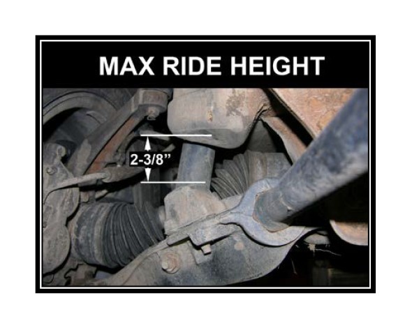
CAUTION: Do not exceed maximum ride height. [SEE PHOTO] As ride height increases, so does the distance between each compression travel dampener and its contact point located on the rear leg of each lower control arm. The distance between the dampener and lower control arm must not exceed 2-3/8”, as shown. If this measurement is exceeded, ride quality will suffer, and the shock absorbers will be subjected to increased loads. Ride height is controlled via the torsion bar adjusting bolts. Increase height by tightening the bolts; decrease height by loosening the bolts. Verify that ride height is equal side-to-side. It is not unusual for one adjusting bolt to require more adjustment than the other.
9) FINAL CLEARANCE and TORQUE CHECK... With vehicle on floor, cycle steering lock-to-lock and inspect the tires / wheels, and the steering, suspension, and brake systems for proper operation, tightness, and adequate clearance.
10) HEADLIGHTS... Readjust headlights to proper setting.
11) SUPERLIFT® WARNING DECAL... Install the WARNING TO DRIVER decal on the inside of the windshield, or on the dash, within driver’s view. Review the “IMPORTANT PRODUCT USE AND SAFETY INFORMATION / WARNINGS" text found at the end of this Instructions sheet.
12) ALIGNMENT... Realign vehicle to factory specifications. Below, record the ride height measurement at time of alignment. If, in the future misalignment occurs due to the torsion bars settling excessively, alignment can be restored by adjusting-up the bars to their original ride height.
Ride Height - _________________________________________
Measurement points - _____________________________________________
