 FREE 1 to 3-Day Delivery on Orders $149+ Details
How to Install Snow Performance Stage 3 Boost Cooler (11-16 3.5L EcoBoost) on your Ford F-150
Installation Time
2 hours
Tools Required
- Drill
- Stepped drill bit
- Phillips head bit
- Metric wrench set (sizes 8mm-17mm)
- Metric sockets (sizes 7mm, 8mm, and 10mm)
- 1/4” drive ratchet
- Wire stripping and crimping pliers
- Diagonal cutting pliers
- Flat and Phillips screw drivers
- 5mm allen socket ¼” drive or Allen wrench (socket recommended)

Shop Parts in this Guide
Tools:
- Drill
- Stepped drill bit
- Phillips head bit
- Metric wrench set (sizes 8mm-17mm)
- Metric sockets (sizes 7mm, 8mm, and 10mm)
- 1/4” drive ratchet
- Wire stripping and crimping pliers
- Diagonal cutting pliers
- Flat and Phillips screw drivers
- 5mm allen socket ¼” drive or Allen wrench (socket recommended)
Installation Instructions
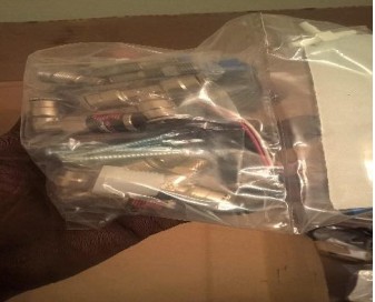
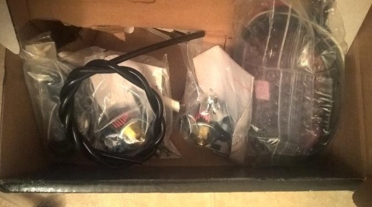
- Open box and ensure all parts are present by checking against the parts list.
- Pop the hood of your vehicle. Disconnect battery
- Decide if you will use supplied reservoir, or vehicle’s washer reservoir to hold your water/meth mixture.
- If using reservoir choose a mounting location for it. (I chose the upper radiator support behind the grille. if you choose to use the same location then proceed to step 4, if not, step 5)
- Remove trim panel on top of radiator
- Install plastic NPT adaptor into bottom of reservoir with sealer on threads, and then 90 degree NPT to push-lock fitting into adaptor with supplied sealer.
- Using step bit, drill ¾” hole approximately 3” from the bottom of the reservoir on the side.
- Feed level sensor wiring into reservoir top and pull through the hole you drilled, until sensor fully seated.
- Place rubber gasket, plastic washer, and then nut onto sensor threads and tighten flush. Connect wires to the LED provided and position it in vehicle as desired.
- Using supplied self-tapping screws and washers, mount reservoir to upper support left of hood latch. Make sure cap of reservoir will clear hood before attaching with screws.
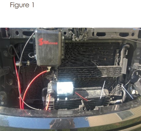
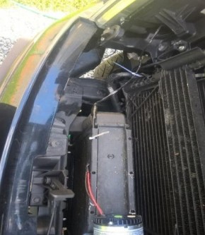
- The highest point should be lower than where the latch on hood rests inside latch assembly on support. (or mount in another desired location, reservoir must be completely higher than pump mounting location to gravity feed) [ Figure 1]
- Remove trim above intercooler and mount pump bracket side down and inlet towards radiator on bracket on top of intercooler using 4 supplied self-tapping screws and washers. (or another desired location, remember that pump must be lower than reservoir. Another good spot is behind the headlight against frame, this makes plumbing for washer tank to be used very easy). [ Figure 1]
- Remove plugs from inlet and outlet of pump.
- Mount solenoids on firewall above manifold using self tapping screws and washers.
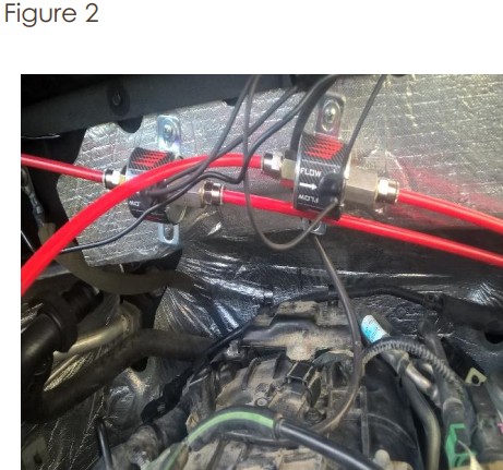
- Orient nozzles with inlet towards passenger of vehicle approximately leaving 6” between them. Install fittings into solenoids with supplied sealer.[ Figure 2 ]
- Remove intake tube coming from air box at clamps using flat head screw driver or 8mm.
- Remove cold side pipe from throttle body using flathead or 8mm and then remove 4 bolts holding throttle body with socket, extension, and ratchet. Discard bolts or keep in case of removal of kit, these bolts will not be re-used (this is a good time to clean your throttle plate, throttle body and intake inlet. They accumulate a lot of buildup).
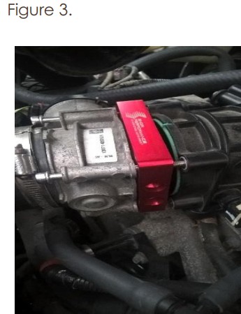
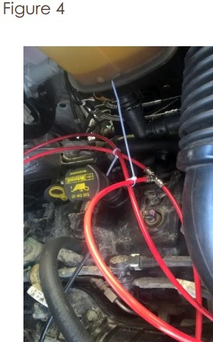
- Place injection plate between intake and throttle body with writing up and o-ring on throttle body side. Install with supplied bolts and washers using a 5mm Allen socket and ratchet. Determine location desired for injection line t-fitting (I placed near front of valve cover on driver side). [ Figure 3 & 4 ]
- Measure tubing to install between sump of reservoir and pump inlet, pump outlet and the inlet of the solenoid used for primary nozzle, outlet of primary nozzle solenoid to tfitting, t-fitting to inlet of solenoid for power nozzle, outlet of power nozzle solenoid to the power nozzle at injection plate, and the final spot on t-fitting to primary nozzle at the injection plate. Make sure to leave enough for turning each line, so that bends are smooth and transitions into each connector have no pressure or stress onto line where it connects, or they may leak.
- Choose desired jets for system (I used #2 and #5). Install filter side into nozzle holder.
- Don’t connect assembled nozzle into plate just yet. Remember the line from the tfitting connects to smaller jetted nozzle and the line from the secondary/power solenoid connects to the nozzle with the larger jet. Use sealer for jet to nozzle connection.
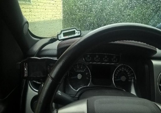
- Mount controller in desired location with supplied double sided tape and route harness through firewall under dash through the grommet above brake pedal. (I mounted it to the top of steering column between the rear of steering wheel and the instrument cluster).
- Connect wiring from controller as follows:
- Red to switched power, Black to negative battery or good body ground,
- Grey to black wire on pump,
- White to red wire on pump and splice with one of the black wires on the primary solenoid (Doesn't matter which wire),
- Green to one black wire on secondary/power solenoid (again either will work).
- The second black wire on both solenoids will go to the negative battery terminal, or to a good body ground.
- Blue wire to FPR signal wire with the supplied wire tap (should be pin marked 35 on inner side of PCM connector closest to passenger side).
- Clear boost tube connects to vacuum line and vacuum line to good boost reference on intake manifold. You can use the rubber molded plastic line on DS of manifold near throttle body, or use the supplied ¼” vacuum tee to tie into the waste gate reference lines in front of MAP sensor.
- Tips: I used the pcv inlet on passenger side of manifold; be aware that this requires a separate adaptor and modification of that system. You can use a separately purchased adaptor that provides a boost fitting that installs between manifold and the map sensor, or you can use another source of manifold pressure. Be careful to pick a good reference spot for optimal performance.
- Tips: As long as the wires are hooked up as stated previously than the system will function as intended. My wiring is as follows, red from controller to a “key on power” fuse in the junction box at top of radiator using the supplied fuse tap, black to battery negative terminal using a supplied connector,, green to black wire on power solenoid using supplied butt connector, blue to FPR signal in pcm main connector using supplied wire tap, boost tube to vac line into adaptor at pcv inlet, white to red pump wire, grey to black pump wire, primary solenoid black wire splice into white wire going to pump power, the second black wire on each solenoid were connected and ran to negative battery terminal.
- Tips: Use electrical tape to cover all connections, route all wires away from heat or interference with mechanical components,
- Tips: secure wires in place with wire ties or similar.
- Tips: Solenoid black wires are non specific and cannot be hooked up backwards, just be sure primary solenoid has wire joined to pump power and power solenoid has a wire connecting to green from controller.
- Tips: Wires from harness may have to be extended according to your chosen component locations. Be prepared to have extra connectors and wire on hand.
- Example pictures of wire routing, connections, etc are on page 6.
- After all connections are made, key on vehicle to ignition. At this time don't start engine, verify that the controller is working.
- Go through setup and choose desire activation settings based on your vehicle and your intended use of system.
- Fill reservoir with 50/50 mix of water/methanol or snow’s boost juice. If using washer fluid, make sure and use only -20 (or better( pre mix with water, methanol, and dye as ingredients only). L2.5 bottles of “Heet” will bring mixture to approximately 50/50 when mixed with generic -20 degree washer. Don’t use washer fluids that have other ingredients added, such as soaps.
- After wiring is completed, re-connect battery. Use regulated shop air, set at or below 50 psi, to pressurize boost reference hose with approximately 30 psi to trigger pump. Do this with key on engine off.
- Pressurize system until liquid streams constant and smoothly from both nozzles to bleed air.
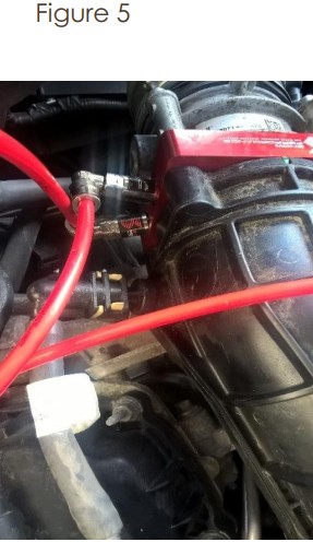
- Install nozzles into the injection plate with supplied sealer. Figure 5
- Drive vehicle to test system operation.
- Enjoy your Snow Performance stage 3 system!
Reference Figures for installation
wiring harness routing examples
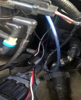
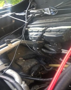
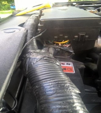
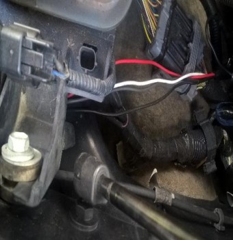
Installation instructions written by American Muscle customer Daniel
Taylor 09.19.17

