FREE 1 to 3-Day Delivery on Orders $149+ Details
How to Install Roush Power Pac - Level 2 on your F-150
Installation Time
3 hours
Tools Required
- Metric 1/4" Drive Socket Set
- Flat-head Screwdriver
- Trim Tool
- Pliers
- Drill
- 17/64" Drill Bit
- Center Punch
- Metal-Cutting Device (Band Saw, Hack Saw, Cut-off Wheel)
- Ratchet with Extensions
- Metric Socket Sets (deep recommended)
- Torque Wrench
SECTION A – REMOVAL
The following section will guide you through the removal of the stock components. Special care should be taken to label fasteners and parts that are taken off during this procedure since many will be reused.
1. Cover both fenders with fender covers to protect the vehicle fi nish.
2. Disconnect the battery ground cable.
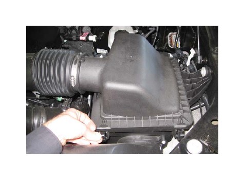
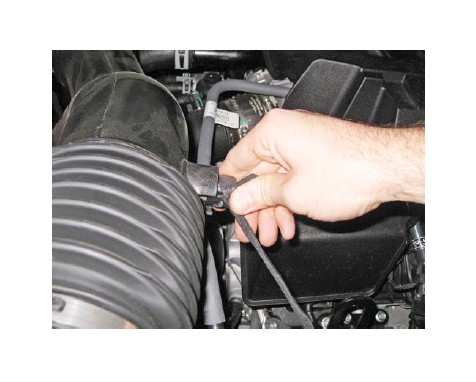
3. Release both clips holding the lid on the air box.
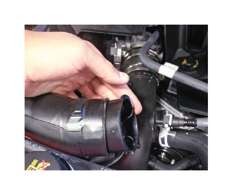
4. Loosen the clamp between the clean air tube and the passenger side turbo inlet.
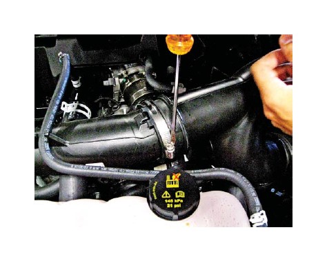
5. Loosen the clamp between the clean air tube and the driver side turbo inlet.
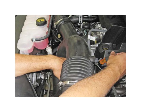
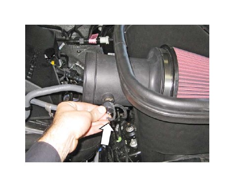
6. Remove the IAT by twisting the sensor.
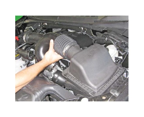
7. Remove the clean air tube and air box lid from the vehicle.
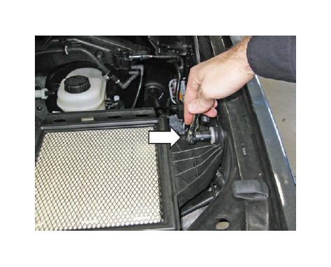
8. Remove the bolt retaining the stock air box to the inner driver side fender. Retain the bolt, sleeve and grommet for later use.
9. Remove the two (2) push clips retaining the dirty air inlet duct to the grill closeout.
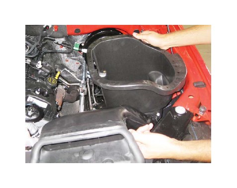
10. Remove the lower air box and dirty air duct from the vehicle.
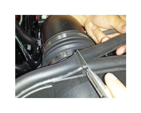
11. Remove the self-tapping screw retaining the dirty air inlet onto the lower air box.
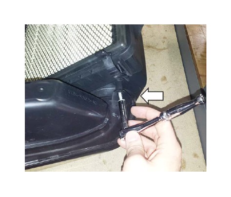
12. Remove the dirty air inlet from the lower air box.
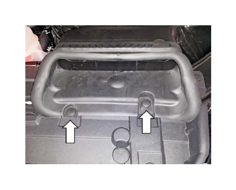
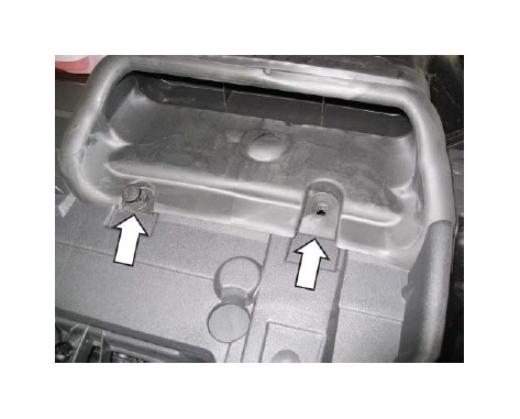
13. If necessary, remove the two (2) rubber grommets from the bottom of the air box and reinstall them into the tray below the air box.
SECTION B — INSTALLATION
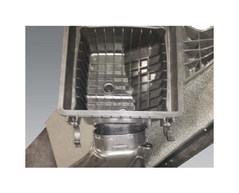
1. Insert the dirty air inlet into the Roush air box (P/N: 1115-9A612). Reuse the self-tapping screw that was removed earlier. Tighten to 3 Nm.
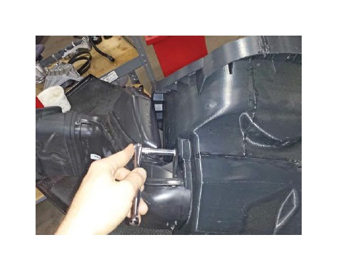
IMPORTANT: Do not remove the shown silencer rings.
2. Reinstall the bolt, grommet and sleeve into the driver side fender. Tighten the bolt to 17.5 Nm.
2015-2016 F-150 proceed to step 9.
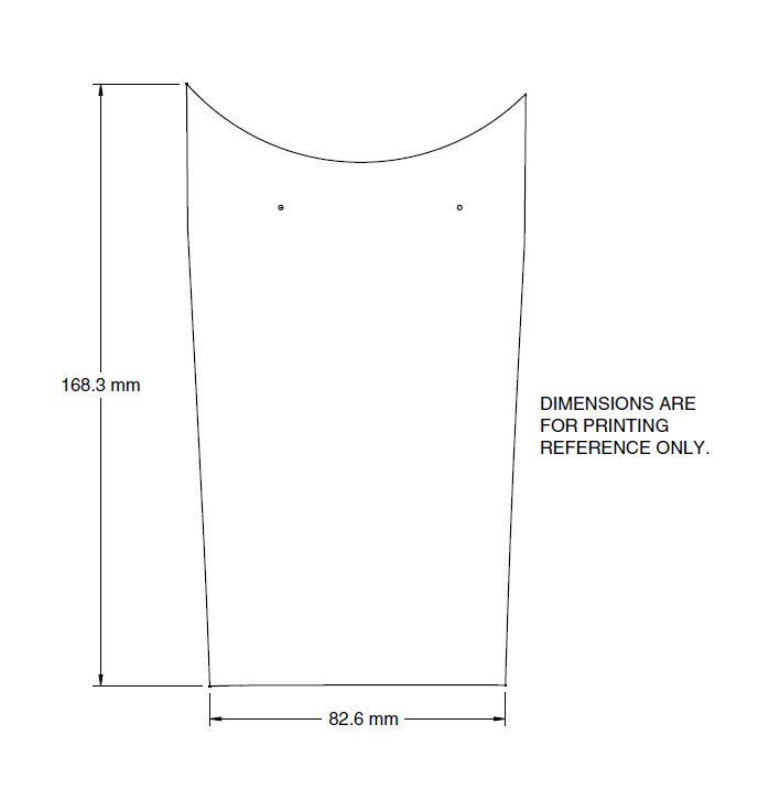
3. Print out the template and make sure the dimensions are correct. Cut out the template.
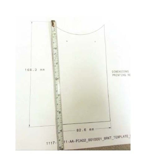
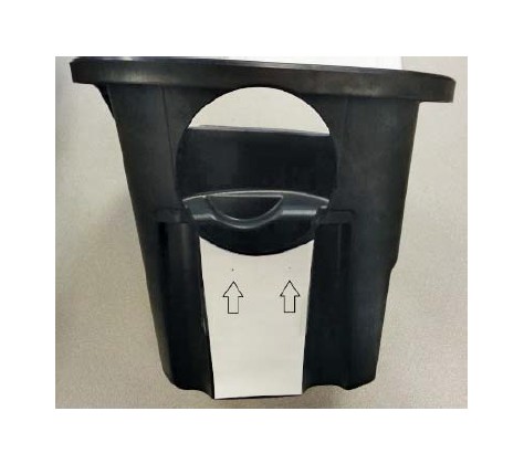
4. Tape the template to the side of the air box. Use a punch to mark the two (2) drill holes.
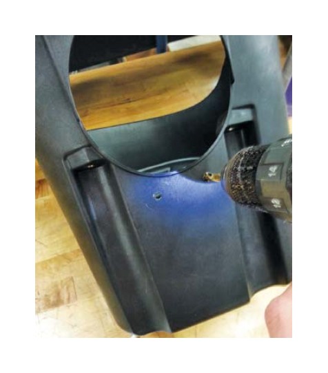
5. Drill the holes out using a 17/64” drill bit.
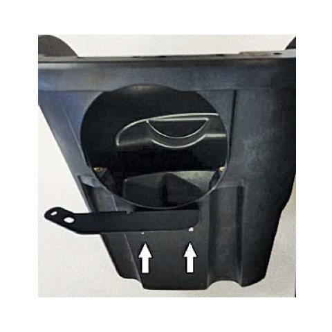
6. Mount the bracket (P/N: 117-9B611) to the outside of the air box using two (2) M6 bolts (P/N: W500013-S307). Torque to 10 Nm.
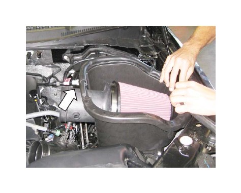
7. Install the Roush airbox into the truck by locating the two (2) bosses on the bottom of the box while aligned to the grommet.
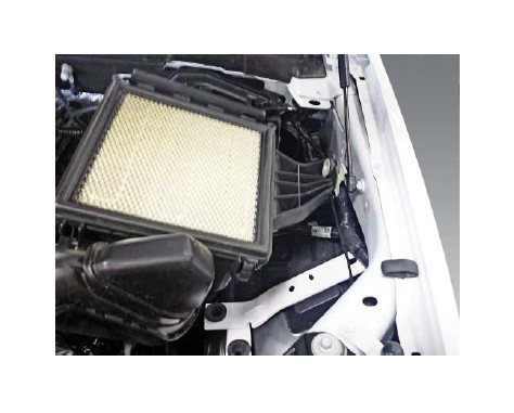
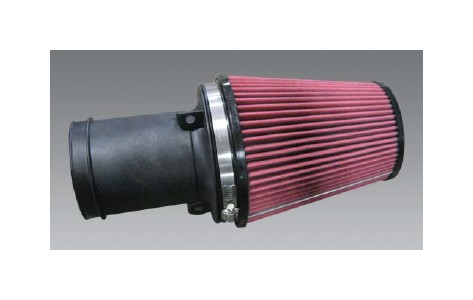
8. Install the air fi lter (P/N: 131550-9601R) onto the fi lter tube (P/N: 111550-12B579) and tighten the clamp to 3 Nm. Make sure the fi lter is installed (as shown) with the metal rib down.
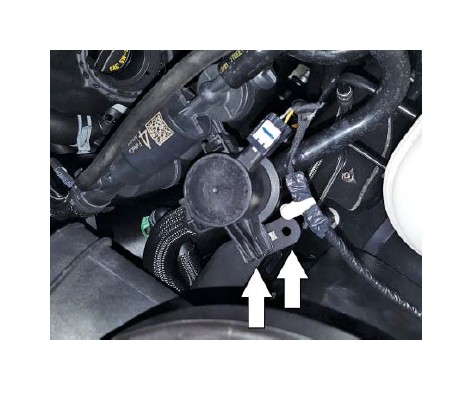
9. Slide the fi lter and tube assembly into the air box. Twist the IAT sensor into the port as shown. NOTE: 2017 F-150 use the IAT sensor jumper harness (P/N: 117-12A690) to connect the IAT sensor.
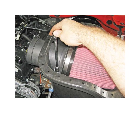
10. Install the two (2) M8 bolts (P/N: W500224-S437) and tighten to 10 Nm.
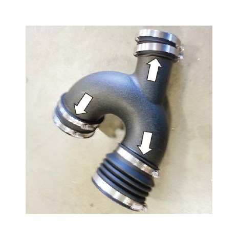
11. Install couplers and clamps onto the clean air tube (P/N: 1115TT-9B660) as shown. Tighten the clamps retaining the coupler to the tube to 3 Nm. Leave the outside clamps loose (coupler: top P/N: 1115TT-9B663, bottom P/N: 1115TT- 9B661, left P/N: 1115TT-9B662) (clamps: top P/N: R07130028-13, bottom P/N: R07130015-13 and P/N: R07130028-13, left P/N: 308707426).
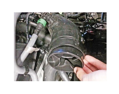
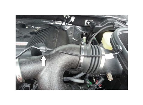
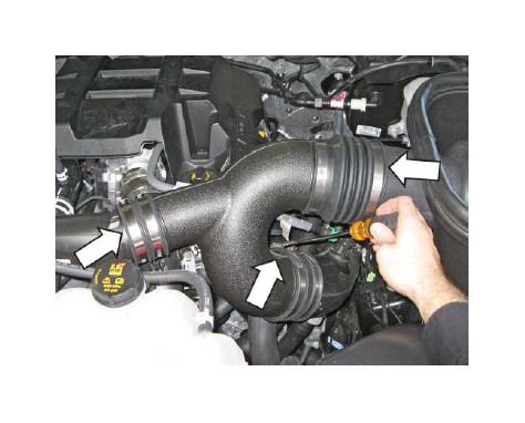
12. Install the clean air tube assembly between the throttle body and the air box. Tighten the clamps to 3 Nm.
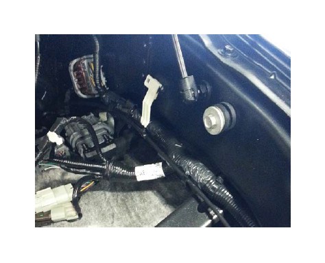
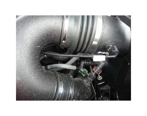
13. Clip the harness and vacuum line into position on the air box bracket.
14. Reinstall the two (2) push pins into the dirty air inlet.
15. Insert the seal fi ller (P/N: 1115-9B624FOAM) halfway into the air box seal (P/N: 1115-9B624) as shown.
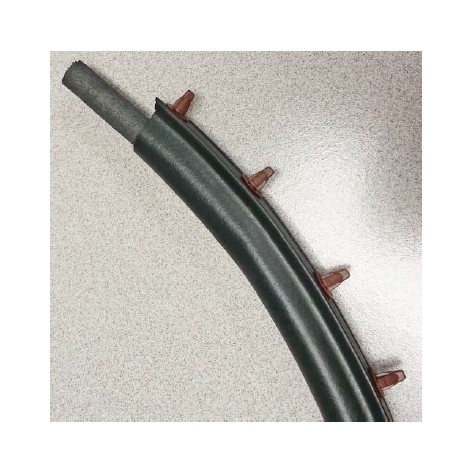
16. Install the air box seal starting in the location shown. You may need to trim your seal to the correct length. (NOTE: Start the seal at the middle of the inlet tube.)
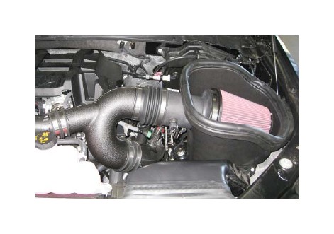
17. The installation is now complete.
PCM FLASHING
Proceed with steps 1-2 if you have a SAE J2534 pass through device (e.g. Puma, VCM I, VCM II)
If you do not have a SAE J2534 device visit your local Roush Dealer or Performance Shop with the appropriate tools for PCM Calibration
1. If equipped with a SAE J2534 pass through device, refer to the RDT-CALIM manual found on our website. http://rdt.roush.com The RDTCALIM manual will guide you through the ROUSH Diagnostic Tool (RDT) software installation process and the ROUSH PCM fl ashing procedure detailed in RDT-CALIM.
2. Once the PCM has been successfully recalibrated, start the engine and check for unusual noises, dash service lights, and unusual operation. If problems are detected, immediately stop the engine or vehicle, diagnose and repair the problem.
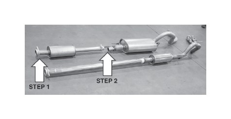
SECTION A – DISASSEMBLY
The following section will guide you through the disassembly and removal of the stock components. Longer wheelbase vehicles will also have an intermediate pipe (not shown) between the factory resonator and the muffl er.
1. Remove the two (2) bolts that secure the intermediate pipe and resonator to the catalyst pipe. Set these fasteners aside as they will be re-used.
2. Loosen the clamps that secure the intermediate pipe and resonator to the muffl er and tail pipes.
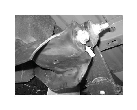
3. Remove the hanger in the center of the vehicle at the rear of the muffl er. This will aid in removing and installing the exhaust components.
4. Remove the intermediate pipe and resonator from the vehicle.
5. Slide each of the hangers out of the rubber hangers and remove the factory muffl er/tail pipe assembly from the vehicle.
SECTION B – ASSEMBLY
The following section will guide you through the assembly and installation of the ROUSH components.
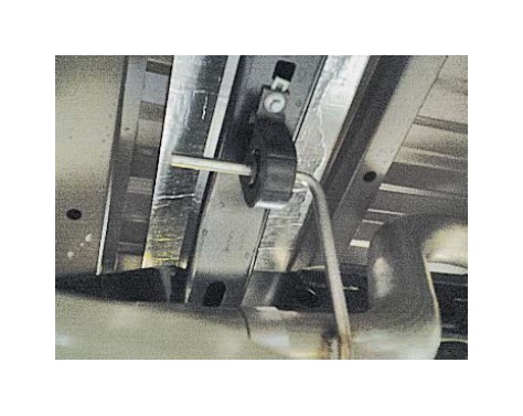
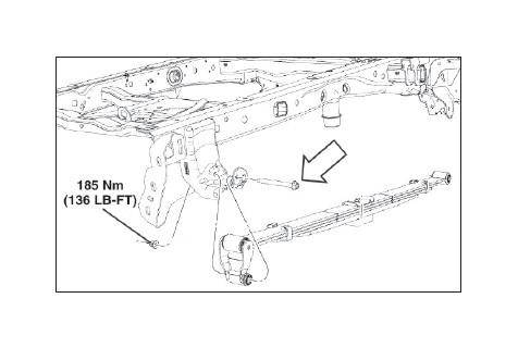
1. Loosen the rear spring support bracket bolt so that there is a gap of about 7-10 mm of threads showing.
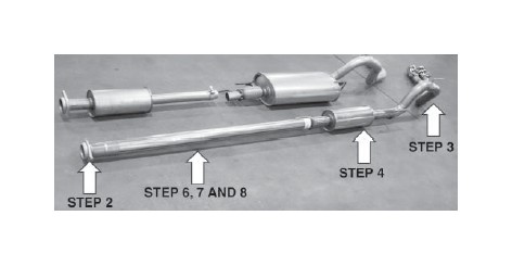
2. Position the new catalyst pipe adapter fl ange into place against the catalyst pipe and loosely install the two (2) take-out fasteners to hold it in place.
3. Position the new muffl er outlet axle pipe into position and install the steel hanger brackets into the factory rubber hangers. Orient the pipe such that the fl ared end faces forward in vehicle. At this time, re-install the hanger bracket that was removed in step 3 of the Disassembly section.
4. Insert one (1) 3" clamp over the outlet end of the new muffl er assembly and slide this into the end of the muffl er outlet pipe. Position the clamp on the joint and loosely secure.
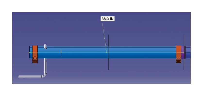
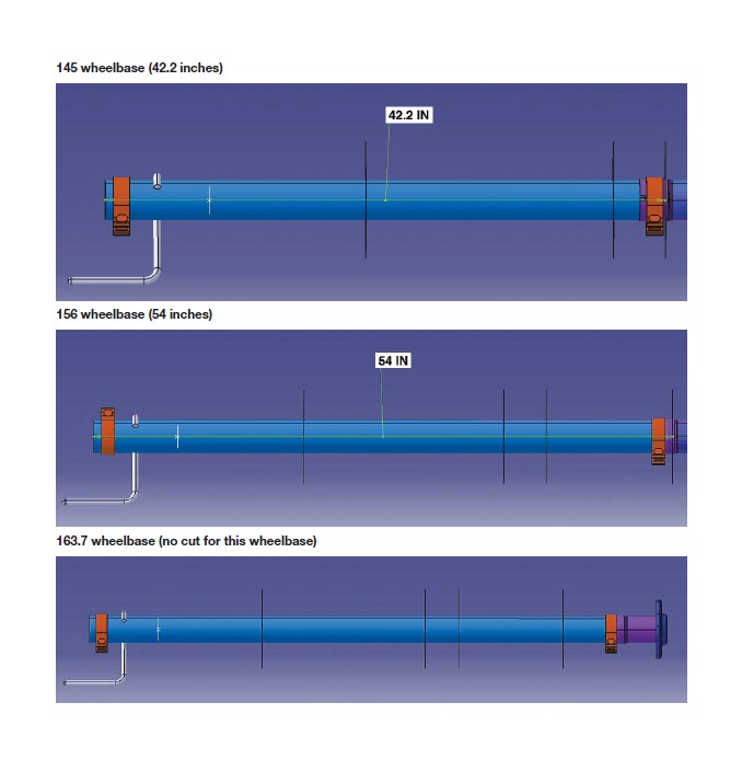
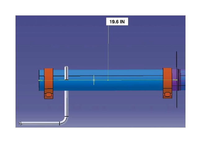
5. There is a list of the cut lengths for this intermediate pipe at the end of this document. Be sure to leave enough length for engagement into the catalyst pipe fl ange. Mark the pipe and double check BEFORE cutting to ensure it will be cut correctly.
NOTE: This intermediate pipe has to be cut to length prior to fi nal installation to fi t your particular vehicle wheelbase.
6. Remove the intermediate pipe and cut the pipe at the marked length to fi t your wheelbase. Make sure to double check your measurement prior to cutting the material. Cut off the end OPPOSITE the hanger that is welded to the pipe. Remove all sharp edges after cutting.
7. Re-install the pipe assembly to the catalyst fl ange. Loosely install the two (2) fasteners.
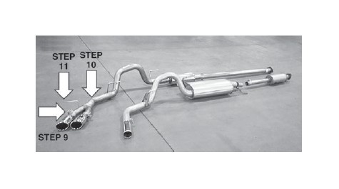
8. Install one (1) 2.5" clamp onto each of the exhaust tips and slide the tips onto the ends of the Y-pipe. Position the clamps on the pipe joints and loosely secure the clamps.
9. Insert one (1) 3" clamp over the end of the new Y-pipe assembly and slide into position on the end of the muffl er outlet pipe.
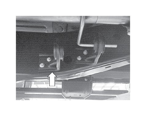
10. Insert the Y-pipe hanger into the hanger bracket. It is important to note the orientation of the bracket as it will hang underneath the suspension bracket.
11. Slide the new rear tailpipe support bracket between the head of the bolt and the frame. Retorque the bolt to 185 Nm. When torquing the leaf spring bolt, this must be done with the vehicle on the ground, not on a hoist. The vehicle must be under its own weight.
12. With the full system now hanging in the vehicle, make sure all of the hangers are fully seated and there are no clearance issues with vehicle parts contacting the exhaust system.
13. With the system in the desired position, torque all four (4) 3" clamp joints to 50 Nm.
14. Torque the two (2) catalyst adapter bolts to 44 Nm.
15. Torque the two (2) 2.5" clamps on the tips to 50 Nm. 16. On the eco-boost vehicle, there are two (2) hangers at the muffl er. The most forward hanger can be removed. Store this with your stock takeoff exhaust.
Congratulations!!! You have completed the installation of your new ROUSH Performance Products, F-150 Off-Road Exhaust Kit. It is recommended that you save all parts removed from your vehicle during the installation of this kit.
CUT LENGTHS PER WHEELBASE122.4 wheelbase (19.6 inches)
141.1 wheelbase (38.3 inches)