FREE 1 to 3-Day Delivery on Orders $149+ Details
How to Install Roush Fender Flares (15-17 All, Excluding Raptor) on your Ford F-150
Tools Required
- Isopropyl Alcohol
- 5.5 mm Socket
- 8 mm Socket
- Marker
- Drill Motor
- 11/16” Drill Bit
- Trim Tool
- Terry Cloth
- 7 mm Socket
- 10 mm Socket
- #2 Phillips Head Driver
- 1/4” Drill Bit
- Automotive Clear Coat

Shop Parts in this Guide

SAFETY PRECAUTIONS
CAREFULLY READ THE IMPORTANT SAFETY PRECAUTIONS and WARNINGS BEFORE PROCEEDING WITH THE INSTALLATION!
Appropriate disassembly, assembly methods and procedures are essential to ensure the personal safety of the individual performing the kit installation. Improper installation due to the failure to correctly follow these instructions could cause personal injury or death. Read each step of the installation manual carefully before starting the installation.
• Always wear safety glasses for eye protection.
• Place ignition switch in the OFF position.
• Always apply the parking brake when working on a vehicle.
• Block the front and rear tire surface to prevent unexpected vehicle movement.
• If working with a lift, always consult vehicle manual for correct lifting specifi cations.
• Operate the engine only in well-ventilated areas to avoid exposure to carbon monoxide.
• Do not smoke or use fl ammable items near or around the fuel system.
• Use chemicals and cleaners in well-ventilated areas.
• Batteries produce explosive gases, which can cause personal injury. Therefore, do not allow fl ames, sparks or
fl ammable substances to come near the battery.
• Keeps hands and any other objects away from the radiator fan blades.
• Keep yourself and your clothing away from moving parts when the engine is running.
• Do not wear loose clothing or jewelry that can get caught in rotating parts or scratch surface fi nishes.
• Allow the engine, cooling system, brakes and exhaust to cool before working on a vehicle.
WORK SAFELY!
Perform this installation on a good clean level surface for maximum safety and with the engine turned off.
DISASSEMBLY
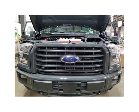
The following manual will guide you through the installation of the 2015 F-150 ROUSH F-150 Fender Flares (P/N: R1115-FFLARE).
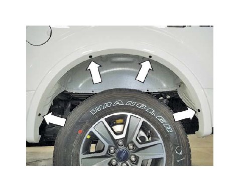
1. Begin by removing three (3) push pins with a trim tool and two (2) fasteners with a 5.5 mm socket from each of the factory front wheel lip moldings (if equipped).
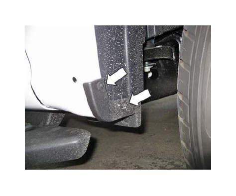
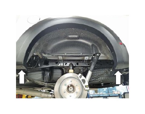
2. Remove two (2) fasteners with a 7 mm socket from the rear of each front wheel well.
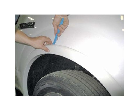
3. Pull fi rmly outwards on the wheel lip moldings (if equipped) to remove them from the front fenders. Use a non-marring trim tool if needed.
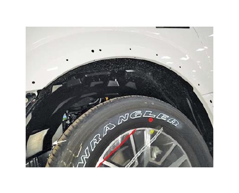
4. Remove any remaining clips with a non-marring trim tool.
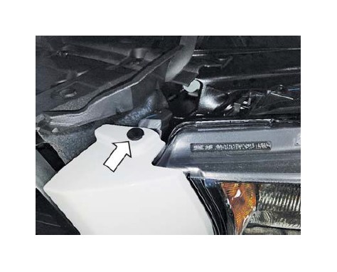
5. Remove one (1) push pin from the top of each headlight assembly trim ring. Carefully release the outer section of each trim ring and then pull them forward to release them.
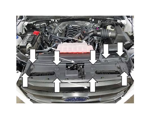
6. Remove nine (9) push pins and set the radiator close out panel aside.
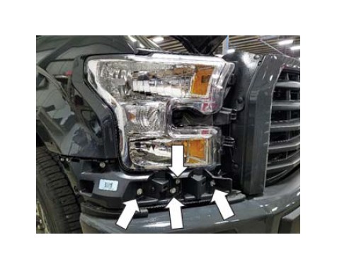
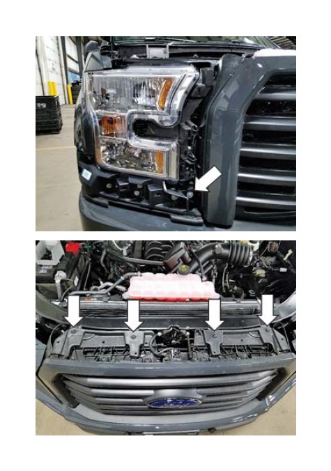
7. Remove one (1) pushpin and six (6) screws with a 10 mm socket. Remove one (1) screw with an 8 mm socket. Disengage the retaining tabs and remove the large plastic bracket below the passenger side headlight.
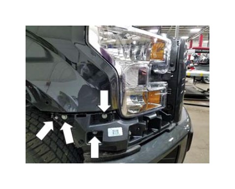
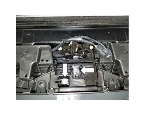
8. Remove two (2) screws with a 10 mm socket which retain the headlight. Disconnect the electrical connectors and set the headlight aside in a safe place.
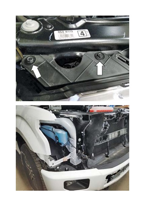
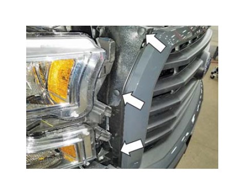
9. Remove three (3) push pins with a trim tool and one (1) screws on each side of the grille with an 8 mm socket. Remove four (4) screws on top of the grille with a 10 mm socket. Disconnect the electrical connectors and remove the front grille assembly.
10. Remove two (2) screws from the bottom side of the factory rear wheel well moldings with a 10 mm socket. Using a non-marring trim tool, remove four (4) push pins from each of the factory rear wheel well moldings (if equipped).
11. Firmly pull outwards on the factory rear wheel well moldings to remove them from the bed sides.
12. Remove any remaining clips using a non-marring trim tool.
SUB ASSEMBLY
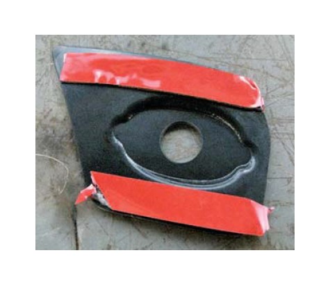
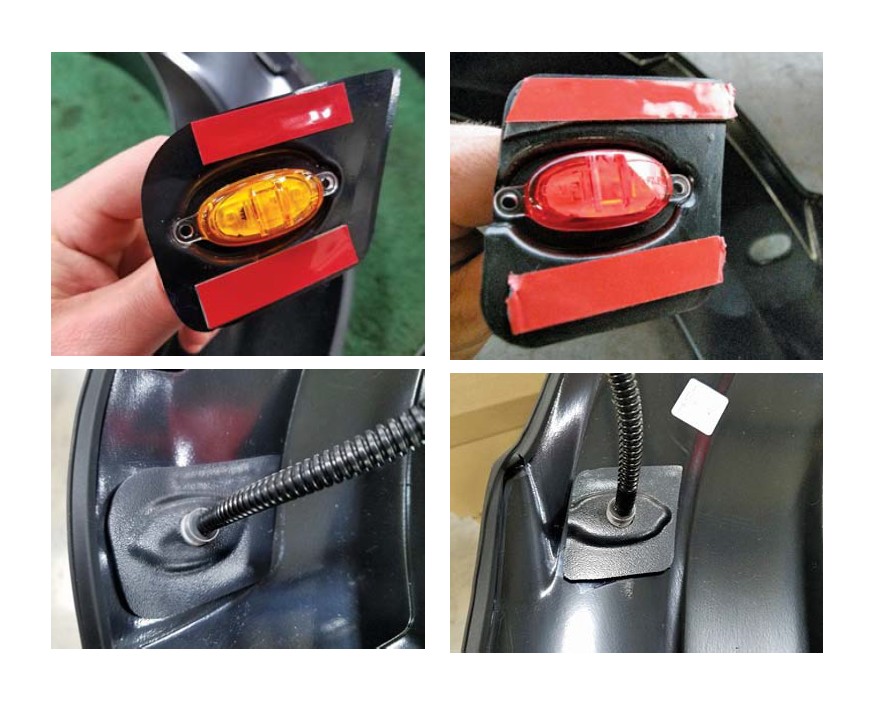
1. Wipe the back of each marker light bracket with the supplied adhesion promoter packet (P/N: 021200-27571). Install (2) pieces of the doublesided acrylic tape (P/N: EX4015x12.5) to the back of each marker light bracket as shown below.
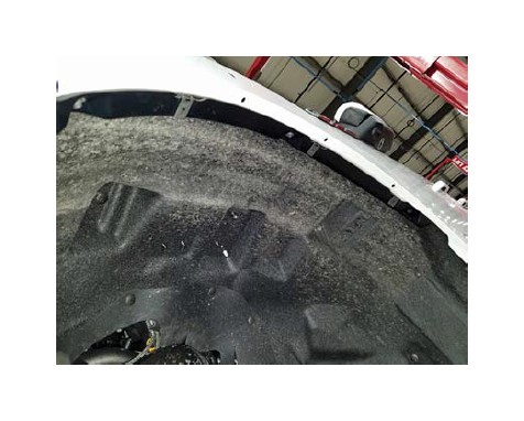
2. Wipe the back of each fender fl are with the supplied adhesion promoter packet (P/N: 021200- 27571) as shown.
3. Install one (1) amber marker light assembly (P/N: 1115-AMBLTE) into each of the front marker light brackets. Remove the red backing from each piece of tape and secure the assembly to each front fender fl are as shown.
4. Install one (1) red marker light assembly (P/N: 1115-REDLTE) into each of the rear marker light brackets. Remove the red backing from each piece of tape and secure the assembly to each rear fender fl are as shown.
WIRE HARNESS INSTALLATION
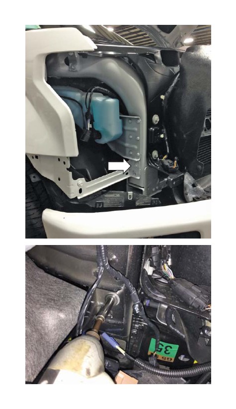
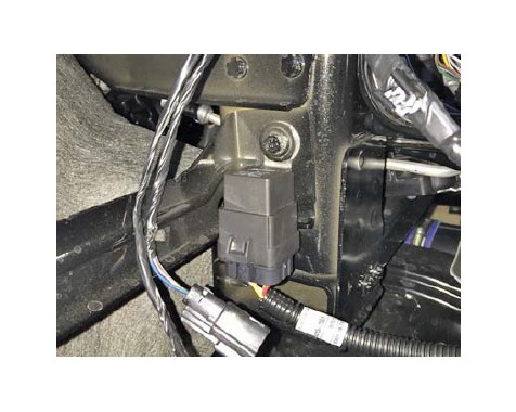
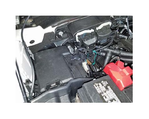
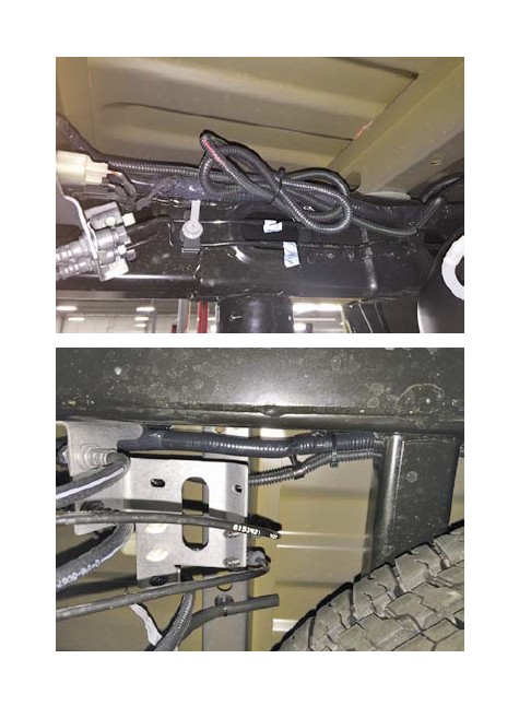
1. Remove one (1) fastener with a 10 mm socket and install the wire harness relay in the location shown. Torque to 8-10 Nm.
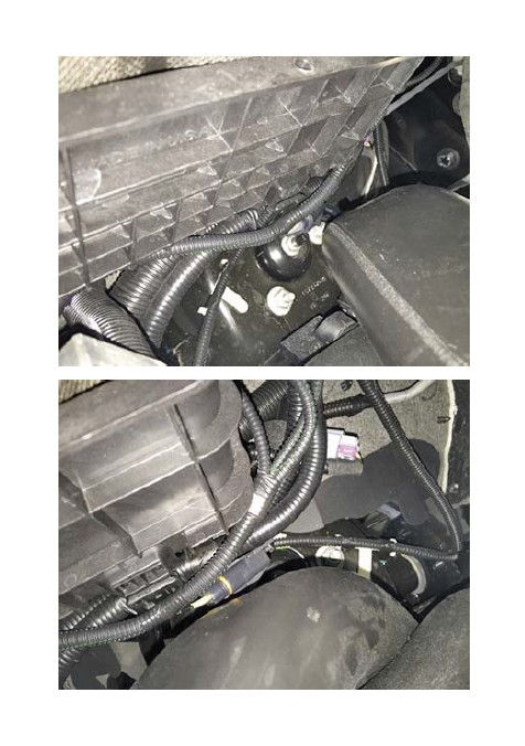
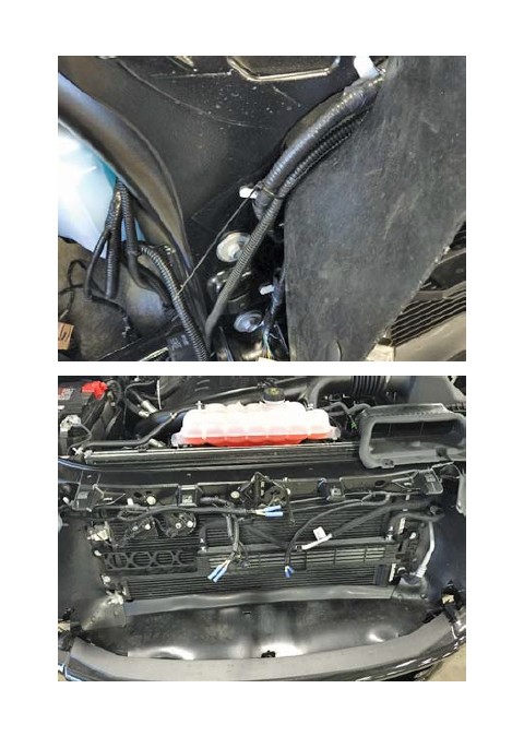
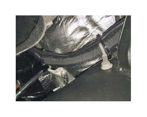
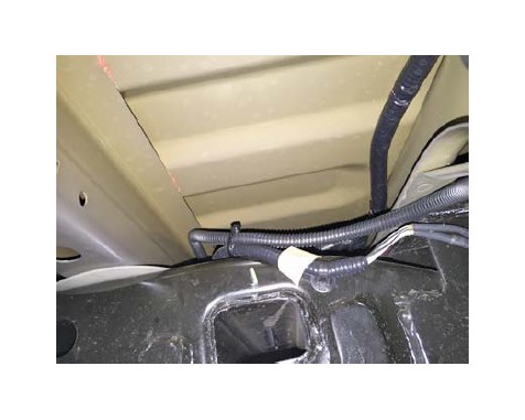
2. Route the two (2) ring terminals and the fuse tap up along the factory harness that passes over the windshield solvent bottle as shown. Secure with the included zip ties (P/N: CTUV740).
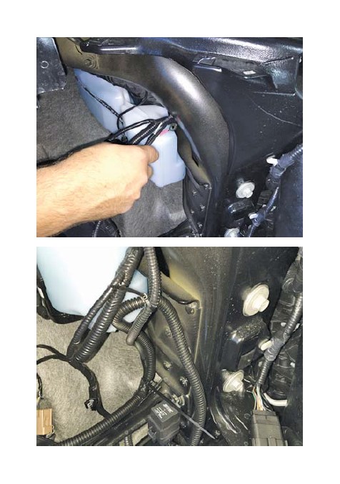
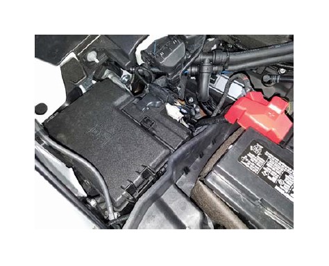
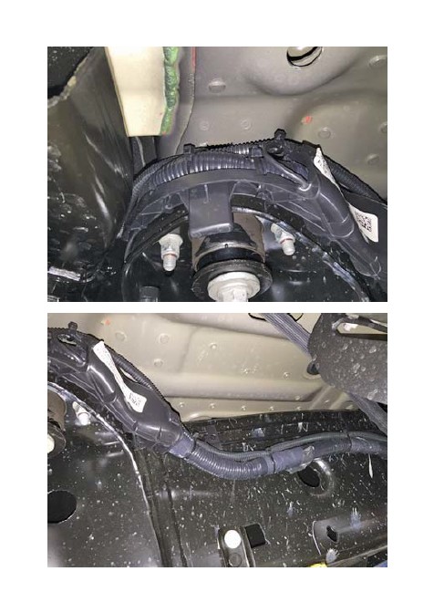
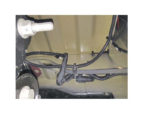
3. Route the two (2) ring terminals and the fuse tap up along the battery box. Secure the fuse plug and harness with the supplied zip ties (P/N: CTUV740) as shown.
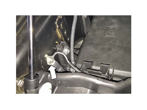
4. Remove one (1) screw with a 7 mm socket. Install the ground ring terminal from the marker light wiring harness (P/N: 1115-15N515). Re-secure the screw that was removed. Torque to 8-10 Nm.
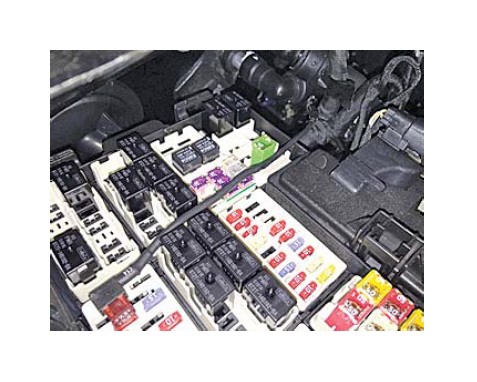
5. Remove the positive terminal cover from the fuse box.
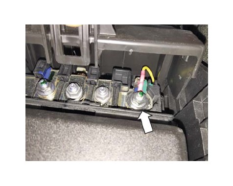
6. Remove one (1) nut with a 10 mm socket from the front positive terminal post. Install the positive ring terminal from the marker light wiring harness (P/N: 1115-15N515) and re-secure the 10 mm nut that was removed. Torque to 8-10 Nm.
7. Remove the fuse box cover and remove fuse #113 (7.5 amp).
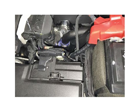
8. Install the 7.5 amp fuse that was previously removed into the fuse tap of the marker light wiring harness (P/N: 1115-15N515). Reinstall the fuse tap into the same location from which the fuse was originally removed. Trim the fuse box to allow clearance for the fuse tap lead and route the fuse tap lead through the trimmed area as shown.
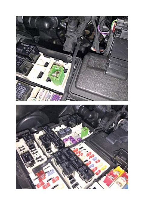
9. Reinstall the fuse box cover and positive terminal cover while making sure to not pinch any of the wiring.
10. Route the wire harness (1115-HWKWHN) along the front core support and secure with the provided zip ties (P/N: CTUV740) as shown.
11. Securely fasten the three (3) sets of connectors for auxiliary grille lighting and ensure that none of the wiring will be pinched when re-installing the front end components. NOTE: If desired, these connectors can be used to install additional 12-volt lighting. However, Roush Performance is not responsible for any problems that may occur as a result of improper installation of any auxiliary lighting that is not supported by Roush Performance.
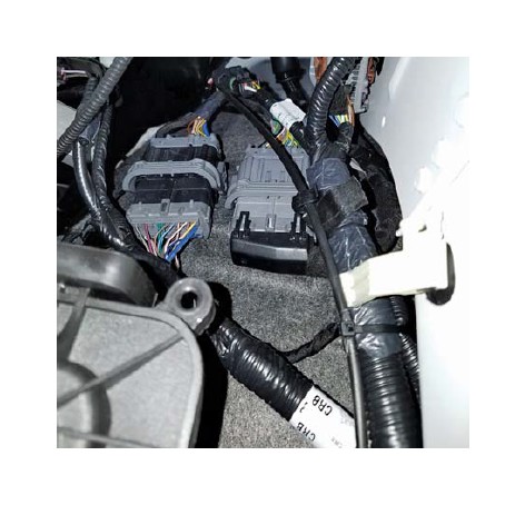
12. Route the marker light wiring harness (P/N: 1115- 15N515) along the driver side inner fender well and secure as shown. Make sure to connect both sections of the marker light harness together.
13. Reinstall the headlight, grille and radiator close out panel by following the reverse of steps 6 through 9 in the Disassembly section.
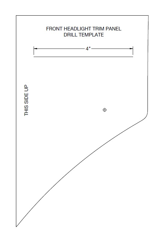
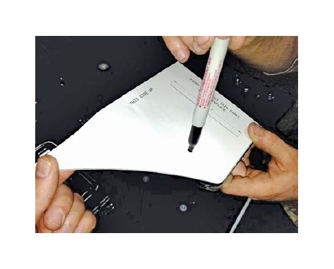
14. Use the supplied template on the last pages of the manual marked “FRONT HEADLIGHT TRIM PANEL DRILL TEMPLATE” to mark and drill an 11/16" hole in each of the front headlight trim pieces. Place the trim piece back on the vehicle to mark and drill an 11/16" hole in each of the large plastic brackets below the headlights.
15. Route each set of front marker light connectors through the holes that were drilled in the previous step and reinstall the headlight trim pieces.
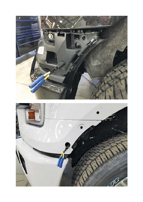
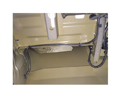
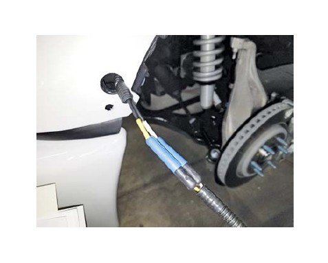
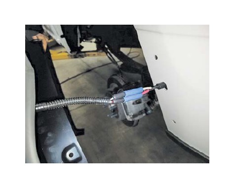
16. Continue routing the harness down along the driver side frame rail and secure with the provided zip ties (P/N: CTUV740) and edge clips (P/N: 156-00865) as shown.
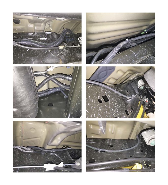
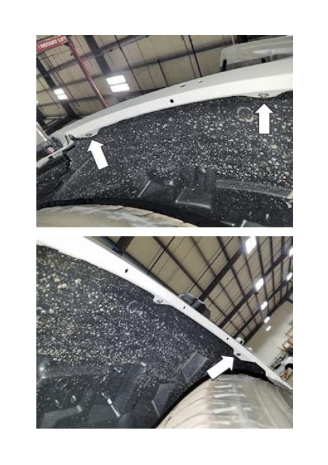
17. At the rear of the vehicle, secure the wiring harness using the provided edge clips (P/N: 156-00865).
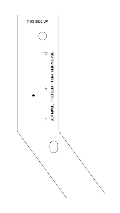
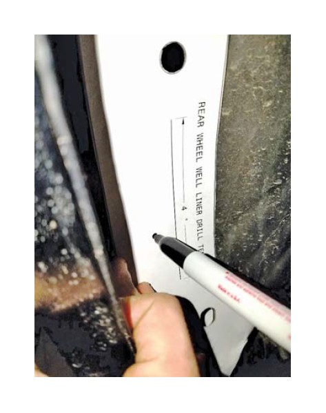
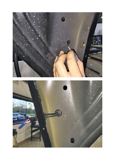
18. Use the supplied template on the last pages of the manual marked “REAR WHEEL WELL LINER DRILL TEMPLATE” to mark and drill an 11/16" hole in each of the rear wheel liners.
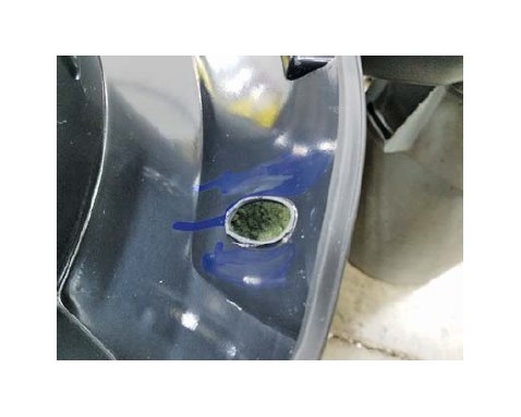
19. Seal the bare metal edge of the drilled holes with high quality automotive clear coat. Once dry, install the provided rubber grommets (P/N: 3MPN1) onto the wire harness pigtails and route them through each wheel well and fender. NOTE: If the vehicle was not equipped with factory wheel lip moldings, an additional 11/16" hole will need to be drilled through the fender lip to allow for the wiring harness to pass through. Install the grommets (P/N: 3MPN1) into each of the drilled holes.
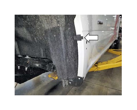
20. Secure the wire harness as shown with the edge clips (P/N: 156-00865).
FENDER FLARE INSTALLATION
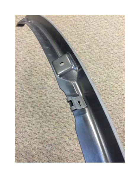
1. Install three (3) short U-clips onto each of the front fender fl are inner retaining brackets.
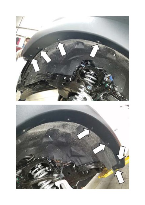
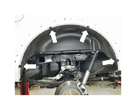
2. Remove three (3) screws with a 5.5 mm socket from each of the front inner wheel wells as shown.
3. Install one (1) front fender fl are inner retaining bracket on each side of the vehicle using the three (3) screws that were removed in the previous step. Torque to 0.9-1.1 Nm.
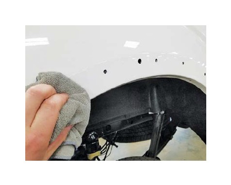
4. Clean each wheel well lip with isopropyl alcohol and a terry cloth.
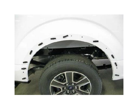
5. Set the front fender fl ares in place to mark the locations for the mylar pads. Apply one (1) mylar pad in the locations shown below and fold them around the lip of the wheel wells. Install one (1) J-clip around each of the mylar tabs.
6. Set each of the front fender fl ares in place on the vehicle while connecting the wiring harness for each marker light. Loosely install four (4) #2 Philips head screws as shown. NOTE: Before tightening the screws, make sure the rubber edge seal is fully seated and not rolled under the fl are.
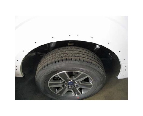
7. Push up and in on each fl are to preload them and torque the previously installed screws to 0.9-1.1 Nm. Install two (2) screws with a 7 mm socket that were previously removed in step 2. Install two (2) screws with a 5.5 mm socket that were previously removed in step 1. Torque to 0.9-1.1 Nm.
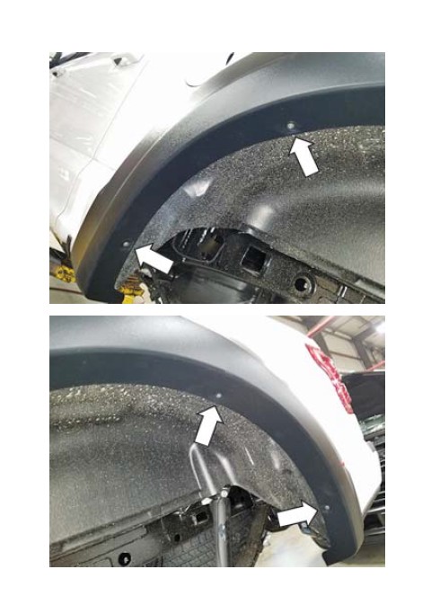
8. Set the rear fender fl ares in place to mark the locations for the mylar pads. Apply one (1) mylar pad in each of the locations shown below and fold them around the lip of the wheel wells. Install one (1) J-clip around each of the mylar tabs.
9. Set each of the rear fender fl ares in place on the vehicle while connecting the wiring harness for each marker light. Loosely install four (4) #2 Philips head screws as shown. NOTE: Before tightening the screws, make sure the rubber edge seal is fully seated and not rolled under the fl are.
10. Push up and in on each fl are to preload them and torque the previously installed screws to 0.9-1.1 Nm.
11. Install two (2) screws with a 10 mm socket that were previously removed in step 10. Torque to 0.9-1.1 Nm. NOTE: If the vehicle was not equipped with factory wheel lip moldings, these holes will need to be marked and drilled to utilize the No Wheel Lip Molding Hardware Kit (P/N: 1115-HWKWLM). Drill the holes to 1/4" then install the M6 J-clips (P/N: N523332) and bolts (P/N: R18020009-00).
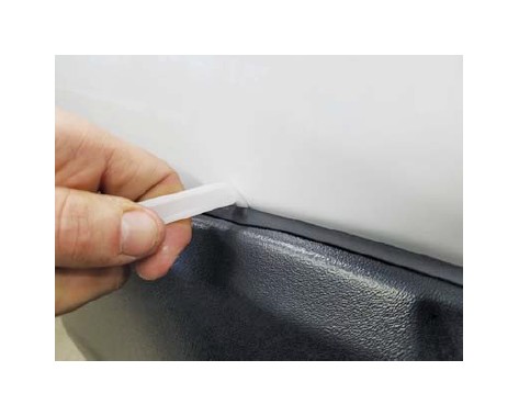
12. Use the supplied nylon trim tool and carefully slide it along the edge seals to ensure that they are fully seated.
Congratulations, the installation is complete!