FREE 1 to 3-Day Delivery on Orders $149+ Details
How to Install Roush by Fox 2.0 Suspension Kit (15-18 All, Excluding Raptor) on your Ford F-150
Tools Required
- Jack Stands or Hydraulic Lift
- Impact Driver
- 21 mm Socket
- Isopropyl Alcohol
- Floor Jack
- 19 mm Socket
- 18 mm Socket
- Pry Bar
- Ball Joint Puller
- Air Hammer
- Torque Wrench
- 8 mm Socket
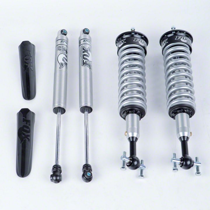
Shop Parts in this Guide
DISASSEMBLY
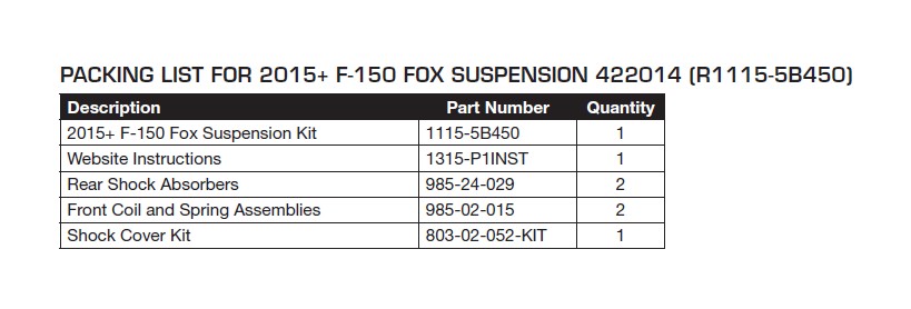
The following manual will guide you through the installation of the 2015 F-150 Fox Suspension Kit (P/N: R1115-5B450).
1. Begin by jacking up the vehicle and removing the wheels as described in the owner’s manual.
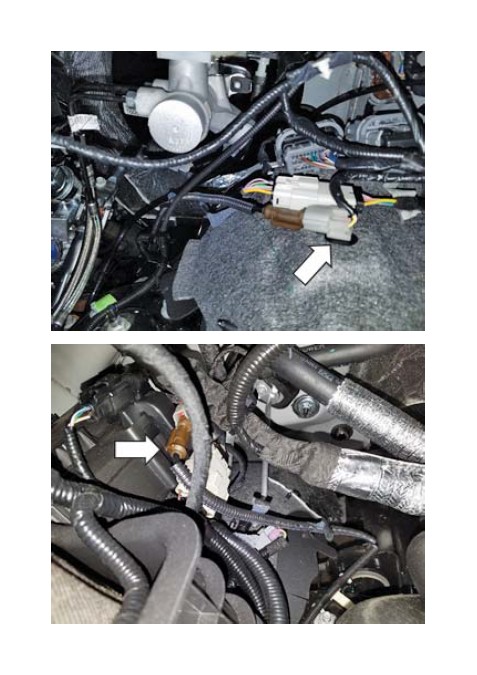
2. Disconnect the wheel speed sensor electrical connectors. The driver side connector is located on top of the inner wheel liner while the passenger side connector is located on the side of the fuse box.
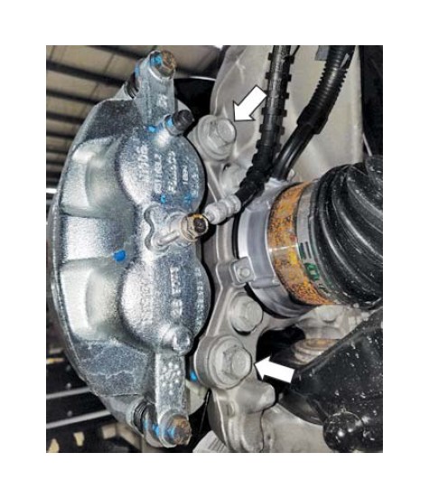
3. Remove and discard the two (2) anchor plate bolts from each brake caliper assembly. Set the brake caliper assemblies aside and remove each brake rotor.
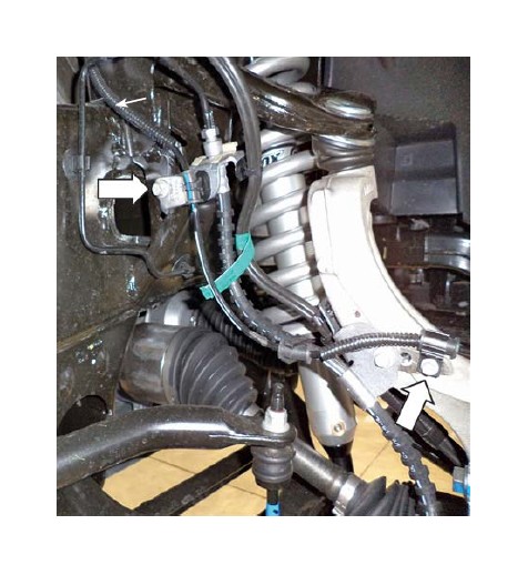
4. Remove the fasteners that retain the front wheel speed sensor brackets and then unclip the front wheel sensor wires from the retainers.
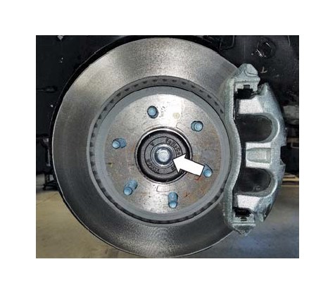
5. Remove and discard the wheel hub nut dust cap and the wheel hub nut.
Do not use a hammer to separate the outer tie rod from the spindle or damage may occur. Use the correct Ford separator tool, if necessary.
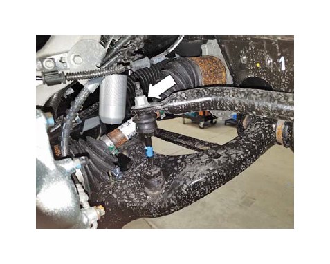
6. Remove and discard the nut from each outer tie rod. If necessary, use the Ford separator tool to remove the tie rod end from the spindle.
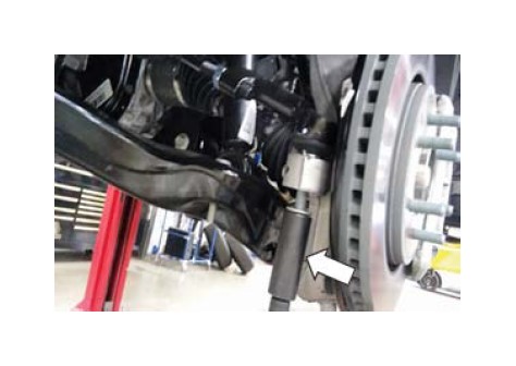
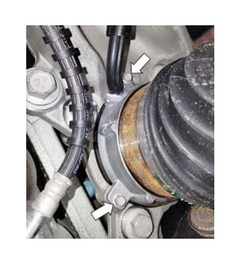
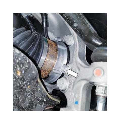
7. Remove the three (3) fasteners retaining the integrated wheel end (IWE) actuator at the end of each front axle.
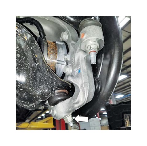
8. Remove and discard the nut from each upper ball joint. If necessary, use the Ford separator tool to remove the ball joint from the spindle.
9. Remove and discard the nuts from each lower ball joint using a _mm socket and remove each spindle. If necessary, use the Ford separator tool.
10. Remove and discard the upper nuts from each front stabilizer bar link.
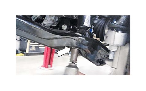
11. Remove and discard the two (2) lower shock absorber and spring assembly nuts from each lower control arm.
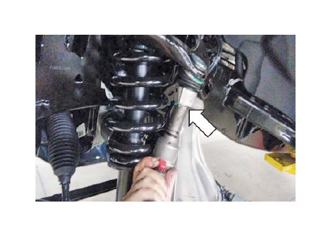
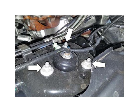
12. Remove and discard the three (3) upper shock absorber and spring assembly nuts from each shock tower. Remove each shock absorber and spring assembly.
13. Place a jack stand under each side of the rear axle to support it while removing the rear shock absorbers.
NOTE: A J-nut is used on the upper LH mount.
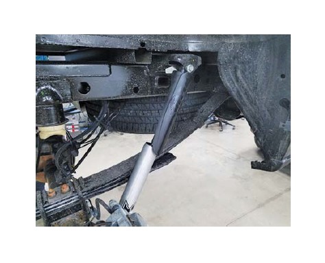
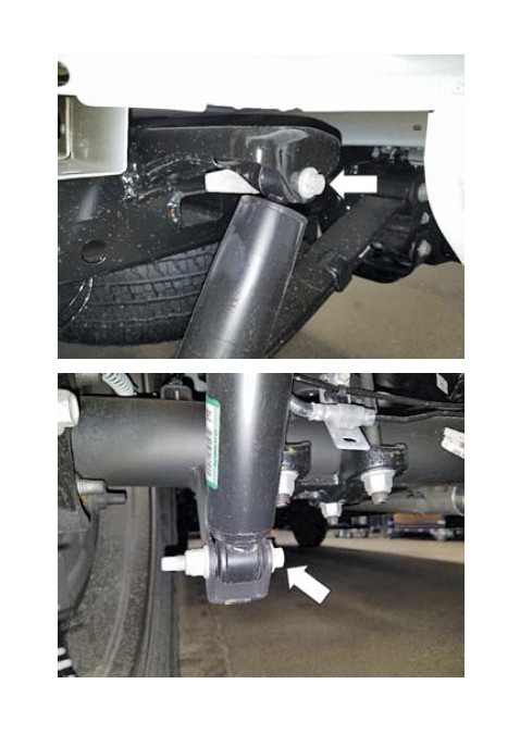
14. Remove and discard the upper and lower bolts and nuts for the rear shock absorbers.
ASSEMBLY
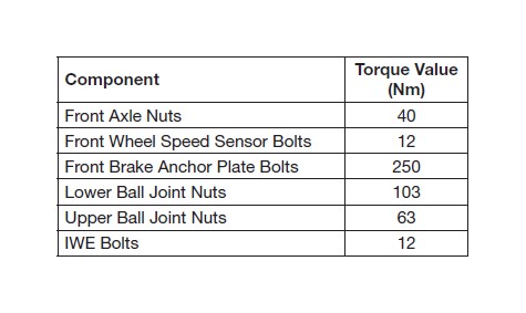
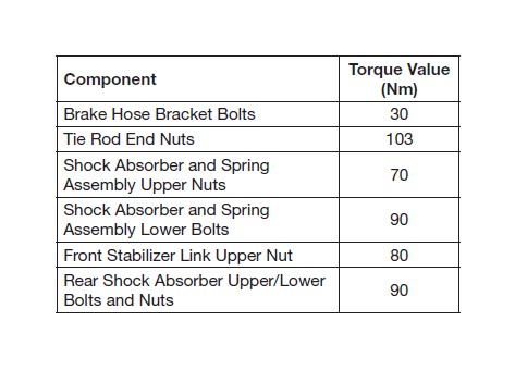
Follow the reverse of the disassembly process to reinstall the 2015 F-150 Fox Suspension Kit while referencing the torque chart shown and utilizing new hardware in the steps that required discarding of the take-off hardware.
NOTE: While reinstalling each front axle into the spindles, hold the constant velocity joint outward to maintain proper spline engagement with the IWE actuator gear.
1. Utilizing a hand pump, apply 24 in-Hg of vacuum to the IWE actuator through the large port.
2. Measure the distance between the threaded ends of each CV shaft to the inner bearing race. The minimum allowable distance is 15.5 mm. If the distance is less than that, rotate the CV shaft to allow for proper engagement of the IWE and CV splines.
Installation and torquing of the axle nut without proper engagement will result in damage.
NOTE: Install the new axle nut with vacuum still applied to the IWE.
3. Install the rear shock dust covers (P/N: 803-02- 052-KIT) as shown below.