 FREE 1 to 3-Day Delivery on Orders $149+ Details
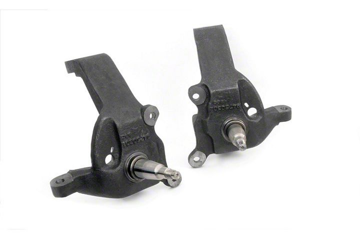
How to Install Rough Country 3 in. Lifted Spindles on your Ford F-150
Installation Time
6 hours
Tools Required
- 13MM Wrench
- 1/2” Ratchet
- Flat Punch
- Bearing Grease
- Floor Jack
- 21MM Deep Well Socket
- Hammer
- Pliers
- 1” Socket
- 2 Jack Stands
- Drivers and Passengers Spindles
- 2-Spindle cotter keys
- 4-Ball Joint cotter keys
- 2-Tie Rod Cotter Keys
- 4-Zip Ties
Shop Parts in this Guide
Thank you for choosing Rough Country for your suspension needs.
Rough Country recommends a certified technician install this system. In addition to these instructions, professional knowledge of disassemble/reassembly procedures as well as post installation checks must be known. Attempts to install
this system without this knowledge and expertise may jeopardize the integrity and/or operating safety of the vehicle.
Please read instructions before beginning installation. Check the kit hardware against the kit contents list. Be sure you have all needed parts and know where they go, separating parts according to where they go and placing hardware with
the brackets before you begin with save on installation time. If you are missing any components, are unsure where they go, or have a question about the installation please call Rough Country at 800-222-7023.

INSTALLATION INSTRUCTIONS
1. Jack up the front of the truck and support the frame rails with jack stands. The tool list is on the back page. NEVER WORK UNDER ANUNSUPPORTED VEHICLE.
2. Starting on the passenger side of the truck remove the front tire.
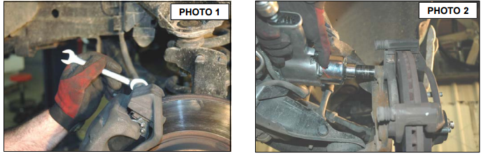
3. Remove the brake calipers from the spindle bracket using a 13 mm wrench as shown in Photo 1. Zip tie the caliper
to the frame rail. Do not let the caliper hang from the hose. Remove the two bolts securing the bracket from the
spindle using an 18mm socket. See Photo 2. Retain hardware for reuse.
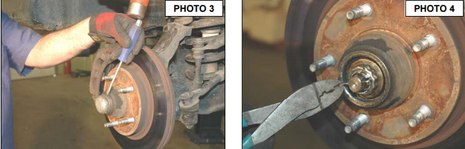
4. Remove the dust cap from the brake rotor using a flat head screwdriver. You will be reusing the dust cap later so do
not puncture it. See Photo 3.
5. Using pliers remove the cotter key from the spindle shaft. See Photo 4. Using a 1”socket remove the spindle nut
and washer. Retain hardware for reuse.
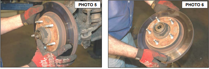
6. Slide the rotor off the spindle shaft. Make sure to keep the bearings inside the rotor. See Photo 5 & 6.
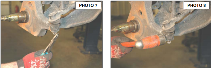
7. Using pliers remove the cotter pin from the tie rod. See Photo 7.
8. Using a 21mm socket remove the castle nut. Using a hammer hit the spindle only as shown in Photo 8 until the tie
rod pops out. Do not strike the tie rod itself or the threaded shaft. Retain the hardware for reuse.
9. If your vehicle has an anti-lock brake system, remove the sensor from the spindle. This will be reinstalled on the
new spindle.
10. Support the lower control arm with a jack. Raise the lower control arm 1”. This should be enough to relieve the tension
on the shock.
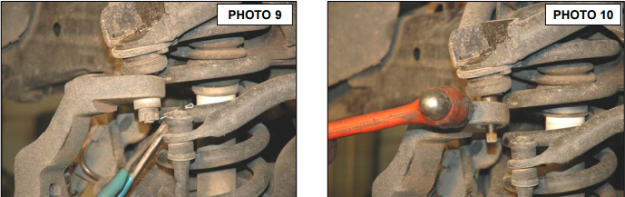
11. Using pliers remove the cotter pin from the upper ball joint. See Photo 9.
12. Using the 21 MM wrench loosen castle nut. Using a hammer hit the spindle as shown in Photo 10 until the upper
ball joint pops out. Do not strike the ball joint itself or the threaded shaft.
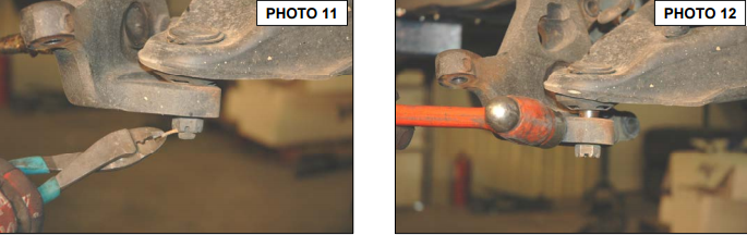
13. Using pliers remove the cotter pin from the lower ball joint. See Photo 11.
14. Using the 24mm socket loosen the castle nut. Using the hammer hit the spindle as shown in Photo 12 until the ball
joint breaks free. Do not strike the ball joint itself or the threaded shaft. Remove the upper and lower castle nut and
place spindle aside. Retain hardware for reuse.
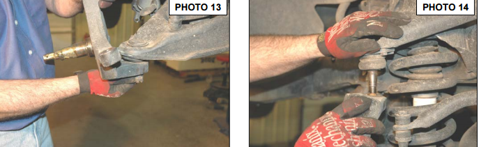
15. Install the new lifted passenger side spindle on the upper and lower ball joints using the stock castle nuts. Torque to
factory specs. See Photo 13 & 14.
16. Install the new cotter pins provided.
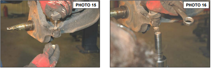
17. Install the tie rod using the castle nut and torque to factory specs. See Photo 15 & 16.
18. Install the cotter pin provided.
19. If your vehicle has ABS install the sensor at this time on the new spindle.
20. Using High Temp grease apply a light coating on the new spindle. Inspect your wheel bearings. If they are worn or
discolored replace them at this time.
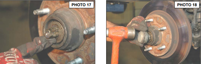
21. Slide the rotor with bearings on the spindle shaft. See Photo 17.
22. Install the spindle nut washer and nut. Tighten to factory specs. Do not over tighten.
23. Install the cotter pin provided. Using a hammer lightly tap the stock dust cap into place. See Photo 18.
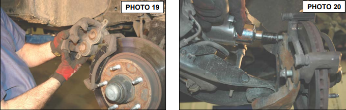
24. Install the caliper bracket on the spindle. See Photo 19.
25. Install the brake pads and the brake caliper reusing factory bolts. See Photo 20. Torque to factory specs.
26. Install the tire / wheel and torque to factory specs.
27. If shock absorbers were purchased, install at this time with factory hardware.
28. Repeat on drivers side.
29. Jack up front of the truck, remove the jack stands and lower the truck on the ground. Cycle the steering right to left
lock to lock checking for clearance of all components.
30. Vehicle will need to be aligned.
REAR BLOCK INSTALLATION (IF PURCHASED)
1. Support rear of vehicle with jack stands under the frame rail.
2. Remove the factory u-bolts.
3. With a floor jack, raise rear of vehicle until spring has cleared spring pad enough to install spacer blocks. In the case
of the vehicle having a factory block with a bump stop included on the block, and if the factory block is reused;
the new block will install on the bottom of the factory block.
4. Install new spacer blocks on spring pad aligning pin with hole in spring pad. (Short side of block goes towards front
of vehicle, if block has taper).
5. Lower vehicle slowly until spring contacts spacer blocks insuring that pin on bottom of spring aligns with center hole
in spacer block.
6. Install new u-bolts and hardware. Tighten u-bolts, alternating from bolt to bolt to 87 ft. /lbs
7. Lower vehicle and install shocks ,if purchased, with factory hardware.
POST INSTALLATION INSTRUCTIONS
1. Lug nuts should be check after 50 miles and all nuts and bolts should be checked and tightened after 500 miles. All
parts should be checked every 3000 miles for the life of the vehicle.
2. Recheck brake hoses and lines for proper clearances.
3. Perform steering sweep to check for appropriate tire clearance. Note- Some oversized tires may require trimming of
the bumper and valance
4. If new tires are installed that are more than 10% taller than original tires, the speedometer must be recalibrated for
the anti-lock brake system (if applicable) to function properly. Contact an authorized Ford dealer for details on recalibration.
5. Adjust headlights back to proper settings.
6. Have a qualified alignment center realign front end to factory specs.
7. Install “Warning to Driver” decal on sun visor.

