FREE 1 to 3-Day Delivery on Orders $149+ Details
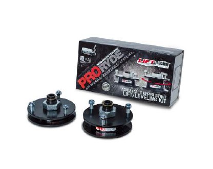
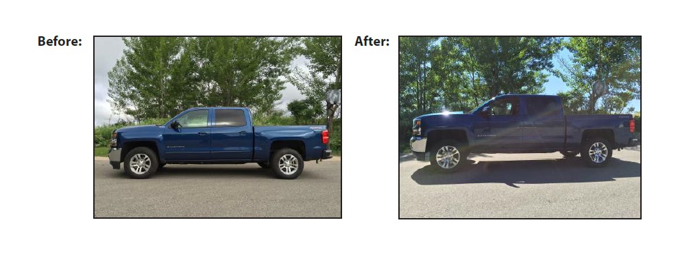
How to Install ProRYDE 2.25 in. to 3 in. Adjustable Front Leveling Kit (14-17 2WD/4WD Silverado 1500) on your Chevy Silverado
Bill of Materials
(1) Installation Instructions & Warnings
(2) 3-Piece Patented Upper Strut Kits
(6) M10-1.5 Nylock Nuts
(2) 1-1/4”-12 Large Adjustment Locking Jam Nuts
(2) 1-1/8” Snap Rings
(2) Tear-Resistant Nylon Bearings
ALWAYS WEAR PROPER EYE PROTECTION & USE TOOLS SPECIFIC TO THE JOB!
THIS PRODUCT HAS BEEN FACTORY PRE-TREATED WITH MARINE GRADE ANTI-SIEZE COMPOUND. NO LUBRICATION OF THE LARGE ADJUSTER THREAD IS NECESSARY PRIOR TO INSTALLATION.
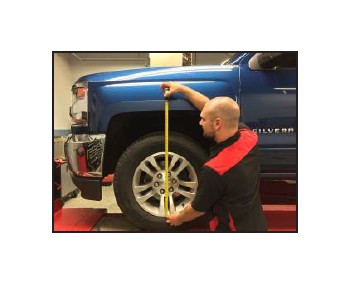
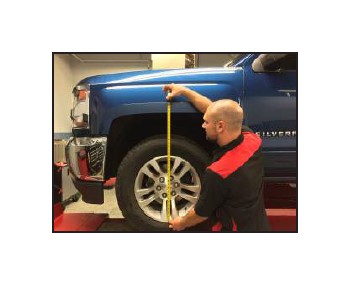
STEP 1: On a flat, level surface, MEASURE pre-installation ride height, FRONT & REAR, and write down measurements.
Front (L) __________________
Front (R)__________________
Rear (L)__________________
Rear (R)__________________
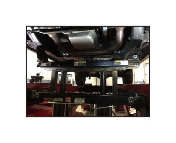
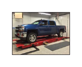
STEP 2: Position vehicle on a stable, flat surface or automotive lift. Suspend front wheels, lift-ing by the frame. Secure with jack stands & wheel chocks. Be sure engine is turned OFF and vehicle is in PARK.
STEP 3: Remove front wheels. Support lower control arm & spindle assemblies with jack or jack stand.
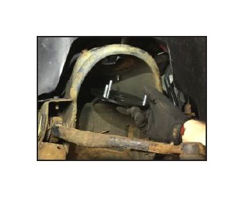
STEP 4: Disconnect ABS/ vacuum line brackets from upper control arm to allow slack.
STEP 5: Disconnect sway bar links at the lower control arm.
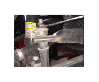
STEP 6: Loosen, but don't completely remove, upper ball joint & outer tie rod nuts. Leave both nuts finger tight.
***BE SURE BRAKE LINES HAVE ADEQUATE SLACK, AND TO PROPERLY SUPPORT BRAKE & SPINDLE ASSEMBLY!***
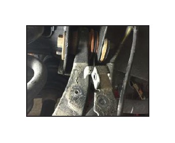
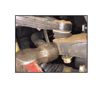
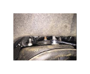
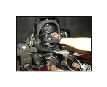
STEP 7: With stud nuts still installed, separate upper ball joints & outer tie rods from their tapers, using a hammer as shown.
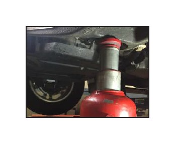
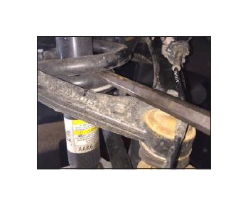
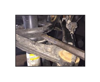
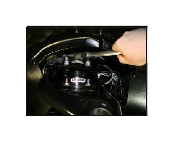
STEP 8: Using a pry bar put pressure on upper control arm by inserting pry bar end under spring. Push down and remove ball joint nut. SLOWLY release pressure on pry bar until upper control arm is free.
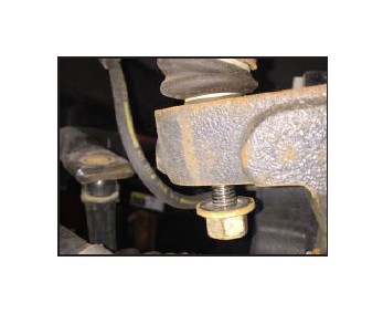
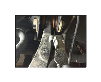
STEP 9: Disconnect & remove lower strut mounting bolts.
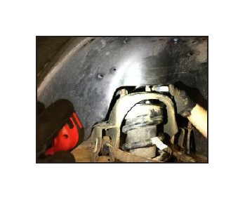
STEP 10: Supporting the strut assembly, remove the three upper strut mounting fasteners.
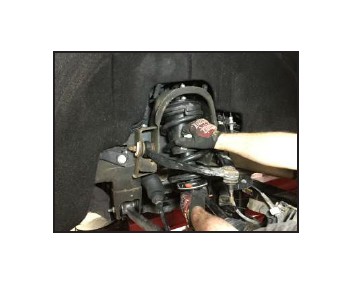
STEP 11: The Strut/Spring assembly is heavy and can cause injury to technician or damage to other componets if released too quickly. Remove the OE strut assembly.
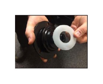
STEP 12: Install supplied tear-resistant Nylon Bearing to top of each Inner Adjustment Screw.
STEP 13: *IMPORTANT* Make sure Lift Machine turns freely before tightening nuts.
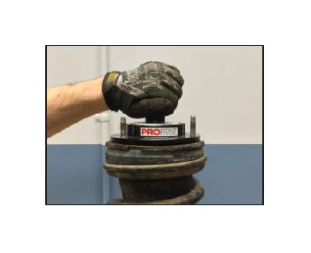
STEP 14: Install new adjustable Lift Machine spacer to upper strut & tighten using supplied Nylock nuts.
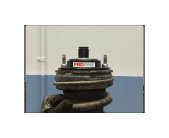
STEP 15: IMPORTANT! Be sure the Threaded Adjustment Screw Rotates FREELY after securing kit to the OEM strut. If not, slightly loosen the three upper stud nuts and reposition the Threaded Adjustment Screw slight UPWARD. Re-torque upper stud nuts to manufacturer's specifications and recheck that the Threaded Adjustment Screw now rotates properly for adjustment after installation.
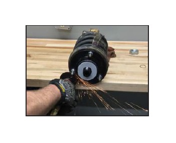
STEP 16: Trim OE studs flush with top of each Nylock nut.
STEP 17: Install the Top Connection Plate ONLY, with studs directed UPWARD into position in the strut tower, and secure with the OEM stud nuts. Torque stud nuts to OEM specifications.
STEP 18: Install strut assembly. The Threaded Inner Adjustment Screw should be threaded down in the most compact position for easiest reinstallation.
TIP: The use of a pry bar between the upper control arm and spring will help with install.
STEP 19: Install Large 1-1/4-12 Adjustment Locking Jam Nut included with this kit and tighten until snug to Top Connection Plate. Install Snap ring included with this kit.
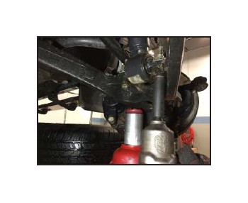
STEP 20: Install lower strut bolts and torque to manufacturer's specifications.
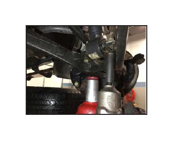
STEP 21: Install upper ball joint, outer tierod & sway bar nuts. TIP: Using a bottle jack may assist in reassembly of the ball joint to the knuckle. Torque to manufacturer's specifications.
STEP 22: Reconnect ABS/Vacuum line brackets that were disconnected in Step 4.
STEP 23: Reinstall tire/wheel assemblies, and check ALL suspension components and lug nuts have been properly torqued to manufacturer's specifications.
STEP 24: Lower the vehicle, jounce suspension and measure ride height of EACH SIDE of the vehicle. Measure from the bottom of the wheel/rim to the lip of the fender.
STEP 25: ADJUSTING FRONT RIDE HEIGHT AFTER INSTALLATION.
1) Lift vehicle by the frame, allowing wheels to hang freely. Secure using jack stands & wheel chocks.
2) Loosen the Large Adjustment Locking Jam Nut several complete turns.
3) Using a standard 1/2" ratchet or 24MM wrench, engage the Threaded Adjuster at the TOP of the new kit.
4) Turn COUNTER-CLOCKWISE to INCREASE ride height, and CLOCKWISE to DECREASE ride height.
5) Each full turn of the Threaded Adjuster will result in approximately 1/4" of ride height change.
6) Each 1/2 turn of the Threaded Adjuster will result in approximately 1/8" of ride height change.
IMPORTANT! RETIGHTEN THE LARGE 1-1/4"-12 TOP JAM NUT AFTER FINAL ADJUSTMENTS ARE MADE.
LOWER THE VEHICLE, JOUNCE SUSPENSION, AND MEASURE RIDE HEIGHT. BE SURE VEHICLE IS LEVEL FROM SIDE-TO-SIDE AND AT THE DESIRED RIDE HEIGHT, MAKING ADDITIONAL ADJUSTMENTS AS REQUIRED.
IMPORTANT! Check all fasteners for proper torque. Check to insure there is adequate clearance between all rotating, mobile, fixed and heated members. Check steering for interference and proper working order. Test brake system.
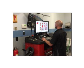
STEP 26: Perform a complete wheel alignment, utilizing a Certified Alignment Technician with experience working on lifted vehicles.
STEP 27: ADJUST HEADLIGHTS to accommodate new front ride height position
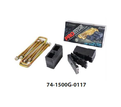
Complete a full 4-corner lift and install a PRORYDE SuperBLOK ADJUSTABLE rear Lift Kit!