 FREE 1 to 3-Day Delivery on Orders $149+ Details
How to Install PLX Exhaust Gas Temperature Sensor Module on your F-150
*Please read the instructions completely through at least once before proceeding with the installation to minimize errors.
*Double check polarity of power before powering it on for the first time.
Overview:
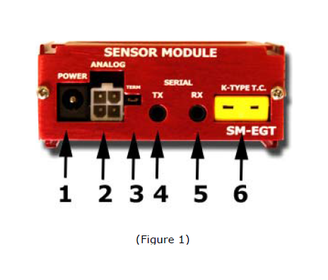
1. Connects to 12V-18V power source.
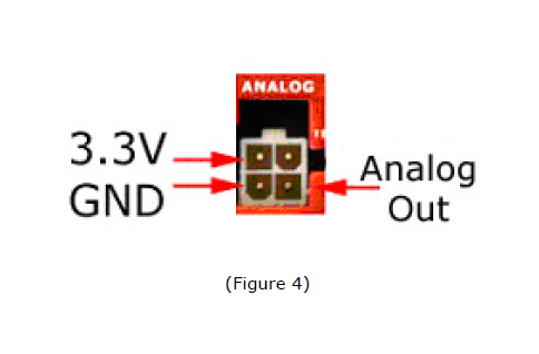
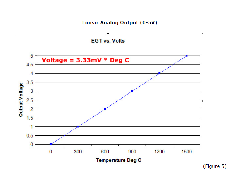
2. Analog outputs (0-5V linear output)
3. Termination jumper. Closed for first SM in iMFD daisy chain.
4. Connects to next SM in iMFD daisy chain or to first DM
5. Connects to previous SM or unconnected if first SM in iMFD daisy chain
6. Connects to K Type thermo coupler.
Install the Exhaust Gas Temperature Sensor:
1. Install the temperature probe on your header approximately 6-12 inches away from the engine block for best performance.
2. The PLX EGT K Type thermo coupler probe screws into a 1/8 NPT tap.
3. BE CAREFUL, DO NOT OVERTWIST the EGT probe’s wires during installation. This can cause the insulation to come loose and short the wires internally.
4. Mate the EGT probe with the SM-EGT module where indicated K-Type T.C.
Connecting Power to the Unit:
CAUTION! CONNECTING THE SM-EGT IN REVERSE POLARITY WILL DAMAGE THE UNIT! CHECK CONNECTIONS BEFORE POWERING ON.
1. The SM-EGT accepts 12-18V DC for power. Connect the negative wire (black) to your vehicle’s ground. This is usually the negative terminal of your automobile’s battery. Connect the positive wire (red) to your vehicle’s ignition power. This power is only supplied when your key is turned passed a specific position and is off when your key is removed. Your power connection must be capable of supplying at least 1 amp of current. A 5 Amp fuse is recommended for safety.
*If you plan to integrate the SM-EGT with other aftermarket devices by utilizing the analog output signal wire. Make sure that the negative wire (black) is connected as close as possible to your device's ground. This guarantees that both devices "see" the same reference ground and a more accurate interpretation of the output voltages will be achieved. Please refer to the PLXApp notes online for more information.
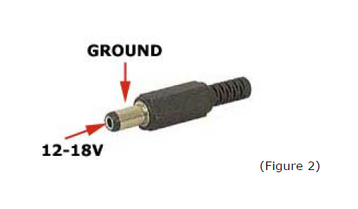
2. Locate the 2.1mm Power plug. Unscrew the plastic cover and insert it into the red/black power wires.
3. Solder or crimp the red power wire to the CENTER of the connector. (12-18V)
4. Solder or crimp the black power wire to the SHIELD of the connector. (GROUND)
Using the Sensor Module in the iMFD Chain:
1. If the SM-EGT is the only sensor module or last sensor module in the iMFD chain, be sure to have the termination jumper installed. Otherwise, remove the jumper. Please refer to (Figure 1) for the location of the termination jumper.
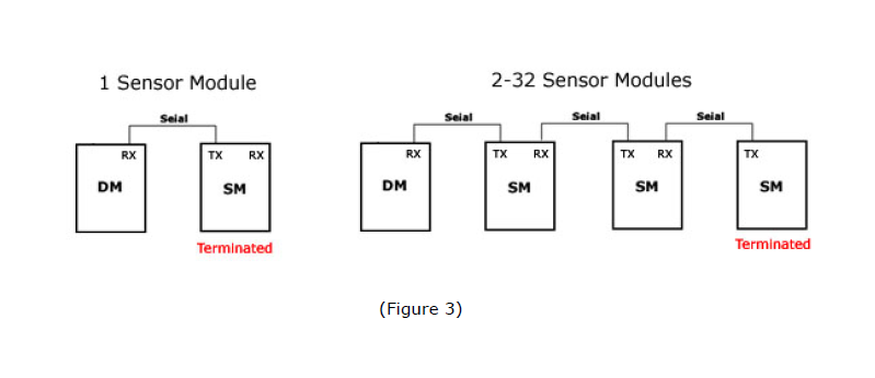
2. Connect the supplied 1ft serial cable according to the diagram below (Figure 3).
Using the Sensor Module Analog Output:
1. The SM-EGT has one 0-5V analog output designed to be interfaced with a number of aftermarket products such as engine management systems, data loggers and tuning electronics. It is not mandatory for you to use this output for your unit to properly function.
Recommended Accessory:
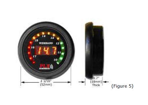
DM-5 EGT 52mm Gauge. Ideal for affordable EGT monitoring from your SM-EGT
Included Items:
1. SM-EGT main unit
2. 4ft red power wire
3. 4ft black ground wire
4. 4ft analog gray wire
5. Molex 4 pin white connector with 3 terminals
6. 2.1mm connector for power
7. 1ft Serial Cable
8. Termination jumper
9. Users guide
10. K-Type T.C (available separately)
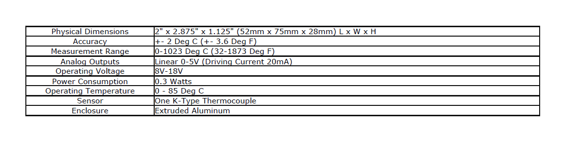
Specifications:
TERMS OF USE
PLX Devices Inc. does not guarantee the Sensor Module functionality with any ECU, data logger or other devices that uses the output signals. Implementation and integration of the Sensor Module with any other device(s) must be done at your own risk. Improper installation and usage may lead to engine damage. Mount and install the Sensor Module in a location where it does not obstruct the driver’s view and/or ability to safely control the vehicle.

