 FREE 1 to 3-Day Delivery on Orders $149+ Details
How to Install Firestone Heavy Duty Air Command Single-Path Air Control System - Analog Gauge
Tools Required
- 3/16" DRILL BIT
- 1/4" DRILL BIT
- WIRE CRIMPER/STRIPPER
- PHILLIPS SCREW DRIVER
- (2) 7/16" WRENCHES
- 3/8" DRILL BIT
- POWER DRILL
- PLIERS
- UTILITY KNIFE
- CENTER PUNCH
INSTALLATION INSTRUCTIONS
Congratulations on your purchase of a new Air Command kit. This kit was designed to provide inflation control of your air helper springs. This kit will be an asset to your vehicle, meeting nearly all of your air supply needs.
Please take a few minutes to read through the instructions, identify the components, and learn how to properly install your Air Command kit.
NOTE:
The Air Command kit can be used with all air helper spring products. If you are installing an air suspension system, do not install the air line tubing to the air springs as stated in the suspension system instruction manual. If you are adding the Air Command kit to an existing air suspension system, you will need to deflate the air springs and remove the air line tubing.
NOTE ON CONNECTING THE AIR LINE TUBING:
Cut the air line tubing as squarely as possible. To connect the air line tubing to the fittings, push the tubing into the fittings as far as possible. If for any reason the tubing must be removed, first release the air pressure from the air helper spring. Push the collar toward the body of the fitting and the pull out the tubing. To reassemble, make sure the tubing is cut squarely and push the tubing back into the fitting.
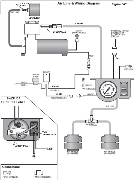
AIR LINE & WIRING DIAGRAM
STEP 1—SELECT A MOUNTING LOCATION FOR THE CONTROL PANEL
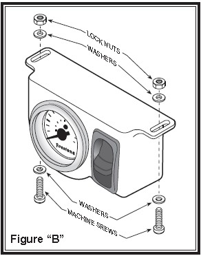
Select a mounting surface under the dashboard or other protected location. Using the control panel as a template, mark each of the mounting points with a center punch. Drill a 3/16" diameter hole on each center mark see Figure “B”. Do not attach the control panel at this time.
STEP 2—PREPARE THE COMPRESSOR
Install the push-to-connect male fitting into the check valve on the compressor head see Figure "A". Tighten the fitting sufficiently to engage at least two threads with pre-applied orange thread sealant. DO NOT OVERTIGHTEN THE FITTING.
STEP 3—MOUNT THE COMPRESSOR
Begin by removing the negative battery cable. Select a convenient location to mount the compressor. This location should provide ample air flow and be protected from airborne debris and moisture. The mounting surface should be rigid to support the compressor, such as under the hood on a fender well or in a vented storage compartment. The compressor is oil-less and can be mounted in any orientation necessary for installation.
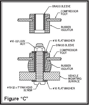
Using the compressor as a template and a center punch, mark and drill four 3/16" holes. Any burrs in the holes should be removed to prevent damage to the rubber isolators. Mount the compressor using the supplied 10 -32 x 1" machine screws, 10 -32 lock nuts, and 3/16" washers see Figure “C”. Maximum vibration isolation can be achieved by properly mounting the compressor. The machine screw and nut should be tightened only enough to bottom-out the brass insert see Figure “C”. DO NOT OVERTIGHTEN. Overtightening will crush the brass insert and the rubber isolator, thereby reducing vibration isolation. Finally, connect the black wire with the ring terminal from the compressor to a suitable ground.
STEP 4—ROUTE THE AIR LINE
Before installing the air line tubing, ensure that there is no pressure in the air springs. To release the air pressure, remove the valve core from the manual inflation valves or release the pressure by using a tire gauge to depress the valve stem.
A) COMPRESSOR TO CONTROL PANEL
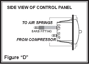
Cut a piece of air line tubing that will reach from the control panel to the compressor. Cut the air line tubing as squarely as possible and install the tubing on to the barbed fitting on the back of the switch marked SUP (supply) see Figures “A” & “D”. Before attaching the air line tubing to the control panel, soak the end (1") of the air line in hot water for a few minutes to soften the tubing. Do not use pliers to work the tubing on to the barbed fitting, as the tubing may be damaged. It may be necessary to drill a hole in the firewall to route the tubing. Do not fold or kink the tubing. Ensure that the tubing is protected from sharp edges when passing through the firewall.
B) CONTROL PANEL TO AIR SPRINGS
Cut a length of air line tubing that will reach from the control panel to the rear of the vehicle. Slide the tubing as far as possible onto the barbed fitting on the back of the gauge, see Figures “A” & “D”. Do not use pliers to work the tubing on to the barbed fitting, as the tubing may be damaged. Install a T-fitting on the opposite end of the tubing at the rear of the vehicle. Route a length of air line tubing from the T-fitting to each air spring. Use the suppled nylon ties to secure the tubing to the vehicle. Make sure that the tubing is protected from sharp edges when passing through the firewall.
STEP 6—ATTACH THE CONTROL PANEL TO THE DASHBOARD
Place the air control panel on the dash where the holes were drilled in Step 1. Using the provided machine screws, lock nuts, and washers attach the air control panel to the dashboard or selected mounting surface see Figure “B”.
STEP 7—ROUTE THE ELECTRICAL WIRE
Install the relay within three feet of the compressor. Nylon ties can be used to secure any excess wire and the relay neatly into place. Route the white wire labeled “Switch Panel” to the control panel. Connect the white wire to one of the white wires on the back of the switch. The remaining white wire will be grounded to the vehicle. Next, connect the orange wire labeled “Comp ” to the red (positive) wire on the compressor. Connect the red, fused wire labeled “Bat ” from the relay to the battery or another 12V (positive) source capable of supporting 20 amps. See Figure “A”.
STEP 8—WIRE THE CONTROL PANEL FOR ILLUMINATION
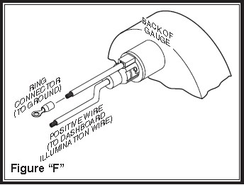
There are two wires on the back of the gauge; Connect the one wire to a fused dashboard illumination wire. Connect the other wire to a suitable ground source see Figure “F”.
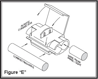
Attach the end of the positive wire to a dashboard illumination wire using a wire connector. Slip the wire connector over the existing dashboard illumination wire and insert the un-stripped gauge panel wire into the wire connector. Close the wire connector over the wires with pliers, see Figure “E”. Attach the other wire to a ground source by crimping a ring connector on to the wire and securing it to a suitable ground source on the vehicle. Note: Should additional wire be necessary to reach the dashboard illumination wire and ground source, use 16 gage multi-strand wire.
STEP 9—CHECK THE SYSTEM
With the Air Command kit and your air helper springs installed, you are ready to test the system. Reattach the negative battery cable. Turn on the vehicle’s ignition. Push the paddle switch up to inflate the air springs. The gauge will display how much air pressure is in the air springs. Inflate the air helper springs to 70 psi OR the max operating pressure for the air springs, whichever is less, and check the fittings for air leaks with an applied solution of soap and water. If a leak is detected at a tubing connection, check to make sure that the tube is cut as square as possible and that it is pushed completely into the fitting. The tubing can easily be removed from the fitting. First, release the pressure from the air spring. Push the collar towards the body of the fitting and pull out the tube.
NOTE: If it is necessary to remove the air line from one of the barbed fittings, use a shaving motion with a sharp knife to shave the air line until it is thin enough to pull off of the barbed fitting. DO NOT cut, scrape, or damage the fitting or it may cause a leak path.
NOTE: If the system inflates the air springs normally but only releases the air pressure in the line and not the air springs, the air lines are not properly installed on the switch and gauge. Switch the air lines making sure the line from the air spring is connected to the gauge, and the line from the compressor is connected to the "SUP" fitting on the switch.
SYSTEM OPERATION
The Air Command kit allows the air springs to be inflated from the inside of the vehicle. Push the paddle switch up to inflate the air springs and push the paddle switch down to deflate the air springs.

