FREE 1 to 3-Day Delivery on Orders $149+ Details
How to Install Fabtech 2 in. Uniball Upper Control Arm System w/ Dirt Logic Coilover Reservoirs & Shocks on your Silverado
Tools Required
- Basic Hand Tools
- Floor Jack
- Jack Stands
- Assorted Metric and S.A.E sockets, and Allen wrenches
- Torque Wrench

Shop Parts in this Guide
- Fabtech 2-Inch Uniball Upper Control Arm System with Dirt Logic Coil-Over Reservoirs and Shocks (07-13 2WD/4WD Silverado 1500 Extended Cab, Crew Cab)
- Fabtech 2-Inch Uniball Upper Control Arm System with Dirt Logic Coil-Over Reservoirs and Shocks (14-18 2WD/4WD Silverado 1500 Double Cab, Crew Cab)
- Fabtech 2-Inch Uniball Upper Control Arm System with Dirt Logic Coil-Overs and Shocks (07-13 2WD/4WD Silverado 1500)
- Fabtech 2-Inch Uniball Upper Control Arm System with Dirt Logic Coil-Overs and Shocks (14-18 2WD/4WD Silverado 1500 Double Cab, Crew Cab)
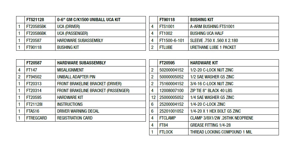
- PARTS LIST -
- PRE-INSTALLATION NOTES -
Read this before you begin installation-
Check all parts to the parts list above before beginning installation. If any parts are missing contact Fabtech at 909-597-7800 and a replacement part will be sent to you immediately.
Read all instructions thoroughly from start to finish before beginning the installation. If these instructions are not properly followed severe frame, driveline and / or suspension damage may occur.
Check your local city and state laws prior to the installation of this system for legality. Do not install if not legal in your area.
Prior to the installation of this suspension system perform a front end alignment and record. Do not install this system if the vehicle alignment is not within factory specifications. Check for frame and suspension damage prior to installation.
The installation of this suspension system should be performed by two professional mechanics.
Use the provided thread locking compound on all hardware.
WARNING- Installation of this system will alter the center of gravity of the vehicle and may increase roll over as compared to stock.
Vehicles that receive oversized tires should check ball joints, uniballs, tie rods ends, pitman arm and idler arm every 2500-5000 miles for wear and replace as needed.
Verify differential fluid is at manufactures recommended level prior to kit installation. Installation of the kit will reposition the differential and the fill plug hole may be in a different position. (For example, if the manufacture recommends 3 quarts of fluid, make sure the diff has 3 quarts of fluid). Check your specific manual for correct amount of fluid.
- INSTRUCTIONS -
FRONT SUSPENSION
1. Disconnect the negative terminal on the battery. Jack up the front end of the truck and support the frame rails with jack stands. NEVER WORK UNDER AN UNSUPPORTED VEHICLE! Remove the front tires.
2. Starting from the driver side remove the upper ball joint nut. Disconnect the upper ball joint from the knuckle by striking the knuckle with a large hammer next to the upper ball joint on the knuckle to dislodge the ball joints. Use care not to hit the ball joint when removing.
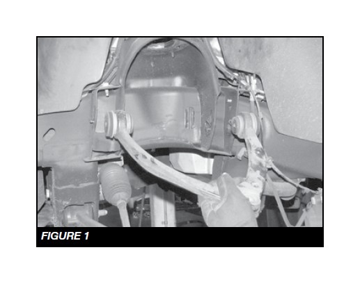
3. Mark the location of the alignment cams on the frame of the upper control arm pocket. Remove the upper control arm and retain the factory hardware. SEE FIGURE 1
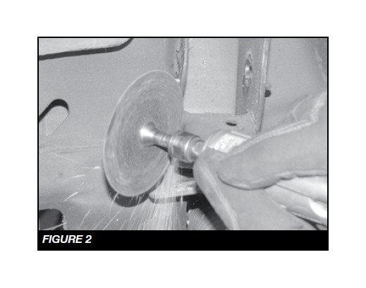
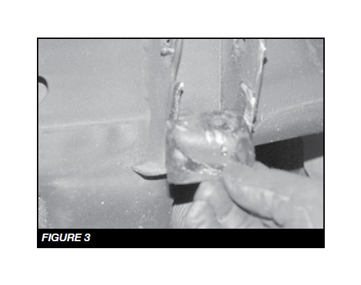
4. Using a die grinder, remove the factory droop stop from the control arm pocket. SEE FIGURES 2-3
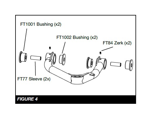
5. Locate the Fabtech driver’s side control arm FT20585BK, two FT1002 bushings, two FTS1001 bushings, two grease zerks FT84, and two sleeves FT1500-6-101.
6. Install all these components in the control arm barrels. SEE FIGURE 4
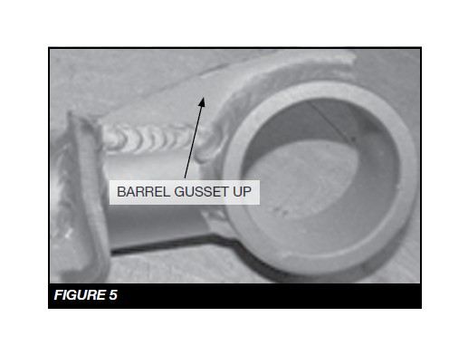
7. Install the new Fabtech upper control arm in the factory upper control arm pockets using the factory hardware at the previously marked alignment cam location. When installing the arm on the truck, make sure the barrel gussets are facing up. Torque to 100 ft-lbs. SEE FIGURE 5
8. Using a drill and a 1/2” bit. Chase out the factory knuckle where the original ball joint was attached.
9. Locate FT94502 Uniball adapter pin, and two FT147 uniball misalignment spacers.
SEE FIGURE 6 FOR STEPS 9 - 14
10. Insert the uniball pin into the factory knuckle upper ball joint taper. Install the 1/2 -20 lock nut with thread lock compound and flat washer onto the bottom side of the pin. This will lock the pin into the knuckle. Torque to 127 ft-lbs.
11. Install one FT147 uniball misalignment spacer on to the pin.
12. Swing the control arm down, slide the pin into the uniball on the control arm seating the lower FT147 spacer in the control arm.
13. Install the upper FT147 uniball misalignment spacer onto the pin.
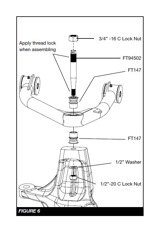
14. Install the 3/4” -16 lock nut on the top side of the pin with thread lock compound and torque to 150 ft-lbs.
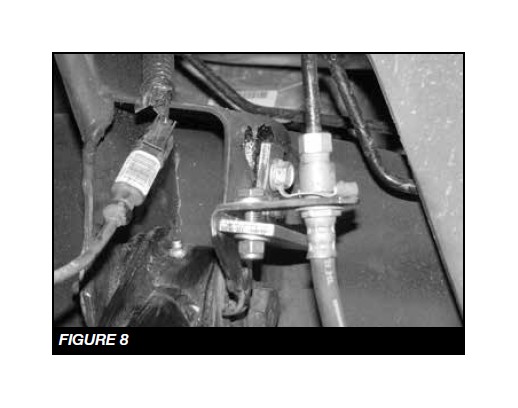
15. Locate Factory brakeline and wheel speed sensor.
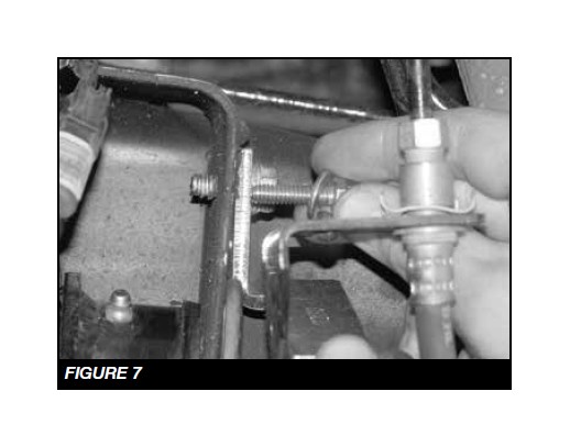
16. Install the brake line drop FT20313 using the ¼”-20 x 1” bolts, nuts and washers. Torque to 14 ft-lbs. SEE FIGURES 7-8
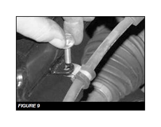
17. Attach the wheel speed sensor wire to the small tab on the control arm using the clamp, ¼”-20 x 1” bolts, nuts and washers. Torque to 14 ft-lbs. SEE FIGURE 9
18. Repeat 2-15 on the passenger side of the vehicle.
19. Install tires and wheels and torque lug nuts to wheel manufacturer’s specifications. Turn front tires left to right and check for appropriate tire clearance. Note - Some oversized tires may require trimming of the front bumper & valance.
20. Check front end alignment and set to factory specifications. Readjust headlights.
21. Recheck all bolts for proper torque.
22. Recheck brake hoses, ABS wires and suspension parts for proper tire clearance while turning tires fully left to right.
23. Check the fluid in the front and rear differential and fill if needed with factory specification differential oil. Note - some differentials may expel fluid after filling and driving. This can be normal in resetting the fluid level with the new position of the differential/s.
24. Install Driver Warning Decal. Complete product registration card and mail to Fabtech in order to receive future safety and technical bulletins on this suspension.
25. Have vehicle properly aligned to factory specs.
Vehicles that will receive oversized tires should check ball joints, uniballs and all steering components every 2500-5000 miles for wear and replace as required.
RETORQUE ALL NUTS, BOLTS AND LUGS AFTER 50 MILES AND PERIODICALLY THEREAFTER.