 FREE 1 to 3-Day Delivery on Orders $149+ Details
How to Install Edelbrock E-Force Stage 1 Street Supercharger Kit (04-08 2WD 5.4L) on your Ford F-150
Tools Required
- Jack and Jack Stands OR Service Lift
- Panel Puller
- Ratchet and Socket Set including 5.5mm (or 7/32”), 7mm, 8mm, 10mm, 12mm (deep), 13mm, 15mm & a 9/16” Spark Plug Socket
- 12” Ratchet Extension Bar
- 1/2” Breaker Bar
- Flat Blade & Philips Screwdrivers
- Torx-20 Driver
- 1/8” Allen Wrench
- 5/8” Fuel Line Removal Tool
- Torque Wrench
- Vice
- Needle Nose Pliers
- Pliers OR Hose Clamp Removal Tool
- Hacksaw, Drill & File OR Grinding & Cut-Off Wheels
- Impact Wrench
- 24mm Allen Tool (‘09 Mustangs only)
- Wire Stripper
- Wire Crimper
- Terminal Removal & De-Pinning Tools OR Safety Pin
- Heat Gun
- Blue Loctite
- O-ring Lube
- Anti-sieze
- Dielectric Grease
- Masking Tape

Shop Parts in this Guide

1. Use an 8mm socket to loosen the negative battery terminal clamp and remove it. Tuck it to the side to prevent any accidental contact with the negative battery terminal.
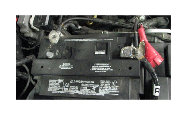
2. Use a 10mm socket to remove the nut on the positive battery terminal that retains the alternator power wire. Detach this wire from the terminal, then loosely reinstall the nut.
3. Use an 8mm socket to loosen and remove the positive battery terminal clamp, then tuck the wire over to the side.
4. Pull the plastic sleeve off of the battery, then use an 8mm socket and an extension bar to loosen the long bolt that secures the battery hold down wedge. Remove this wedge and set it to one side, then remove the battery.
5. Use an 13mm socket to remove the four bolts holding the battery tray in place. Remove and set aside the tray.

6. Use a philips head screwdriver to raise the head of the seven push-pins that retain the radiator shroud, then use a panel puller to fully remove the push-pins. Lift the shroud off the truck and set it and the push-pins aside.

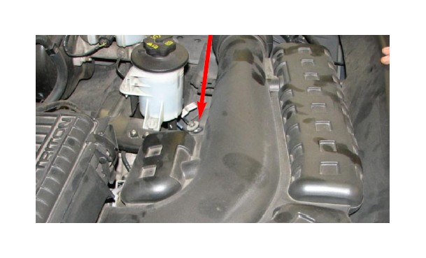
7. Remove the bolt that retains the air inlet resonator tube in place. Pull the air tube out out of the fender and airbox and discard it.
8. Detach the mass airflow sensor electrical connector from the airbox. Use a T20 Torx driver to remove the MAF sensor from the airbox and retain it for reuse later.

9. Disconnect the PCV tube running between the airbox and passenger side valve cover and discard it.
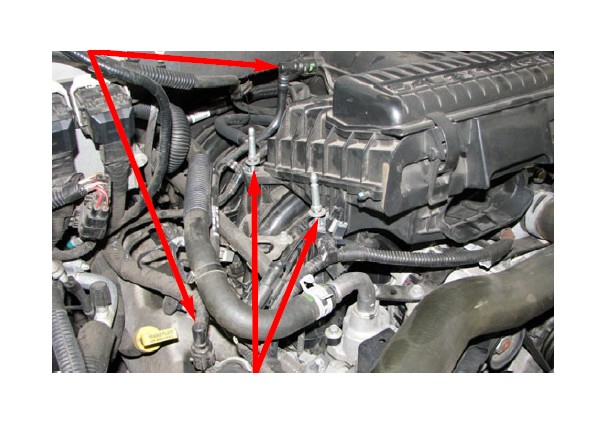
10. Use a 10mm socket to remove the four bolts that hold the airbox to the intake manifold. Lift and remove the airbox. The airbox and air filter can both be discarded.
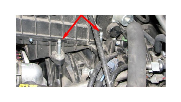
11. Use a 10mm socket to remove the four bolts that secure the throttle body.
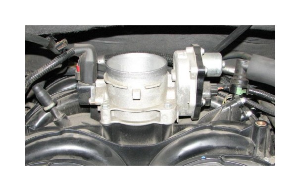
12. Detach the throttle position sensor (TPS) connector from the passenger side of the throttle body. Pull back the red tab on the electronic throttle control (ETC) connector and detach it. Remove the throttle body and set it aside for reuse later.
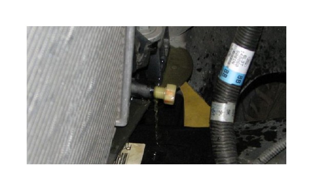
13. Place a tray below the passenger side frame rail to collect coolant as it drains, then loosen the petcock at the bottom of the radiator to drain the cooling system. Close the petcock once the cooling system has been drained.
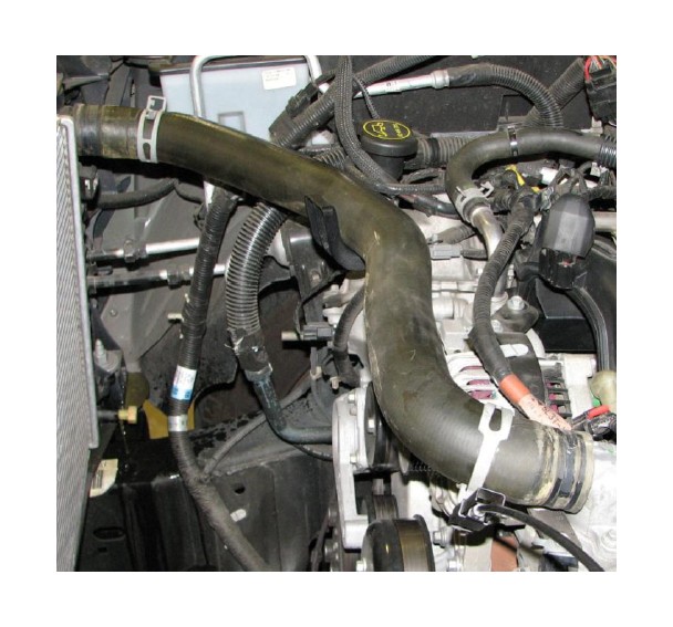
14. Use a pair of pliers or a clamp removal tool to remove the upper radiator hose.
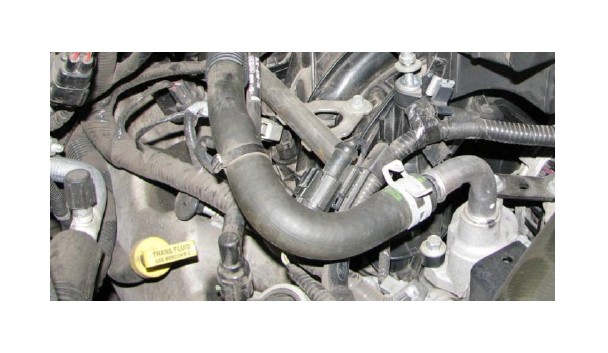
15. Use a pair of pliers or a clamp removal tool to remove the heater hose from the water crossover.
16. Use a 10mm socket to remove the nuts and bolts that retain the air inlet tube support bracket. The bracket and hardware can be discarded.
17. Use a fan clutch nut wrench and a fan pulley holding wrench to loosen the radiator fan. Do not attempt to fully remove the fan until the fan shroud has also been loosened.
18. Loosen and remove the two bolts retaining the fan shroud. Lift and remove the fan shroud and fan together and set them aside for reuse later.
19. Insert a 1/2” drive breaker bar into the square hole of the belt tensioner. Push the breaker bar towards the driver side fender and remove the serpentine belt.

20. Use a panel puller to seperate the wire harness from the alternator strap.
21. Use a 10mm socket to remove the four bolts that retain the upper alternator strap.
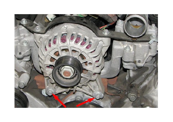
22. Support the alternator while using a 10mm socket to loosen the two bolts that support the alternator. Lift the alternator off these bolts and rotate it so that the power wire and electrical connector can be accessed. Remove and discard the two bolts.
23. Remove the electrical connector from the alternator. Use a 10mm socket to remove the nut retaining the power wire. Remove the power wire and replace the nut.
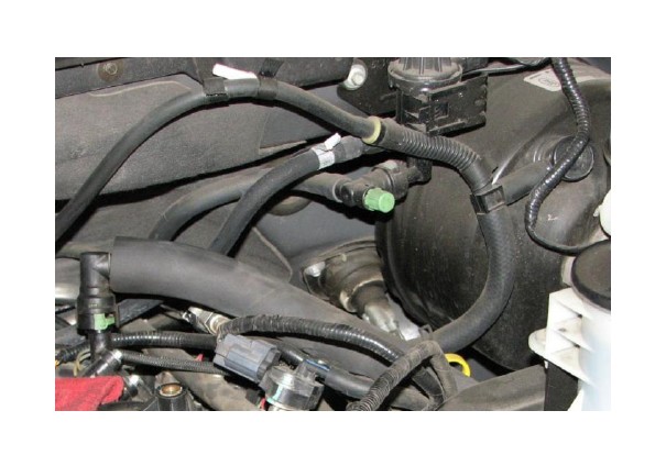
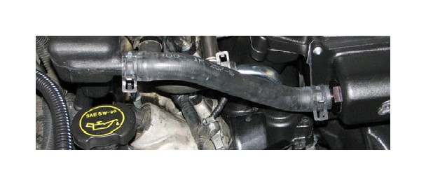
24. Disconnect the vacuum hose from the brake booster. Follow the hose back to where it connects to the rear of the intake manifold. Pull the nearby wire harness off its mounting stud then pull the vacuum hose off the nipple and remove it as a complete assembly. 2004 model year trucks should also remove the 4wd check valve hose.
25. Disconnect the electrical connector and vacuum hose from the fuel pressure sensor (FPS).

26. Push off the fuel line lock clip, then use a 5/8” fuel line removal tool to disconnect the fuel line from the fuel rail. Use a shop rag to absorb any excess fuel.
27. Disconnect the electrical connector from each of the fuel injectors.
28. Use an 8mm socket and a short extension bar to remove the four bolts retaining the fuel rail. Lift the injectors out of their provisions and remove the rails and injectors as a single assembly.
29. Drain as much of the fuel from the rails as possible, then use a shop rag to absorb the rest. Push the lock clips off each of the injectors and set them aside. Pull and twist the injectors to remove them from the rails.
30. Use a 10mm socket and a short extension bar to remove the ten intake manifold bolts.
31. Lift the intake manifold and pull it forward to access the charge motion control valve (CMCV) connector at the rear. Disconnect it and remove the manifold.
32. Use an 8mm socket to unbolt the thermostat housing and remove it. The housing, thermostat, bolt and o-ring will all be reused.
33. Use an 8mm socket to unbolt and remove the water crossover from the engine. Remove and retain the gaskets on each end.
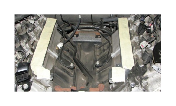
34. Use a soft cloth to clean any irregularities on the deck surface of the cylinder heads. Use two strips of masking tape to prevent any debris from entering the ports.
35. Set the supercharger assembly right side up on a workbench and lower the fuel rails onto the top of the blower manifold. Note that the rear crossover contacts the back of the manifold.
36. Place the fuel rails in a non-serrated vice and gently push the rails apart, test fitting frequently, until the fuel rail tabs line up with hold down bolt holes on the manifold. The rails only need to be spread slightly.
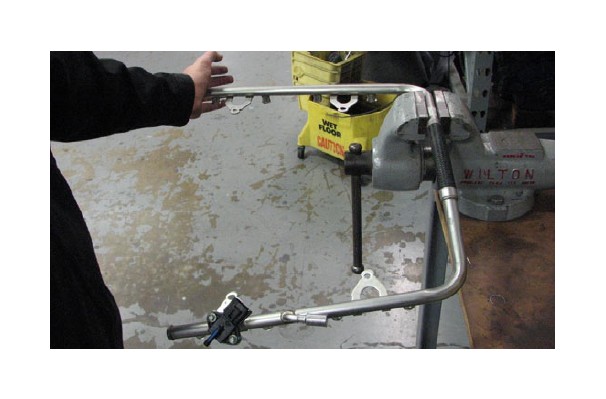
37. Snap the stock lock clips onto the supplied fuel injectors. Note that the grooves in the injectors are designed to accept the lock clips so that the injectors are properly oriented when installed on the rails.
38. Apply a small amount of o-ring lube to each of the supplied injectors then push them into the rails until the clips snap into place.
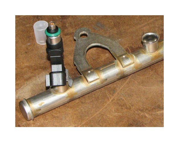
39. Use a 15mm wrench to remove the nut from the stud located at the top of the engine cover, on the driver side.
40. Use an 18mm wrench to remove the stud.
41. Install the M8 x 65mm bolt supplied in Bag #3 in the same location.
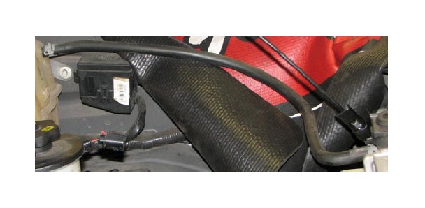
42. Mount the water pump relay on the firewall stud located near the passenger side fender. Route the ground strap to the bolt slightly above it and to the left.
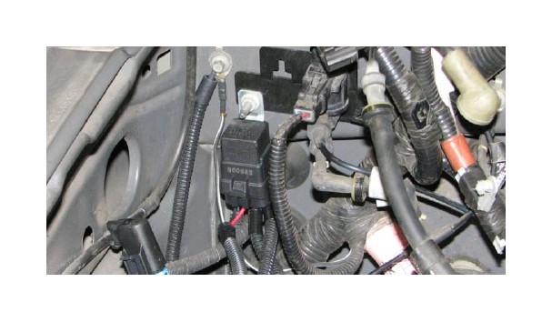
43. Mount the water pump fuse holder on the firewall stud to the right of the relay mounting location then route the water pump power wire from the fuse to the positive battery terminal and attach it to the power stud.

44. Use a 13mm socket to remove the three bolts that secure the washer fluid reservoir. Route the water pump power harness below the reservoir and down to the passenger side of the radiator.
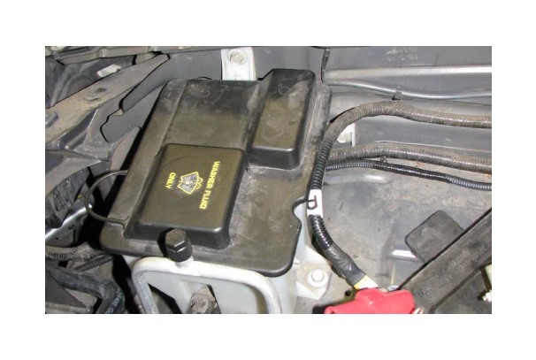
45. Reinstall the washer fluid reservoir being careful not to pinch the newly installed wire harness.
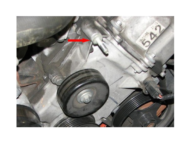
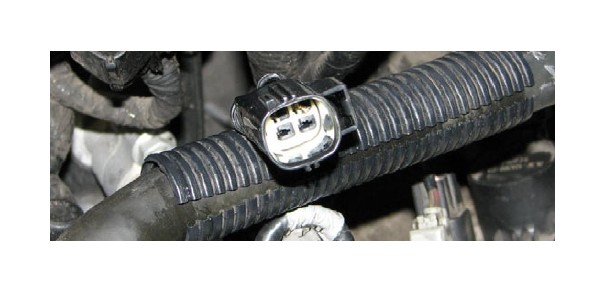
46. Locate the heated PCV connector on the driver side of the engine harness and attach the supplied water pump wiring harness connector.
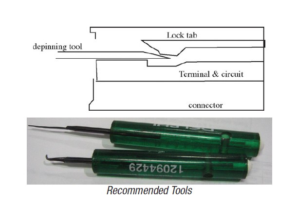
NOTE: Edelbrock is in the process of acquiring OEM harness connectors to supply with superchargers. Compare the connectors you have recieved with those on the vehicle. If they match, you may skip the following TPS depinning procedure.
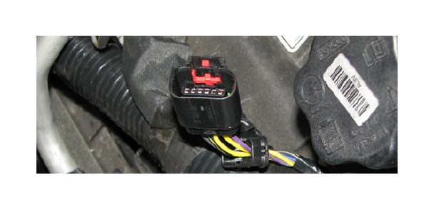
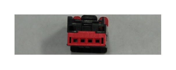
47. Locate the TPS electrical connector. Use a small screwdriver or pick to push the lock tab to the side and remove the red wedge lock. Identify the wire coloring for each pin location then use a depinning tool, needle or safety pin to slide under the terminal and lift the locking tab while pulling gently on the corresponding wire to depin the connector.
48. Insert each wire into the same pin location it was in previously into the supplied connector. Snap the wedge lock down on the supplied connector once all wires have been installed to secure them in place.
49. Attach the TPS extension harness to the newly pinned connector.
50. Remove the electrical connectors from each of the ignition coil packs.
51. Use a 7mm socket to remove the bolt that secures the coil pack to the valve cover. Pull the coil pack out and set it to one side to access the spark plug. Use a 9/16” spark plug socket to remove the stock plug.
52. Apply anti-seize to the threads and dielectric grease to the terminal end of the supplied spark plug. Install the new plug in the cylinder head and reinstall the coil pack. Repeat this procedure for each plug, keeping the coil packs in the same order on the engine.
53. Disconnect the overflow hose from where it connects to the radiator.
54. Disconnect the coolant hose at the bottom of the coolant reservoir tank.
55. Position a drain pan below the radiator then disconnect the lower radiator hose from the radiator.
56. Unbolt and remove the idler pulleys on the driver side.
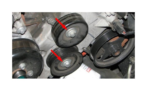
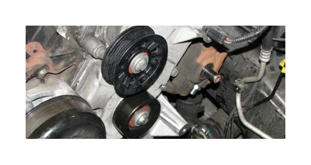
57. Use the stock bolts to install the supplied idler pulleys on the two front cover bosses. Note that the smooth 65mm pulley goes on the lower boss.
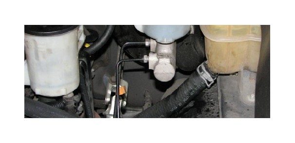
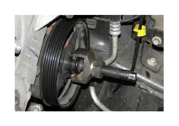
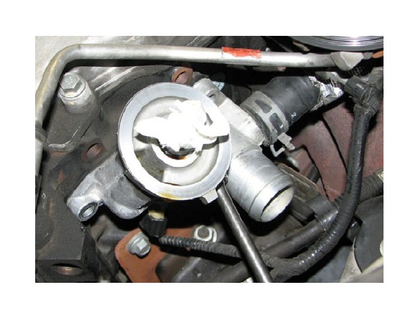
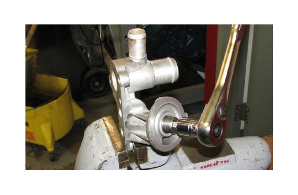
58. Use a pulley removal tool to remove the power steering pump pulley.
59. Use a turkey baster, hand pump or siphon to drain the power steering fluid reservoir.
NOTE: Several of the following steps are more easily accomplished by working from below the truck. A service lift is the preferred method of accessing the undercarriage, but appropriately load-rated jack and jack stands will work, as well.
60. Position a drain pan below the oil filter and power steering pump then remove the oil filter and allow engine oil to drain. It is not necessary to fully drain the oil pan.
61. Use a 10mm socket to unbolt and remove the oil splash shield.
62. Remove the lower radiator hose from the engine.
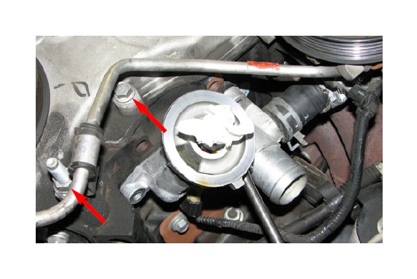
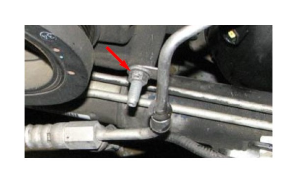
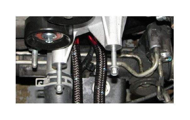
63. Use a 15mm deep socket to remove the stud securing the power steering hard line to the front cover and a 12mm socket to remove the bolt directly above it.
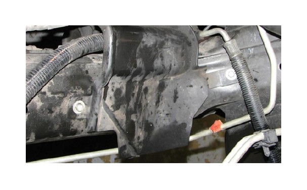
64. Use a 10mm socket to remove the bolt securing the power steering pressure line to the crossmember.
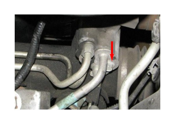
65. Use an 18mm wrench to remove the power steering pressure line from the under side of the pump.
66. Use a flat bladed screwdriver to pry the locking tab on the power steering pressure sensor connector up slightly and pull it off the sensor.
67. Use a 10mm wrench to remove the nut that retains the power steering hard line bracket.
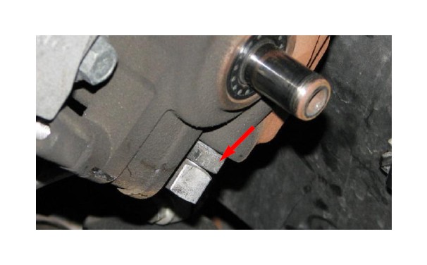
68. Use a 10mm socket to remove the bolt that holds the power steering line retention bracket in place. Save this bolt for later reuse.
69. The power steering pressure line can now be pulled out of the steering box. Remove the pressure sensor and set it aside, the rest of the line can be discarded.
70. Depress the locking tab and pull the electrical connector off the oil pressure sensor.
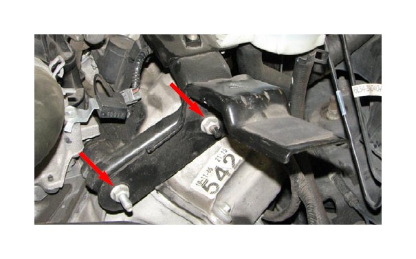
71. Use a 10mm universal socket and an extension bar to remove the four bolts that retain the oil filter bracket to the side of the engine block. Remove and save the gasket for reuse later.
72. Use a 21mm wrench to remove the oil pressure sensor from the filter bracket.
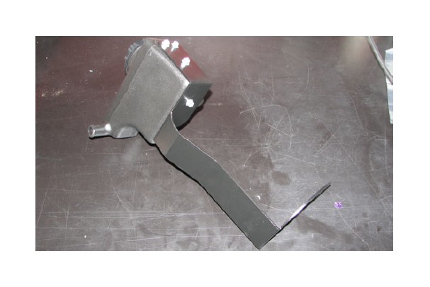
NOTE: 4wd trucks will need to use the bracket supplied with the #15834 kit, as shown in the following steps. 2wd trucks should use the bracket supplied in #1581 supercharger box.
73. Apply thread sealant to the threads of the oil pressure sensor and install it in the supplied filter bracket.

74. Apply thread sealant to the supplied hose fitting then install it in the oil filter bracket. Attach the coolant hose that ran from the overflow reservoir to the hose fitting installed in the bracket.
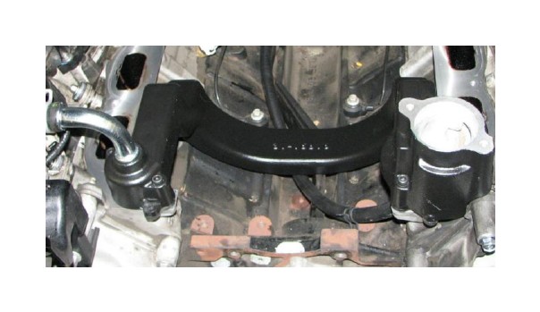
75. Place the oil filter bracket gasket on the flange of the supplied bracket and hold it in place using the long M8 x 75mm bolts supplied in Bag #3. Feed the coolant hose attached to the bracket up around the block to the reservoir tank while the supplied bracket is maneuvered into place. Once the bracket is close enough, attach the electrical connector to the oil pressure sensor.
76. Once the flange of the supplied bracket is aligned with the block, install the two short M8 x 35mm bolts also supplied in Bag #3. Finger tighten all four mounting bolts until the bracket is flush to the block. A swivel 10mm socket and extension bar are strongly recommended to facilitate installation of the bottom bolt.
77. Install the supplied 76mm idler pulley to the front boss of the oil filter bracket with the M8 x 90mm bolt and washer supplied in Bag #3. Only snug the bolt at this time.
78. Tighten down the four mounting bolts, then tighten the pulley bolt. Verify that the pulley can spin freely once all the filter bracket bolts have been tightened.
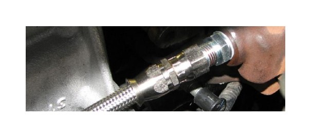
79. Use an 18mm wrench to install the supplied fitting into the power steering pump then torque it to 48 ft-lbs.
80. Install and tighten the fitting on the short side of the supplied power steering hose onto the fitting in the pump.
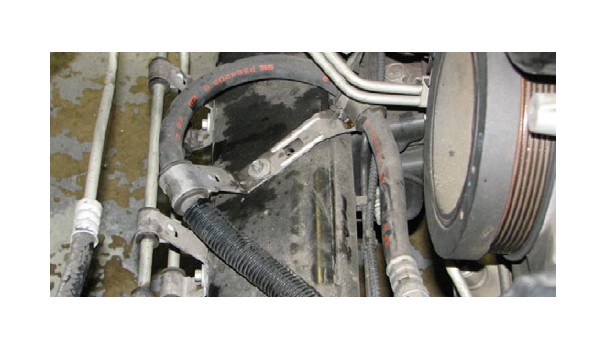
81. Route the power steering hose along the crossmember and back to the power steering rack. Secure it to the crossmember with the stock bolt and supplied bracket.

82. Tighten the supplied smooth fitting onto the other end of the power steering pressure line then insert it into the power steering rack. Use the stock bolt and supplied bracket to secure the fitting to the rack. Install the stock pressure sensor in the line and attach the connector.
83. Use a 1/2” allen wrench to remove the oil filter fitting from the stock oil filter bracket. 2wd trucks will install it in the supplied oil filter bracket while 4wd trucks will install it in the remote filter bracket supplied with #15834.
84. 2wd trucks should now install the oil filter on the new bracket, while 4wd trucks should refer to the instructions supplied with the #15834 kit.
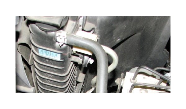
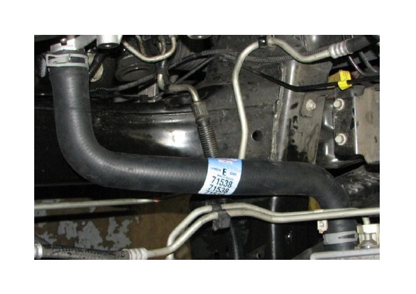
85. Install the supplied lower radiator hose to the oil filter bracket and the radiator and secure both ends with the stock hose clamps.
86. Use pliers or a hose clamp tool to attach the hose from the oil filter bracket to the bottom of the coolant overflow reservoir.
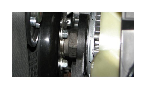
87. Use a pulley installation tool to reinstall the power steering pump pulley.
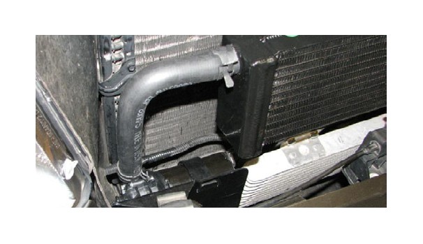
88. Install the M8 x 45mm alternator bolts supplied in Bag #3 into the new oil filter bracket.
89. Remove the nut and install the power wire so that the harness extends in the opposite direction as the alternator mounting ears. Tighten the nut once the power wire is properly oriented.
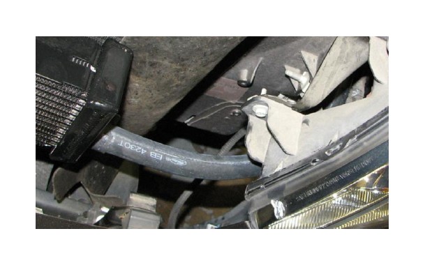
90. Install the alternator electrical connector.
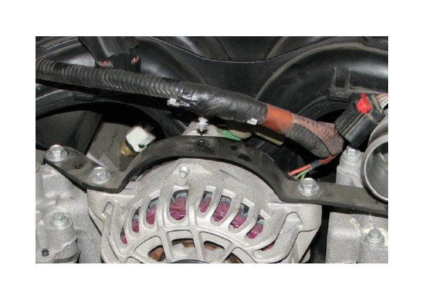
91. Loop the supplied serpentine belt around the alternator pulley with the ribbed side facing the pulley and the belt going around the upper bolt boss of the bracket. Lift the alternator into place and snug the mounting bolts but do not fully tighten them at this time.
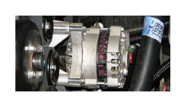
92. Position the two supplied alternator support straps so that they align with the bolt provisions on the alternator and the oil filter bracket. Snug the supplied strap bolts, then hold the alternator firmly against the bracket while torquing the bracket bolts to 18 ft-lbs, then torque the strap bolts to 8 ft-lbs. Make sure the belt stays between the strap and the upper bolt boss.
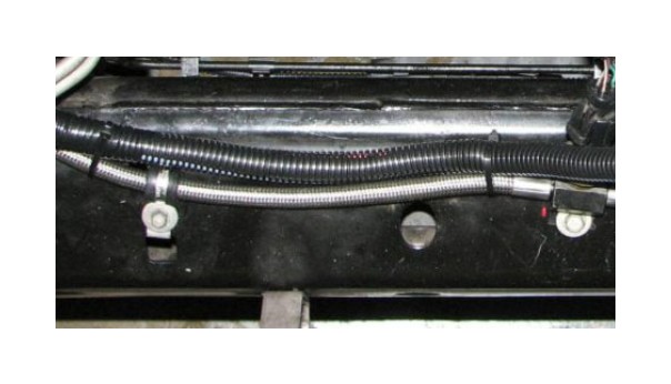
93. Route the alternator power wire parallel to the power steering line and up to the positive battery terminal. Attach the ring terminal to the power stud with the stock nut. Use the supplied zip ties to secure the alternator power wire harness to the power steering line.
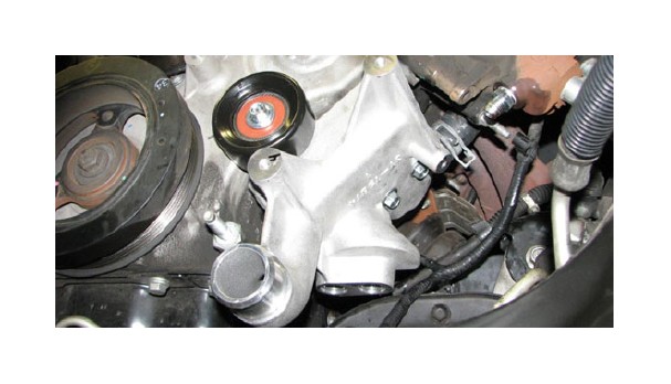
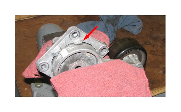
94. Remove the three bolts holding the belt tensioner in place, and remove the tensioner.

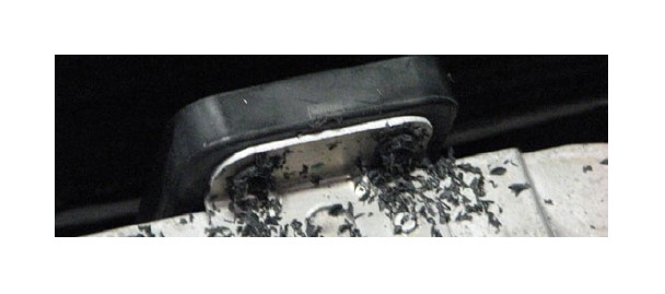
95. Place the tensioner in a cloth wrapped vice and use a grinding wheel or hacksaw to remove the stop.
96. Use a grinding wheel or file to ensure that the area that was ground down is smooth and free of burrs.
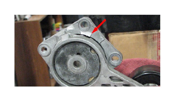
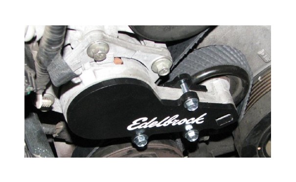
97. Align the two pieces of the tensioner brace so that the bolt holes line up and the script is facing out then install the three M6 x 25mm bolts supplied with the brace.
98. Use the stock bolts to reinstall the tensioner.
99. Remove the tape covering the water passages in the cylinder heads. Apply the stock gaskets to the new water crossover, then lower the crossover onto the heads. Install the M6 x 45mm bolts supplied in Bag #4 and torque them to 8 ft-lbs.
100. Remove the tape covering the intake ports of the cylinder heads.
101. Carefully remove the intake gaskets from the intake manifold by pushing the clips out of each flange hole.
102. Install the gaskets onto the runner flanges of the supercharger assembly. Note that not every lock tab will have a corresponding hole.
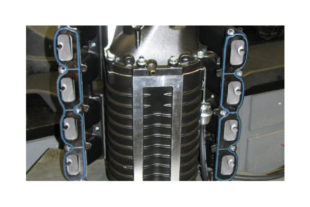
103. Lift the supercharger assembly, with the flange gaskets in place, over the water crossover and onto the engine. Insert the M6 x 30mm manifold bolts supplied in Bag #1 into their provisions to determine when the manifold is properly aligned
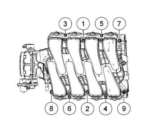
104. Torque the manifold bolts to 89 in-lbs. in the sequence shown below.
105. Apply a small amount of o-ring lube to each injector and line them up with the injector provisions in the supercharger. Push down on the fuel rails until all of the injectors are seated in the manifold then install the four supplied hold down bolts.
106. Attach the eight fuel injector electrical connectors to their respective injectors.
107. Push the stock fuel supply hose onto the fuel rail inlet fitting until it clicks into place then reattach the lock clip.
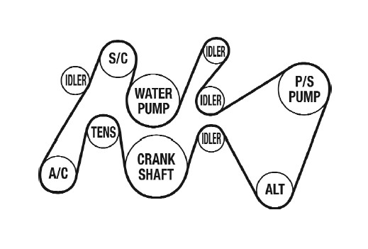
108. Route serpentine belt according to diagram. Insert a breaker bar into the tensioner and apply pressure to slide belt onto final pulley.
109. Use pliers or a hose clamp tool to attach the heater hose to the new water crossover.
110. Reattach the fuel pressure sensor connector and vacuum line running from the supercharger.
111. Remove the inboard and rear strut tower nuts on the passenger side. Lift the clip holding the nearby cable housing until it seperates from the fender.

112. Mount the intercooler reservoir to its mounting bracket using the M6 x 16mm bolts supplied in Bag #5. Attach the Reservoir to Pump molded hose to the lower fitting of the reservoir so that it can be routed down and around the radiator on the passenger side and secure it with a hose clamp supplied in Bag #5.
113. Install the intercooler reservoir so that the bracket is on the strut tower studs. Reinstall the strut tower nuts and torque them to 30 ft-lbs.
114. Install the Supercharger to Reservoir hose between the intercooler reservoir and the passenger side of the supercharger and secure both ends with the hose clamps supplied in Bag #5.
115. Use a 90° drill to drill out the four plastic rivets holding the oil cooler in place. (Early trucks have metal brackets rather than plastic, but the procedure is the same.)
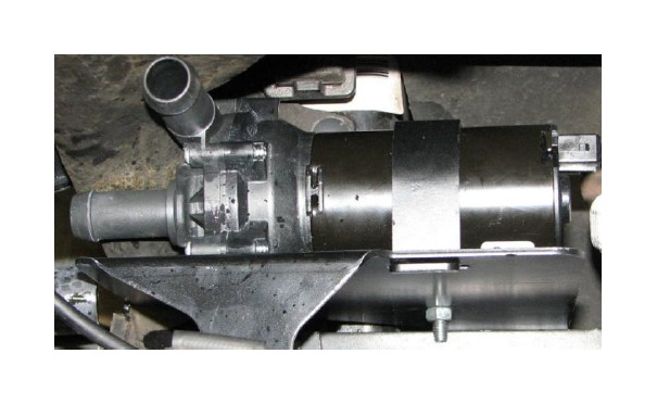
116. Install the water pump into the water pump bracket so that the pump outlet will point up when installed and the pump inlet points toward the passenger side fender. Secure the water pump to the bracket using the strap and the M8 x 30mm bolt supplied in Bag #5.
117. Reach up from below the truck to install the water pump bracket to the passenger side bumper bolt.
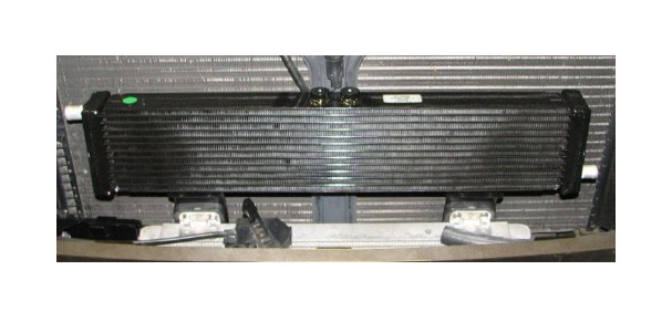
118. Mount the heat exchanger brackets to the oil cooler brackets and attach with the supplied hardware.
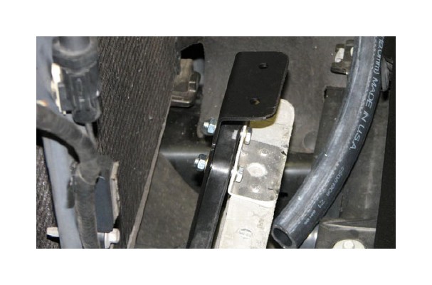
119. Mount the heat exchanger on the new brackets and attach it with the upper bracket and supplied hardware.
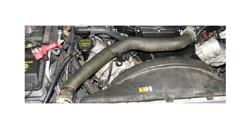
120. Attach the molded hose to the water pump inlet and secure it with hose clamps. Trim the passenger side radiator shroud so that it clears the hose.
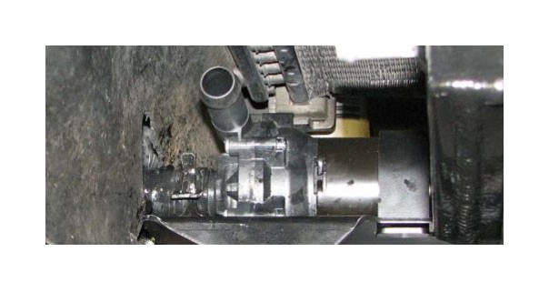
121. Mount short hose from water pump outlet to heat exchanger inlet and secure with hose clamps.
122. Attach the long hose on the driver side to the heat exchanger outlet and secure it with a clamp. Trim the driver side radiator shroud so that it clears the hose. Route the other end of the hose around the radiator and up to the driver side of the manifold, making sure it clears all exhaust, suspension and steering components.
123. Attach water pump harness connector to pump.
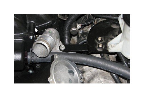
124. Attach the EVAP hose to the lower nipple on the driver side of the manifold air inlet, behind the throttle body flange. Attach the driver side PCV hose to the other fitting directly above it.
125. Attach the long section of 3/4” hose to the driver side nipple at the front of the supercharger.
126. Install the stock thermostat, o-ring and housing on the new water crossover and install the stock bolts.
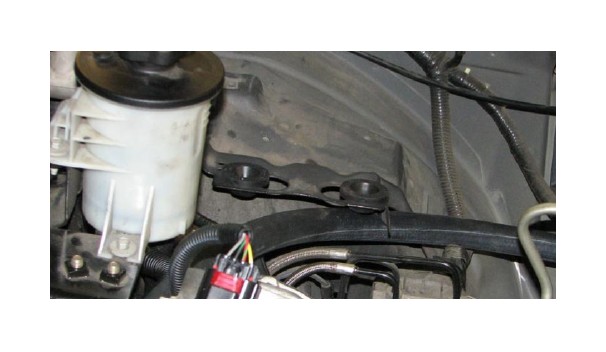
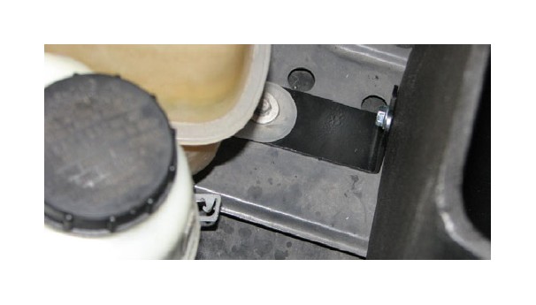
127. Install the power steering reservoir strap between the thermostat housing and the power steering reservoir bracket and secure it using the stock bolts.
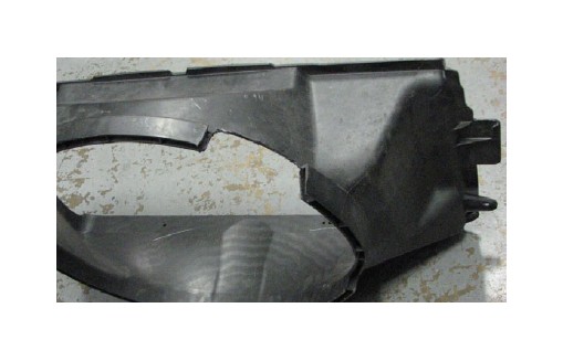
128. Use a cut-off wheel to trim the radiator fan shroud as shown to clear the alternator.
129. Lower fan and shroud into engine bay together and reinstall clutch fan.
130. Reinstall the fan shroud using the stock hardware then reinstall the radiator cover and secure it with the stock body pins.
131. Reinstall the stock upper radiator hose between the thermostat housing and radiator and secure it with the stock hose clamps.
132. Remove plastic sheet from supercharger air inlet and install supplied throttle body o-ring on flange.
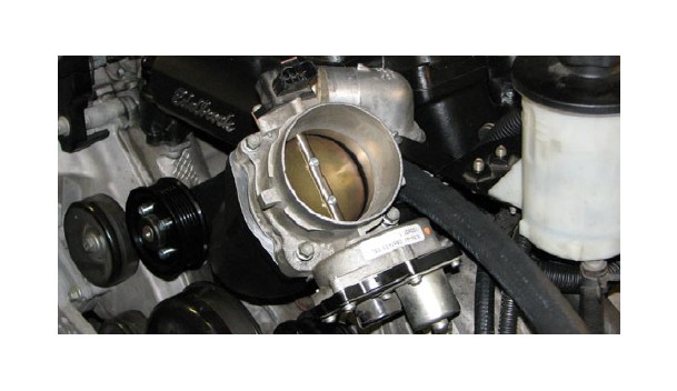
133. Install the stock throttle body onto the inlet flange with the stock bolts so that the ETC motor motor is on the driver side.
134. Insert supplied rubber grommets on air inlet bracket.
135. Install the molded airbox onto the air inlet bracket so that the heat exchanger hose and wire harness fit below it in the provided groove. Secure the airbox with the supplied bracket to the coolant overflow reservoir.
136. Insert the coolant overflow hose through the airbox in the hole provided and reattach it to the radiator.
137. Insert the MAF housing into the large hole in the shroud so that the MAF sensor provision is oriented towards the back of the engine bay. Secure the housing to the shroud with the three M6 x 12mm bolts supplied in Hardware Bag #6.
138. Install the stock Mass Air Flow Sensor (MAFS) into the supplied housing and secure it with the #8-16 x 3/8” Torx bolts supplied in Hardware Bag #6. Verify that the arrow on the sensor points toward the throttle body.
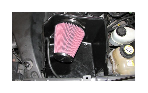
139. Install the large conical air filter onto the MAF housing inside the shroud and secure it with the supplied hose clamp then install the supplied edge trim along the top of the shroud.
140. Insert the silicone elbow between the throttle body and the MAFS housing and secure it with the supplied worm clamps.
NOTE: The following depinning procedures may also be skipped if the supplied connectors match OEM.
141. Locate the MAFS electrical connector near the driver side fender. Use a small pick to release the lock tab and raise the wedge lock.
142. Make a note of the color of the wires going into pin locations 1 and 2, then de-pin just those two wires from the connector. Push the wedge lock down once those two wires are out.
143. Locate the small connector attached to the supplied Temp extension harness and remove it. Use a small pick to raise the wedge lock then insert the wires removed from the MAFS connector into the supplied connector in the same order that they were removed.
144. Attach the stock MAF sensor connector to the Temp extension harness then plug the short end of Temp extension harness into the MAF sensor.
145. Route the long end of Temp extension harness to the sensor at the top of the supercharger, towards the rear, and plug it in.
146. Locate the stock ETC connector. Use a small pick to release the lock tab and raise the wedge lock.
147. Make a note of the color of each wire and its pin location. Depin the connector and install the wires into the connector supplied on the ETC extension harness in the same pin locations they were in previously.
148. Attach the ETC extension harness to the newly pinned connector then attach the other end of the harness to the ETC connector on the throttle body.
149. Attach the TPS extension harness connector to the TPS on the throttle body.
150. Install the supplied PCV hose between the passenger side valve cover barb and the fitting on the silicone throttle body elbow and attach both ends.
151. Install the supplied 3/8” hose onto the brake booster barb and route it to the 90° fitting at the front of the air inlet and secure both ends with the supplied clamps.
152. Verify that the coolant petcock is closed, then refill the coolant system.
153. Fill the intercooler system with a 50/50 blend of water and coolant poured into the recovery tank. Fill the tank until the water level is roughly 1” from the top of the threaded neck.
154. Refill the power steering reservoir with power steering fluid and pour half a quart of engine oil into the oil fill tube (provided the new oil filter was installed dry).
155. Turn the ignition key to the ‘ON’ position but do not start the engine.
156. Verify that water is flowing briskly through the recovery tank, then install the cap. If water is not flowing, turn the key off and on again to bleed the system.
157. It is recommended that you check the Edelbrock website (http://www.edelbrock.com/automotive_new/mc/ superchargers/fuel_injected_soft-tech.shtml) to confirm that you have the latest calibration. Once you have found the latest tune on the site, power on the programmer, press the left arrow and select the Device Info option. Scroll down to Tune Version and compare that number to the one on the site. If they are different, download the new calibration with the supplied USB cable.
158. Connect the supplied PCM cable to the OBD-II connector located below the steering wheel in the passenger compartment.
159. Use directional pad to highlight Program Vehicle option and press Select button.
160. Use directional pad to highlight Preprogrammed Tune option and press Select button.
161. Read disclaimer then press Select to continue.
162. Verify ignition is in the ‘Key On’ position but that the engine is not running then press Select.
163. Use directional pad to highlight your vehicle and transmission combination then press Select.
164. Use directional pad to highlight your vehicle and transmission combination then press Select, again.
165. Use directional pad to highlight Begin Program then press Select.
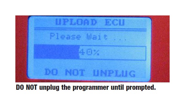
166. Turn the truck off when prompted to do so by the handheld programmer.
167. Read parting message from programmer then press Select to continue.
168. Unplug the programmer cable from the OBD-II port.
169. If you have access to a diagnostic scan tool, run a ‘Key On, Engine Off’ test to verify that all connectors are properly installed, otherwise move on to the next step.
170. Start the truck and verify a smooth idle. If you are using a diagnostic scan tool, run a ‘Key On, Engine Run’ test.
171. Carefully inspect the fuel rail and fuel hose fittings for any leaks. Shut off the engine immediately and make repairs as necessary before continuing if any leaks are detected.
172. Check all fluid levels before operating vehicle.
