 FREE 1 to 3-Day Delivery on Orders $149+ Details
How to Install dB Performance by Corsa 3 in. Sport Cat-Back Exhaust w/ Polished Tip - Single Side Exit (07-13 6.2L Silverado 1500) on your Chevy Silverado
Tools Required
- Safety Glasses
- Small flat head screw driver
- 15mm socket and ratchet
- Chain style pipe cutter or reciprocating saw
- Grommet pullers
- Spare tire removal kit
- Soapy water
- Torque wrench
- Tape measure
- Black marking pen
- 1/2" socket
- Chain style pipe cutter
- Safety glasses
- Torque Wrench

Shop Parts in this Guide
Please take time to read and understand these installation instructions.
We recommend that the installation of this system be performed by a qualified service center or professional muffler installer who has the necessary equipment, tools and experienced personnel. However, if you decide to perform this install, the use of a hoist and an additional person will be required.
CAUTION: Never work on a hot exhaust system. Allow time for the vehicle to cool. Always wear eye protection when working under a vehicle.
Please confirm that all parts are present before beginning the factory exhaust system removal and dB Performance Exhaust system installation.
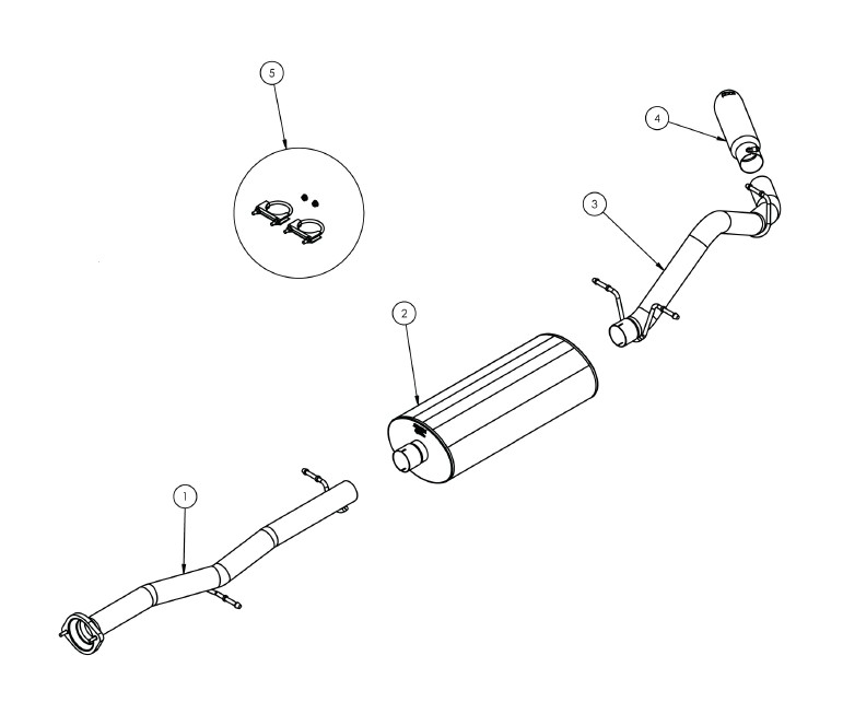
Part #24514
Bill of Materials:
1- Headpipe Assembly (16SE4349)
2- Muffler Assembly (16SE2025) 3-Tailpipe Assembly (16SE4307)
4- dB Slash CutTip (16SE3023)
5- Hardware Kit (16TA7205)
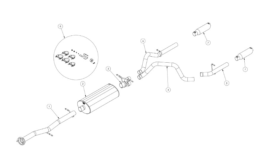
Part #24516
Bill of Materials:
1- Headpipe Assembly (16SE4349)
2- Muffler Assembly (16SE2025)
3- Dual "Y" Assembly (16SE4309)
4- DriverTailpipe Assembly (16SE4317)
5- DriverTailpipe Assembly (16SE4316)
6- PassengerTailpipe Assembly (16SE4315)
7- dB Slash CutTip (16SE3023)
8- Hardware Kit (16SE7256)
Removal of Stock System:
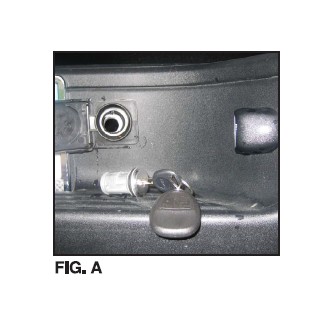
1) Open cover next to rear license plate and use vehicle key to remove lock and access to spare tire removal shaft (See Fig. A)
2) Use the spare tire removal kit from your vehicle and place the square end into the spare tire removal shaft then turn the wrench counter clock wise to lower the spare tire.
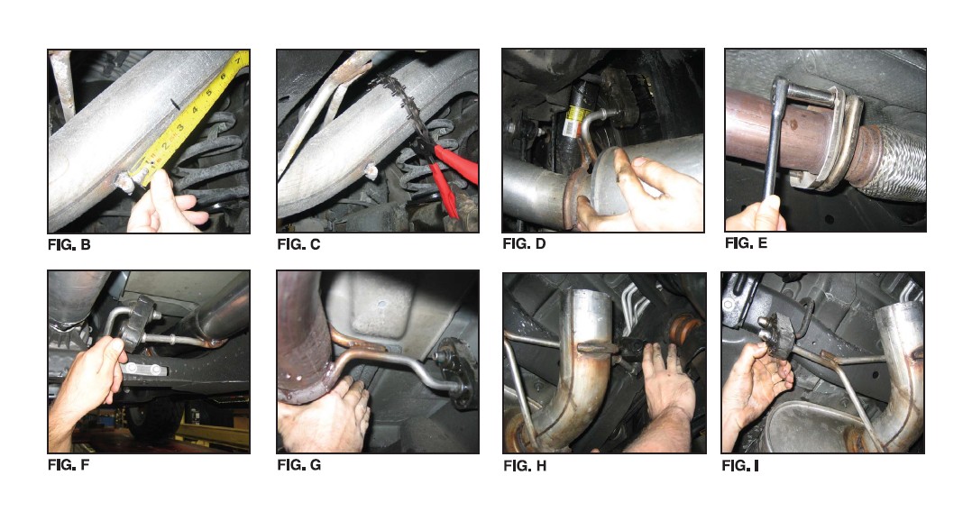
3) Mark tailpipe 3.25" rearward of the 2nd hanger after main tunnel muffler. Place a chain style cutter around the tailpipe at mark and cut the tailpipe at this location. (See Fig. B & C) A reciprocating saw may also be used.
4) Remove the rearmost hanger from the grommet using grommet pullers or similar device. (See Fig. D)
5) Remove the tailpipe section from the vehicle by lifting the tailpipe over the rear axle and backwards under the rear bumper.
6) Use a 15mm socket and ratchet to remove the flange nuts at the flange connection of the head-pipe. Then remove the hangers at the headpipe location and the hangers after the muffler. Remove the tunnel muffler section away from the vehicle. This completes the removal of the stock system. (See Fig's E, F, G, H & I)
Installation of dB Performance Exhaust System:
NOTE: The supplied double edge clamps in this system will crush and permanently deform the exhaust piping as they are tightened. DO NOT tighten these clamps any more than is necessary to lightly hold the exhaust components in place, until the very end of this installation process. It will be difficult or impossible to make any positional or rotational adjustments to the exhaust system after these clamps have been tightened down.
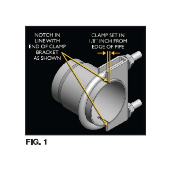
VERY IMPORTANT: Align all clamps so that the open edge of the clamp bracket is parallel and aligned with the notch in the pipe, and the outside edge of the clamp bracket is approximately 1/8" from the end of the pipe expansion. (See Fig. 1) Failure to properly position or orient the clamps could result in a weak clamping load, or even a potential leak at the clamp joints.
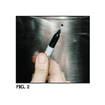
IMPORTANT: Make sure that the small drain holes in the muffler are facing down when the muffler is installed. (See Fig. 2)
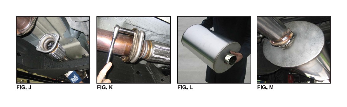
1) Locate the Head Pipe assembly and slide the flange studs into the factory flange. Use the nuts supplied with the hardware kit and evenly tighten down to 45 Ft-lbs. Insert the hangers in to the factory grommets. (See Fig's J & K) Note: Using a soapy solution on the grommet hole will make the job easier.
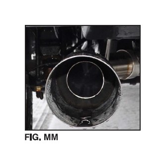
2) Slide the muffler onto the Head Pipe and pre-tighten the clamp. (See Fig's L and M) Slide a supplied 3" clamp over the inlet of the muffler.
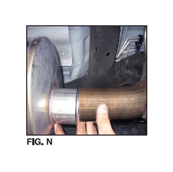
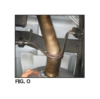
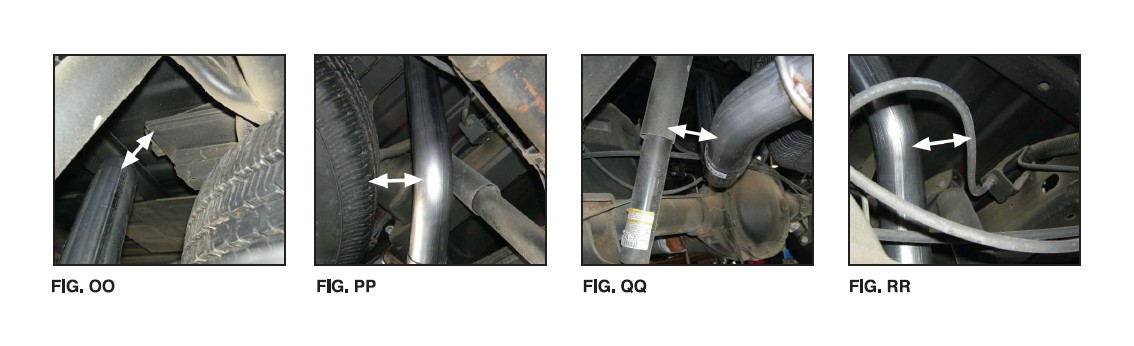
3) Locate the dB Tailpipe. From the rear of the vehicle slide the pipe over the axle while holding the rear differential vent hose out of the way. Insert the pipe over the muffler exit and place the hangers into the factory grommets. (See Fig's N, 0 & P) Slide a supplied 3" clamp over the inlet of the Tailpipe. Note: Using a soapy solution on the grommet hole will make the job easier.
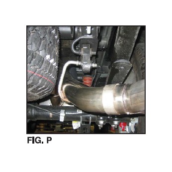
4) Locate the dB Performance straight tip assembly, which has a clamp built into it. Slide the clamp end of the tip onto the end of the tailpipe. (See Fig. Q) Rotate the tip until the dB Performance logo is centered on the top side of the tip. (See Fig. R) Snugly tighten the clamp as shown using a 15mm socket and ratchet, making sure to only tighten the clamp enough to hold the tip in place on the tailpipe. (See Fig. S)
5) Visually inspect the exhaust system position, tip alignment, clamp orientation and position, and exhaust pipe clearance. Make any necessary adjustments at the slip joints.
6) Starting from the front of the exhaust system tighten all nuts on clamps to 35 ft-lbs using a torque wrench. Torque tip clamp to 45 ft-lbs.
7) Replace the spare tire to the pre-removal condition.
8) It is STRONGLY SUGGESTED that all clamps be checked and re-tightened (if necessary) to the recommended torque after initial road testing of the vehicle, as thermal cycling has occurred on the system. Please wait until system has fully cooled to conduct this process.
This completes the side exit installation.
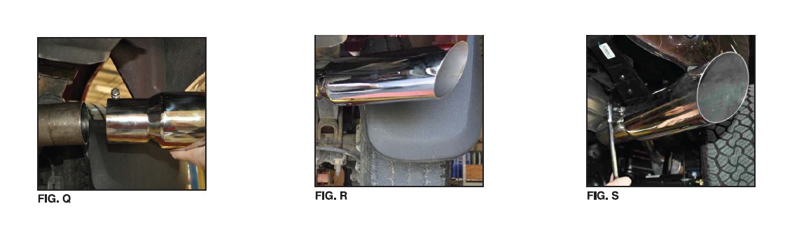
3) Locate the dual "Y" assembly and insert over the muffler exit and place the hangers into the factory grommets. Slide a 3" clamp over the inlet of the "Y" assembly and pre-tighten the clamp. (See Fig's T, U, V & VV)
4) Place the passenger tailpipe assembly onto the upper end of the dual "Y" assembly and insert the hanger into the factory grommet. Slide a supplied 2.5" clamp over the inlet of the Tailpipe. Pre-tighten the clamp at this time. (See Fig's X, Y, Z, & AA)
5) Place the "driver over the axle pipe" assembly onto the lower end of the dual "Y" assembly. Slide a 2.5" clamp over the inlet of the pipe and pre-tighten the clamp leaving the pipe very loose at this time for adjustment when placing the driver side tailpipe onto the over the axle pipe. (See Fig's BB, CC, & DD)
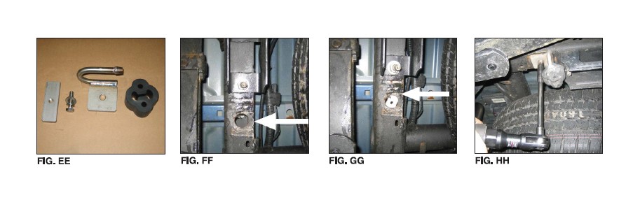
6) Locate Driver Side tail pipe hanger assembly ("U" shaped Wire Loop & Plate) and hardware (threaded Mounting Plate, bolt and washers) (See Fig. EE). On the driver side of the vehicle, position the threaded rectangular-shaped mounting plate on top of the frame rail over the hole located furthest forward from the rear of the frame rail. (See Fig. FF & GG)
7) Insert the supplied 5/16"-18 bolt through the tail pipe Wire Loop & Plate hanger and thread it into the threaded Mounting Plate on top of the frame. Note: Position the driver side hanger so that it faces toward the spare tire (See Fig. HH)
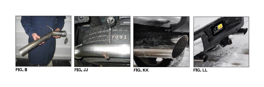
8) Install the driver side tailpipe assembly onto the over the axle pipe (See Fig's II & JJ). Insert the tailpipe hanger into the provided rubber grommet. Slide a 2.5" clamp over the inlet of the tailpipe and pre-tighten the clamp at this time.
Note: Using a soapy solution on the grommet hole will make the job easier.
9) Slide one of the tips over the outlet of the driver side tailpipe. Make sure the etched logo is pointing up and loosely tighten the clamp at this time. (See Fig. KK, LL). Repeat on passenger side.
10) Check the alignment of tail pipes and tips. (See Fig. NN) Make sure there is at least 1.5" clearance between the tips and bottom of the bumper. Align tail pipes if necessary by making adjustments at the slip joints.
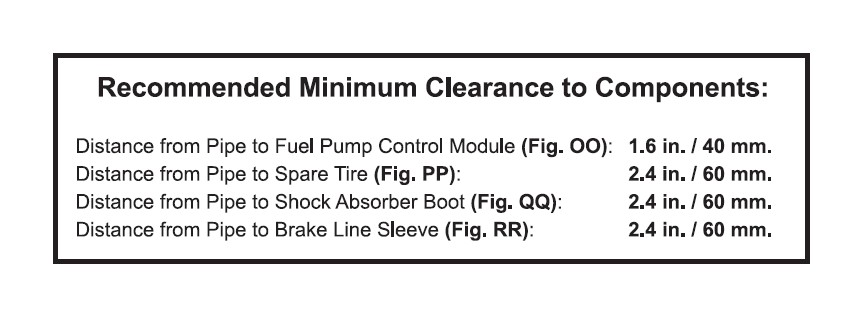
NOTE: Failure to follow these instructions and maintain the recommended clearances to the above listed parts could impact the long term performance of said parts. Please contact the dB Performance Exhaust Customer Service Department (800-486-0999) if you have any questions related to the above information.
11) Starting from the front of the exhaust system, tighten all nuts on u-bolt clamps to 35 ft-lbs using a torque wrench. Tip clamp torque setting: 16-20 ft-lbs.
12) It is strongly suggested that all clamps be checked and tightened if necessary after road testing the vehicle and after the system has cooled.
NOTE: During cold weather start-ups, you may experience an exhaust sound that is deeper and louder in tone than usual. This is temporary and will diminish to normal levels once your engine has reached its normal operating temperature.
NOTE: Immediately following the installation of your exhaust system, you may experience a trace of smoke after initial start-up. DO NOT be alarmed. The smoke is caused by the burning of a small amount of forming oil residue used in the manufacturing process.


