FREE 1 to 3-Day Delivery on Orders $149+ Details
How to Install Putco 10 in. Luminix LED Light Bar on your Ram

Shop Parts in this Guide
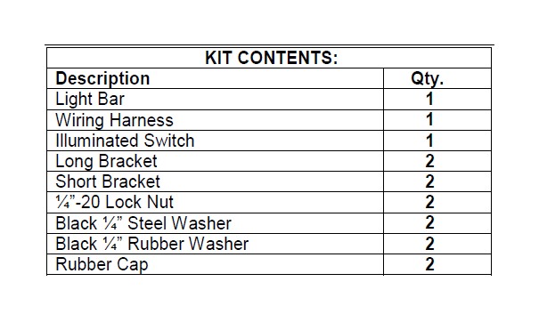
Please read all instructions before installation and to check to see that all parts are included.
Light Bar Installation
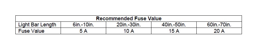
1. Remove light bar from packaging. Check to see if all parts from above table are included.
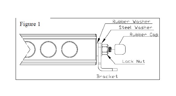
2. Remove rubber cap, lock nut, and steel washer from light bar. Leave rubber washer on, this will go between light bar and bracket.
3. Place selected brackets onto light bar, reinstall hardware as shown in (Figure 1). Tighten nut with 7/16” wrench.
4. Place light bar and mark bracket holes in desired location. Remove light bar and drill holes to the size required for your chosen mounting hardware.
5. Mount light bar with chosen hardware in your desired location.
Wiring Installation
1. Remove wiring harness and switch from kit.
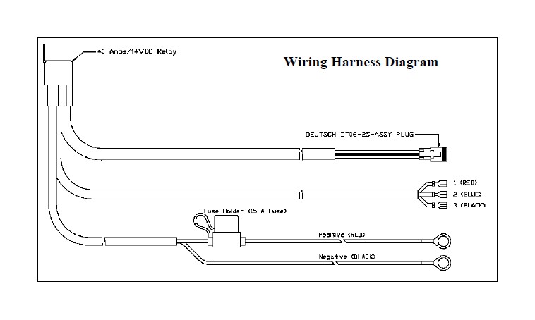
2. Route wiring harness so that the red and black power cables are routed to the battery, the three switch wires are routed to your desired switch location, and the Deutsch plug is routed to the light bar. Keep wiring away from anything that will get hot.
3. Mount relay with desired hardware in a position under hood or in cab that is limited to water exposure.
4. Plug male (on the wiring harness) and female (on light bar) Deutsch plug connectors together.
5. Drill ¾” hole in desired switch mounting location. Verify there will be enough clearance behind switch to plug in the wires. Notch a small slit in the side of the hole using a file. This will keep the switch from turning.
6. Press switch into hole; verify that the notch made in step 5 lines up with the notch on the switch.
7. Plug wires into switch. Prongs on switch will be marked 1 through 3. Red wire goes to prong 1, Blue wire goes to Prong 2, and the Black wire goes to prong 3 (gold prong).
8. Attach power cable to the battery. Red goes to positive and black goes to negative.