FREE 1 to 3-Day Delivery on Orders $149+ Details
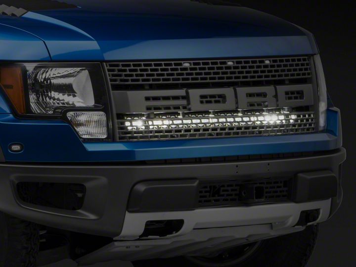
How to Install Baja Designs OnX6 40in. LED Light Bar w/ Upper Grille Mounting Brackets on your F-150
Shop Parts in this Guide
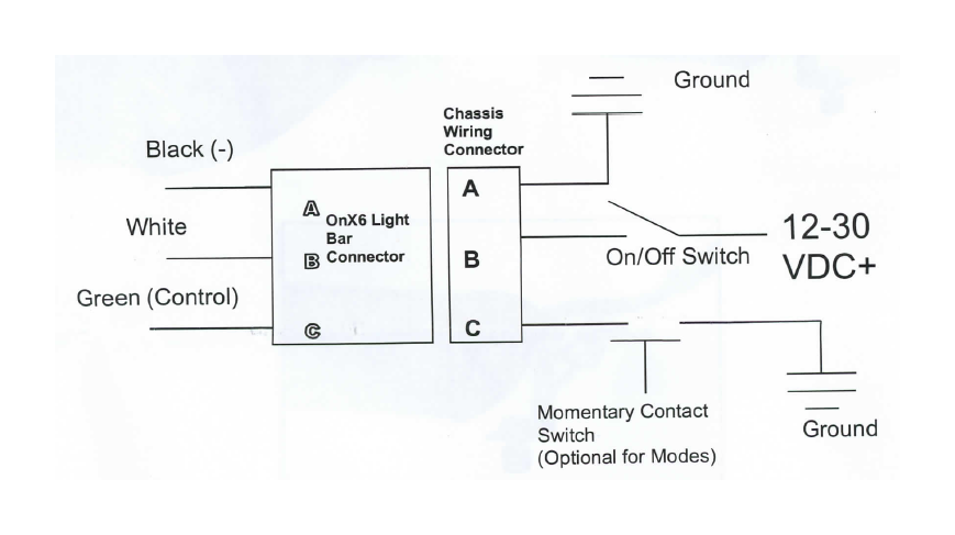
Baja Designs OnX6 Wiring
All OnX6 Light bars have a microprocessor that performs thermal management of the LED's and allow a dimming mode and a strobe mode. If you want to use the dimming and strobe modes of the light bar, a separate momentary contact switch is required. If you do not need this feature, then a single standard on/off switch is all that is required.
Connector Wiring (WeatherPak 3 Pin Connector)
When using the optional Momentary Switch, quickly depressing the switch will dim the light to 50% power. Depressing the switch again will toggle back to full power.
For Strobe mode, hold switch for two seconds.
Moisture Block: The Moisture Block functions exactly to its name, completely blocking moisture or water from climbing its way down the cord into your LED light. You can even cut the connector off without voiding your warranty.
Baja Designs S8 Wiring
All S8 Light bars feature off/on and a unique backlit feature. To operate the backlit feature a second off/on switch will be required. If you do not need this feature, then a single standard on/off switch is all that is needed.
Connector Wiring (WeatherPak 3 Pin Connector)
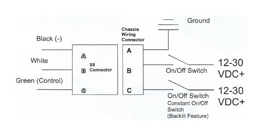
When using the optional backlit feature, depressing the switch will turn on the backlit feature. Depressing the switch again will turn the backlit light off.
Moisture Block: The Moisture Block functions exactly to its name, completely blocking moisture or water from climbing its way down the cord into your LED light. You can even cut the connector off without voiding your warranty.
Baja Designs chooses stainless steel mounting bolts and hardware for their corrosion resistance and appearance. Stainless fasteners can be prone to galling or sticking during installation so we recommend a thread lubricant or anti-seize on the threads when assembling. Avoid using high speed power tools to assemble because the heat generated from friction can promote seizing.