FREE 1 to 3-Day Delivery on Orders $149+ Details
How to Install Barricade Raptor Style Fender Flares on your F-150
Installation Time
1 hours
Tools Required
- Stubby Ratchet
- 10 mm socket
- 5.5 mm socket
- Phillips head screw driver
- #2 Phillips head bit
- Utility knife
KIT INCLUDES
Front Flares
Rear Flares
Plastic Rivets
LED lights w Harness
Rubber Edge Trim
Long speed clips
Short speed clips
L Mounting brackets
8 x 3/4“mounting screws
8 x 1/2“mounting screw
PRIOR TO INSTALLATION
Read these instructions Before beginning the installation
Make sure kit is complete before beginning installation
NOTE: The rear flares are embossed with either a D or P indicating Passenger or Driver. Make sure you match the correct flare to the side of the Truck you are installing.
If you plan on painting your Fender Flares it must be done prior to installation. All surfaces must be cleaned and prepped following the specifications outlined by the paint manufacturer. PLEASE NOTE: Painted flares cannot be returned.
PREPARING FLARES FOR INSTALLATION
STEP 1. Installing Rubber Edge Trim
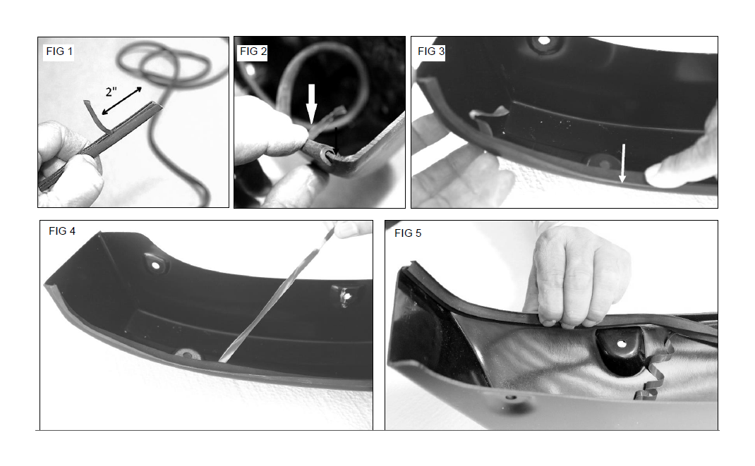
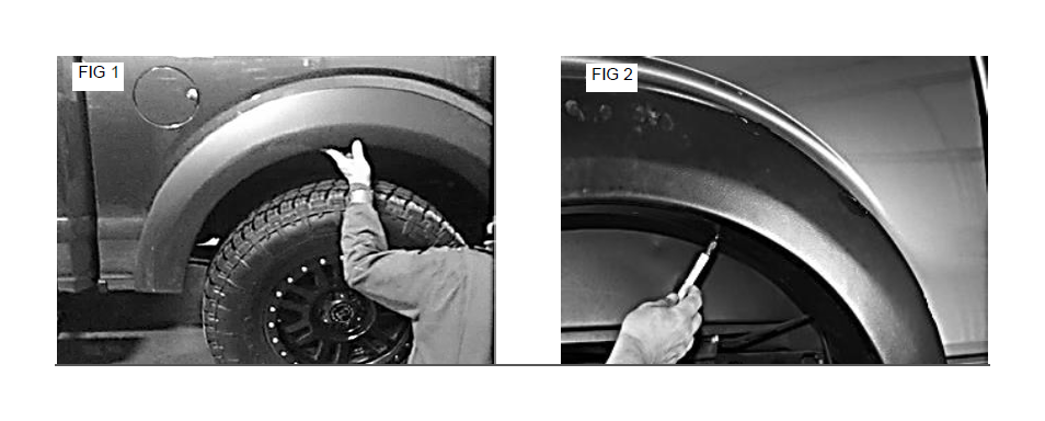
Locate the supplied “U” shaped rubber edge trim. Peel back approx. 2 “of the red lining. FIG 1
Starting at one end of the flare, push the trim onto the edge of flare. Make sure the red liner sits inside the
flare FIG 2
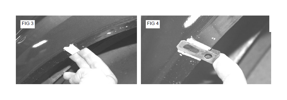
Continue pressing the rubber trim on to the flare in 6” increments. FIG 3
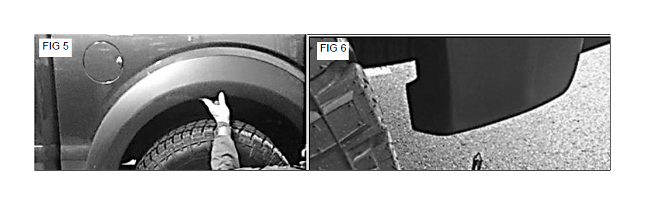
Peel back 6 inches of the red liner and firmly press the trim to bond to the flare. FIG 4 and 5
Repeat steps 3 and 4 until you have gone completely around the flare. Cut the trim to length.
Repeat this process for the remaining flares.
Step 2. LED Light Installation
Take the front driver and passenger side flares to the work bench. Note: Make sure the bench is properly padded to ensure the flares do not get damaged during installation process.
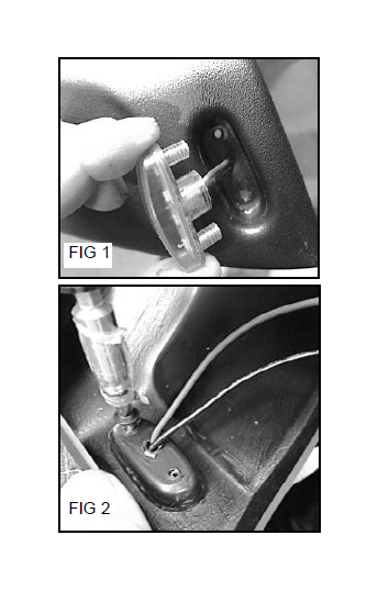
Locate the supplied LED lights. Place the light into the formed pocket at the front of the flare. Push the hot and neutral wires through the center hole in the pocket. Fig.1
Turn the flare over. Adjust LED light until the mounting holes on the lights line up with the holes in the flares.
Locate the supplied # 8 x ½” mounting screws. Using a Philips head screw driver Install 2 screws per light. Fig. 2
CAUTION: Do Not Over-Tighten Screws.
Repeat steps above for the other flare.
NOTE: The flares come complete with LED lights which need to be connected to a power source. If you are not qualified to make the proper connections we highly recommend that you contact an installation expert to complete the connections. The hardware kit comes complete with a wiring harness. This harness can be used to connect the LED lights to your power supply. They are included for your convenience but your specific installation may require additional wiring and other components not supplied in our hardware kit.
INSTALLING FRONT FLARES
Step 1. Supplied Mounting Bracket Installation
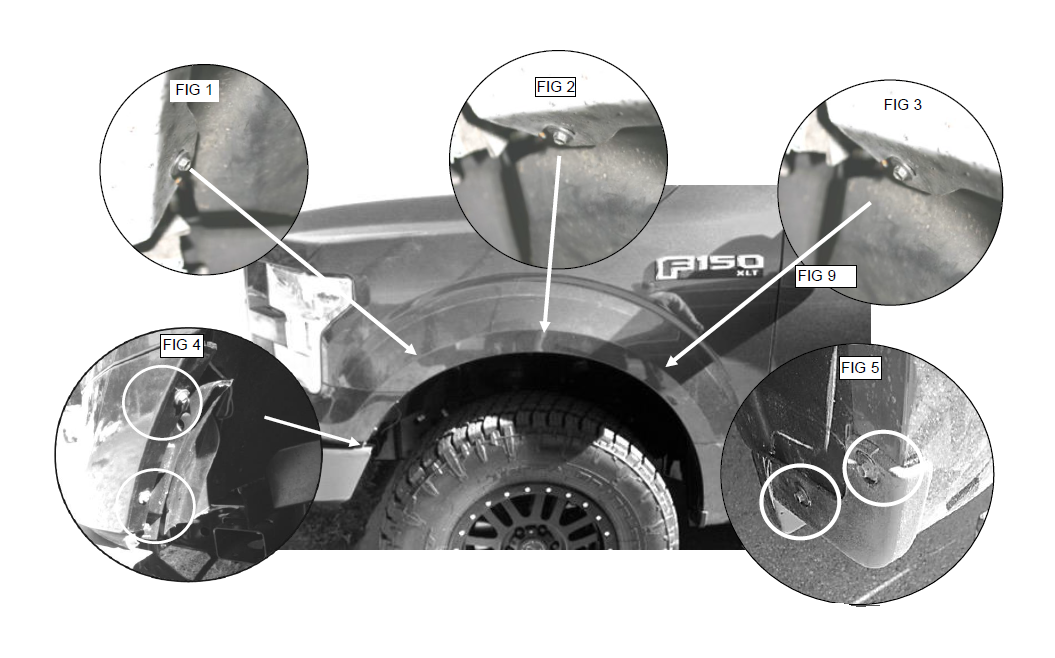
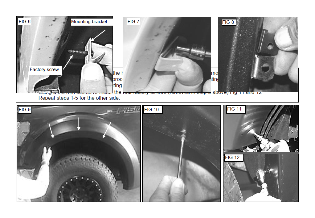
Locate three factory screws on the inner wall of the wheel well lip. Fig. 1,2 and 3
Using a 5.5 mm socket remove and set aside these two screws.
Using a 5.5 mm socket remove two factory screw located at bottom front of wheel well. Fig. 4
Next Remove two factor screws which attach the factory plastic mud guard. Do not discard mud guard. Set screws aside for later use. Fig. 5
Step 2. Slide a factory screw removed in step one through the slot on a supplied mounting bracket. Fig. 6
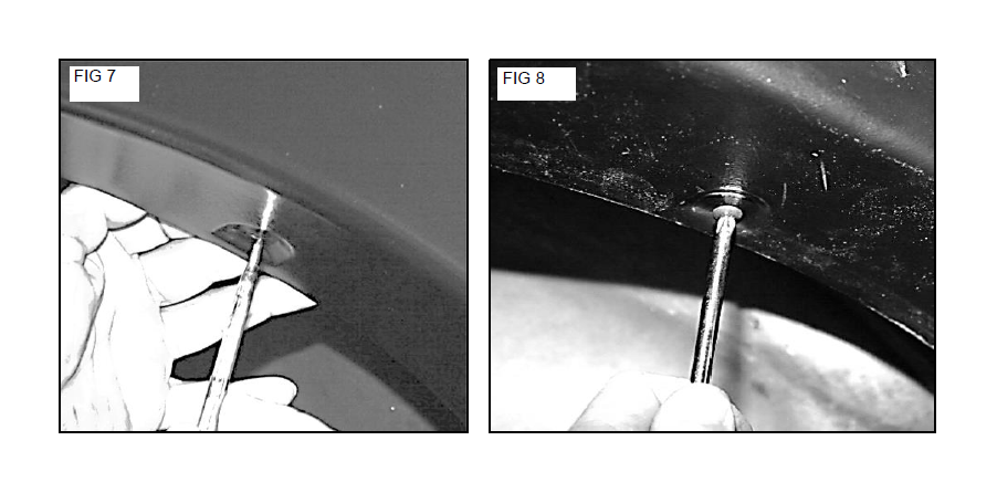
Start the screw into the one of the factory holes and using a 5.5 mm socket tighten the screw unit the bracket is securely mounted. Fig. 7 (Do Not Over tighten screw)
Install the other 2 mounting bracket in the other factory holes by repeating steps above.
Once all the brackets are securely installed, locate a supplied short speed clip and press the clip onto the mounting brackets. Center the hole in the clip with the hole in the bracket. Fig 8
INSTALLING REAR FLARES
Step 1. Have an assistant place the flare on the fender. Adjust the flare for best fit. Fig 1
Using the pilot holes in the flare as a guide place a mark on the lip of the wheel well. Fig 2
Step 2. Remove the flare.
Place a piece of masking tape on the wheel well lip over the marks you made in step 2 above. Fig 3
Slide a Long speed clip over the taped areas. Fig 4
Step 4. Have your assistant place and hold the flare back on the fender. Fig 5
Proceed to the bottom rear hole in the flare. Line up the hole in the flare with the factory hole.
Install the supplied plastic rivet through the flare and into the fender. Fig 6
Step 5. Proceed to the top holes in the flare.
Reach under the wheel well and adjust the long speed clip installed in step 2 above until the hole in the flare lines up with the hole in the speed clip. Tip. Insert a punch into the hole in the flare to help center the speed clip. Fig 7
Firmly push the flare against the fender and install one supplied #8 x 3/4” mounting screw through the flare and into the speed clip. Do not fully tighten screw at this time. Fig 8
Repeat this process for the other holes in the flare always putting pressure against the flare when installing the mounting screw.
Once all screws have been installed proceed to tighten all screws showing care not to over tighten.
Repeat steps above for the other side of the vehicle.