Talk to a Silverado 1500 Sales Tech
1-888-706-1096
M-F 8:30A-11P, Sat-Sun 8:30A-9P
$20K Sweeps! 10 Chances to Win! Enter Daily >

Best Sellers

How to Install Baer Extreme Plus Rear Brake Kit - Black (07-18 Silverado 1500) on your Chevy Silverado

Installation Time

2 hours

American Muscle
Shop Parts in this Guide
Notices – Read and Follow BEFORE ATTEMPTING INSTALLATION
 All installations require proper safety procedures and protective eyewear.
 All installations assume basic mechanical skill and a factory service manual for the vehicle on which the installation is to be performed.
 All references to the “left” side of the vehicle correlate to the driver’s side of the vehicle.
 Any installation requiring you to remove a wheel or gain access under the vehicle requires use of jack stands appropriate to the weight of the vehicle. In all cases, jack stands rated for a minimum of 2-tons is recommended.
 A selection of hand tools sufficient to engage in the installation of these products is assumed, and is the responsibility of the installer to have in his/her possession prior to beginning this installation. All installations, which require removal of hydraulic hoses and/or bleeding of the brakes, require appropriate fitting/line wrenches, safety catch can, and protective eyewear. Other than these items, if unique or special tools are required they will be stated appropriately in the installation step.
 ALWAYS CONFIRM WHEEL FIT PRIOR TO BEGINNING INSTALLATION OF ANY BRAKE SYSTEM OR “UPSIZED” ROTOR UPGRADE! In addition to checking wheel fitment (available online at www.baer.com), always place the actual corner assembly or a combination of the caliper assembly onto the rotor, and into the actual wheel. This procedure will reconfirm proper clearance between the caliper and the wheel before proceeding with the actual installation.
 Returns will not be accepted for systems that have been partially or completely installed. Use extreme care when checking wheel fitment to prevent any cosmetic damage.

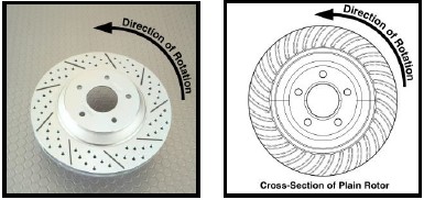
 When installing new Baer rotors, be sure to follow the direction of rotation indicated on the rotor hat area with either an arrow, or an “L” for left, or an “R” for right, or both. “L” or left always indicates the driver’s side of US spec vehicles. Images shown are “L” left rotors:


 A proper professional wheel alignment is required for any system requiring replacement of the front spindles, or tie rod ends. Follow factory prescribed procedures and specifications unless otherwise indicated.
 At any point, stop the installation if anything is unclear, or the parts require force to install. Consult directly with Baer Technical Staff in such instances to confirm details. Please have these instructions, as well as the part number of the component (part numbers are machined into the brackets) that is proving difficult to install, as well as the make, model, and year (date of vehicle production is preferred) of your vehicle available when you call. Baer’s Technical Staff is available from 8:30a.m. - 5:00p.m. Mountain Standard Time (Arizona does not observe Daylight Savings Time) by phone: (602)-233-1411 Monday through Friday.

INSTALLATION:

**Installation Note: Before beginning the installation process it must be noted that vehicles with factory drum brakes follow steps 1-14. Vehicles with factory disc begin at step 9A and follow the rest of the installation process from that point.
For vehicles with factory drum brakes, follow steps 1-14:
1. Support the vehicle with properly rated jack stands and remove the rear wheels. Remove the drums. Sometimes the drums will adhere to the axles due to rust. If this is the case, tapping on the outer edge of the drum with a hammer will shock this loose and allow the drums to be removed.
2. Unblolt the differential cover and remove the differential retaining pin, as shown in Figure 1. Once removed, slide the axles inward and remove the c-clip. Next, carefully slide the axles completely out of the housing so as not to damage the seals.

3. Inspect the bearings, axles, and seals for any wear. Replace as necessary.
4. Disconnect both park brake cables and fluid lines from backing plates. Cap the fluid lines with the supplied vinyl caps.
5. Remove the four bolts holding the backing plate to the housing. Retain these bolts for later use of the park brake assembly installation.
Installation note: A Hardline Retainer Assembly is supplied with the new brake system to provide a fixed mounting point between the new brake hose (supplied) and the factory installed hardline. This will prevent unnecessary movement in the steel line.

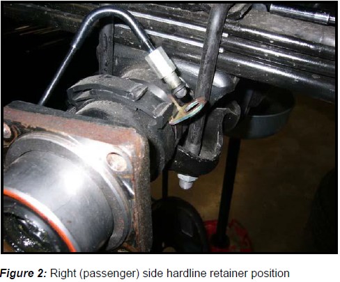
6. Carefully bend the factory hardlines forward and down, as shown in Figure 2. Once completed, install the clamp and hose bracket from the hardline retainer assembly. Figure 2 depicts this process. 


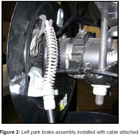
7. Install the new park brake assemblies using the original brake backing plate bolts and torque each bolt to 85 ft∙lbs. Both park brake assemblies are identical. The left (driver’s side) caliper will mount in the “leading” (towards the front of the vehicle) position with the park actuator at the rear of the vehicle. The passenger side will mount similarly. Figure 3 displays the installation of the driver side park brake assembly.


8. Connect park cables as shown in Figure 3. If the cables on your vehicle contain the bead end rather than the loop (the vast majority contain the loop) you will need to purchase the replacement cables from GM. Cab style, bed length, 2 or 4WD will need to be specified. It is recommended to order cables from the 2004 model year. If you have questions on this, please, contact your Baer Brake Systems Tech Representative.
9. Using care not to damage seals, reinstall axles, c-clips, differential pin and pin retainer bolt. Install differential cover and refill with lubricant.

For vehicles with factory disc brakes, follow steps 9A-14:

9A. Remove the banjo bolt from the fluid hose at the caliper. Remove the copper washers from the banjo bolt and fitting as they are a one-time use item. New washers are provided with your system
9B. Remove the bolts retaining the factory caliper. These are very tight and contain thread locker. Very long wrenches or a breaker bar will make this easier. Once the bolts are removed, remove the caliper off of the rotor.
9C. Remove the rotor and thoroughly clean the axle and caliper mounting surfaces to ensure proper seating of the new components.

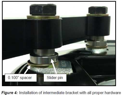
10. Install the new intermediate bracket to the original caliper mount located on the inboard side of the flange housing using the supplied M14-2.0x60 bolts, washers, spacers, and slider pins (bracket part number faces inboard). **Note: Due to system requirements and fitment, the use of 0.100” thickness spacers will be required. The spacers will rest between the flange housing and the head of the slider pin. Add extra shims as needed to center the caliper. Ensure that the dust shield does not interfere with the bracket in any way. Slide the bracket inboard followed by sliding it outboard, along the slider pins. Remove material from the dust shield if interference occurs. Tighten the bolts for now as shimming will need to occur.

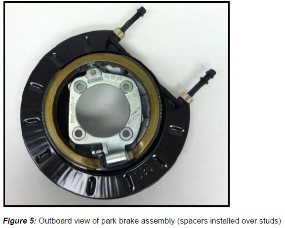
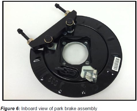
Note: The intermediate bracket will arrive pre-installed to the caliper for ease of shipping. Also, the M14-2.0x60 bolts, washers, and slider pins will come attached with this assembly, too. See Figures 4-6 for reference of install. 

11. The next step is to slide the spacers over the radial mount studs and onto the intermediate bracket. For Extreme 15” brake systems, 0.500” thick spacers are supplied (one per radial stud).  


12. Install the correct side rotor and secure with three lug nuts and washers to avoid scratching the rotor hat.
13. With the pads removed, install the correct side caliper (bleeder screws pointed up) with the ARP washers and 12 point nuts. Tighten the 12-point nuts for now as shimming will occur next.

Shimming Procedure

Measure the gap from the rotor to caliper body at 4 points, top inside and outside, bottom inside and outside. Write down all measurements. Subtract the top inside measurement from top outside. This will require a shim at the top bracket bolt equal to half of this difference to center the caliper. For instance, inside measurement of .865”, outside of .905” has a difference of .040 which would require a .020” shim installed to center. Do the same with the bottom measurements to center this also. Getting these gaps as close as possible within .005” will keep the possibility of excessive noise to a minimum. This may require different thickness shims top and bottom.
Note: The purpose for shimming is to allow the caliper to be properly centered above the rotor.
Procedure
1. Select the required shims from the kit provided
2. Pull the axle outboard until it won’t go any further (this may not move much) and slide the caliper and bracket inboard, together.
3. Obtain measurements as described above. Remove the caliper
4. Loosen the bolts from the intermediate bracket
5. Install the appropriate shims (between the flange housing and slider pins), removing one bolt at a time, and snug the same bolts for fit check
6. Reinstall the caliper and recheck gap measurements
7. Re-shim if necessary. When proper shimming has been achieved, torque the M14-2.0x60 bolts to 110 ft∙lbs. Finally, install the caliper back onto the radial studs and torque the ARP nuts to 75 ft∙lbs.
If you do not have access to a dial caliper, these measurements can be made with pads installed using a feeler gauge between the rotor and pad. Take measurements from top inside and outside, then bottom inside and outside. Minimum clearance is .010” between pad and rotor, but gaps as close to equal as possible at all four locations is best.

For vehicles with factory drum brakes, follow step 13A

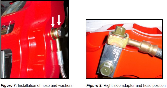
13A. Finger tighten the steel braid banjo hose end with one copper washer on each side of the  banjo fitting into the rear of the caliper. Connect the hose to the hardline at the frame and  install the hose lock. **IMPORTANT: Position the hose to avoid interference with the  wheel and suspension components through the entire range of motion. Tighten fitting  and banjo bolt to 15-20 ft∙lbs. See Figure 7 for reference, shown below. 

For vehicles with factory disc brakes, follow step 13B

13B. This system will use the original hoses to supply fluid. New copper washers are provided as  these are a one-time use item. An adaptor block is also provided to attach to the caliper. The  original hose and new banjo bolts will attach to this block. Position the adaptor block on the  caliper as in Figure 8, and secure with the supplied short banjo bolt and two copper  washers. Your original hose will attach to the adaptor block with the supplied long banjo bolt  and two copper washers. The copper washers go on each side of the banjo fitting of the  original hose. Torque both bolts between 15-20 ft∙lbs. **IMPORTANT: Ensure to route the  brake hose away from suspension and wheels to avoid any interference through full  articulation of suspension system. See Figure 8 below, for correct orientation. 

14. Repeat these steps for the other side of the vehicle and be sure to recheck all attachment  points and fittings. 


Refer to Bleeding, and Pad Bedding & Rotor Seasoning Procedures contained on a separate sheet, or on www.baer.com
For service components and replacement parts contact your Baer Brake Systems Tech Representative.

Best Sellers