 FREE 1 to 3-Day Delivery on Orders $149+ Details
How to Install Baer AlumaSport Front Brake Kit - Red (07-18 Silverado 1500) on your Chevy Silverado
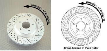
When installing rotors be sure to follow the direction of rotation indicated on the rotor hat area with either an arrow, or an “L” for left, or an “R” for right, or both. “L” or left always indicates the driver’s side of US spec vehicles. Images shown are left rotors:
INSTALLATION:
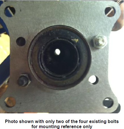
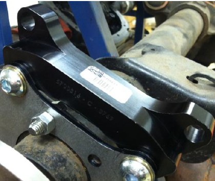
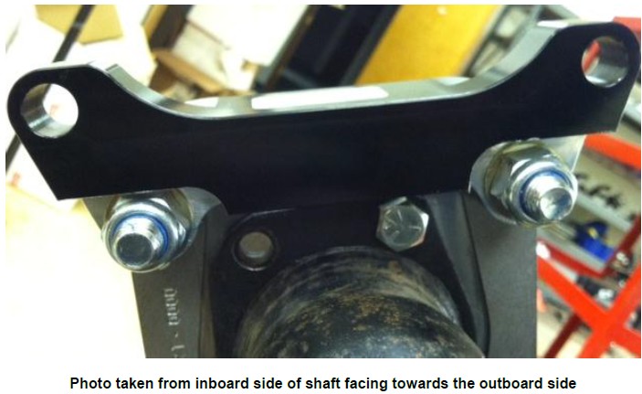
7. Next, install the intermediate bracket onto the steel plate using the supplied M12-1.75x45 button head bolts, 7/16” washers, and Nylock nuts. Place about .100” thickness of shim between both brackets so that the caliper install will be easier; more shim may need to be added. Each button head bolt will contain two washers (one on each side of the bracket). For now, simply tighten the bolts snug as more shimming will need to be completed in the latter portion of installation. **Note: The intermediate bracket will mount with the step cutout facing the inboard side of vehicle. See photos below and on continued page for reference:
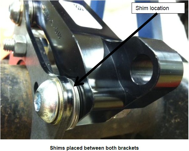
Shimming Procedure
Measure the gap from the rotor to caliper body at 4 points, top inside and outside, bottom inside and outside. Write down all measurements. Subtract the top inside measurement from top outside. This will require a shim at the top bracket bolt equal to half of this difference to center the caliper. For instance, inside measurement of .865”, outside of .905” has a difference of .040 which would require a .020” shim installed to center. Do the same with the bottom measurements to center this also. Getting these gaps as close as possible within .005” will keep the possibility of excessive noise to a minimum. This may require different thickness shims top and bottom.


