 FREE 1 to 3-Day Delivery on Orders $149+ Details
How to Install Air Lift Performance SlamAir Adjustable Air Springs for 4-6 in. Drop (07-18 Sierra 1500) on your GMC Sierra
Installation Time
2 hours
Tools Required
- Hoist or floor jacks
- Safety stands
- Safety glasses
- Torque wrench
- Ratchet w/ 3/8”, 9/16”, & 1/2” deep well sockets
- 3/8” and 9/16” Drill bit (very sharp)
- 3/8” Nut driver
- 1/2”, 3/4”, 7/16”, and 1-1/16” open-end or box wrenches
- Heavy duty drill
- Hose cutter, razor blade, or sharp knife
- Air compressor or compressed air source
- Spray bottle with dish soap/water solution
Introduction
The purpose of this publication is to assist with the installation, maintenance and troubleshooting of the SlamAir air spring kit. It is important to read and understand the entire installation guide before beginning installation or performing any maintenance, service or repair. The information here includes a hardware list, tool list, step-by-step installation information, maintenance tips, safety information and a troubleshooting guide. Air Lift Company reserves the right to make changes and improvements to its products and publications at any time. For the latest version of this manual, contact Air Lift Company at (800) 248-0892 or visit our website at www.airliftcompany.com. IMPORTANT SAFETY NOTICE The installation of this kit does not alter the Gross Vehicle Weight Rating (GVWR) or payload of the vehicle. Check your vehicle’s owner’s manual and do not exceed the maximum load listed for your vehicle. Gross Vehicle Weight Rating: The maximum allowable weight of the fully loaded vehicle (including passengers and cargo). This number — along with other weight limits, as well as tire, rim size and inflation pressure data — is shown on the vehicle’s Safety Compliance Certification Label. Payload: The combined, maximum allowable weight of cargo and passengers that the truck is designed to carry. Payload is GVWR minus the Base Curb Weight. NOTATION EXPLANATION Hazard notations appear in various locations in this publication. Information which is highlighted by one of these notations must be observed to help minimize risk of personal injury or possible improper installation which may render the vehicle unsafe. Notes are used to help emphasize areas of procedural importance and provide helpful suggestions. The following definitions explain the use of these notations as they appear throughout this guide.
Installation Diagram
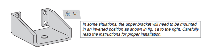
Figure 1b
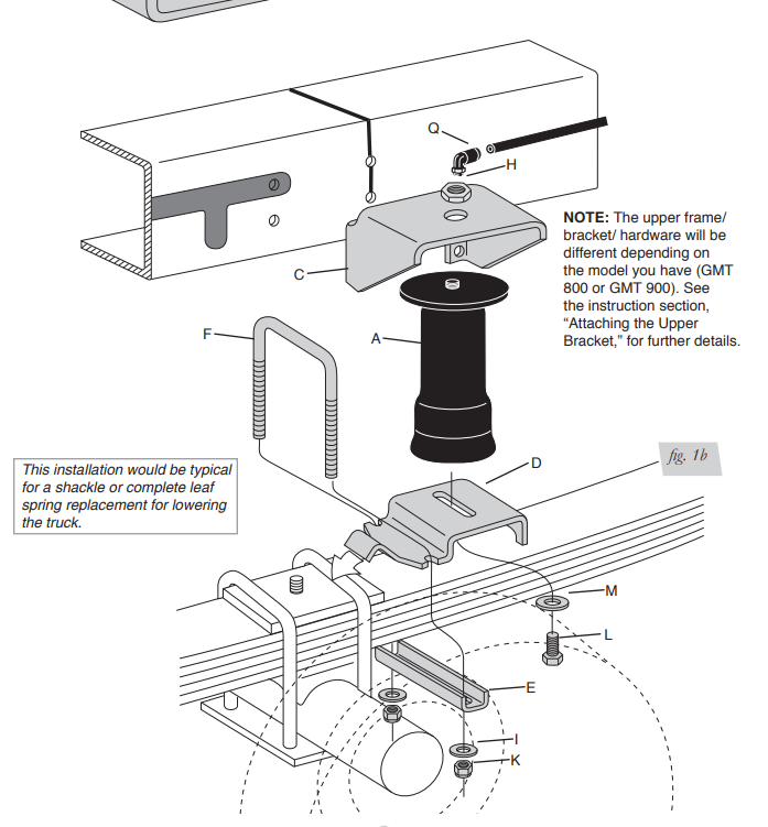
Figure 2A
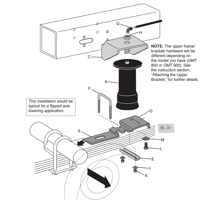
Figure 2b
Installing the SlamAir System
IMPORTANT INSTALLATION INFORMATION IMPORTANT: Your vehicle may be equipped with a rear brake proportioning valve. Any type of load assist product could affect brake performance. Air Lift recommends checking with your dealer before installing this type of product. if your vehicle DOES NOT have a rear brake proportioning valve or is equipped with an anti-lock type brake system, installation of the load assist product will have NO AFFECT on brake system performance. COMPRESSED AIR CAN CAUSE INJURY AND DAMAGE TO THE VEHICLE AND PARTS IF IT IS NOT HANDLED PROPERLY. FOR YOUR SAFETY, DO NOT TRY TO INFLATE THE AIR SPRINGS UNTIL THEY HAVE BEEN PROPERLY SECURED TO THE VEHICLE. This is a universal kit for custom applications. In no way should the air spring or any of the kit’s components be the suspension limiter in compression or extension. This air spring can compress to 2.4” and extend to 7.0”. Regardless of load, the air pressure should be adjusted so that the custom ride height is maintained at all times. The shock absorber is usually the limiter on extension. If this is not the case, you should consider the use of limiting straps.
GETTING STARTED
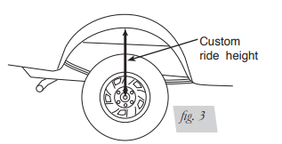
1. Determine the custom ride height of the lowered vehicle. The custom ride height is the distance between the bottom edge of the wheel-well and the center of the hub when the vehicle is in the custom, lowered condition (fig. 3). In some cases, the ride height is not perfectly level.
a. Remove unusual loads and examine the vehicle from the side to ensure it is on a level surface.
b. If necessary—in cases where your leaf springs are sagging badly—use a jack to raise the rear end so that the vehicle achieves the custom, lowered ride height.
Figure 3
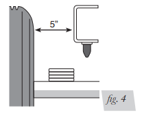
2. Measure the distance between the frame and the tire. This kit requires a minimum of 5” of clearance for a fully inflated air spring (fig. 4).
Figure 4
RAISING THE VEHICLE
1. Raise the vehicle and remove the wheels
2. Ensure that the vehicle is at the custom, lowered ride height. If not, raise the frame or lower the axle as necessary.
a. If the vehicle is raised with an axle contact hoist, place axle stands under the frame and lower the axle as needed.
b. If the vehicle is raised with a frame contact hoist, place axle stands under the axle and lower the frame as needed.
c. If the vehicle is raised with a jack and supported with axle stands on the frame, use a floor jack to raise the axle.
DECIDING WHERE TO MOUNT
Due to the wide variety of lowering kits on the market, Air Lift cannot guarantee that this kit will fit every vehicle. You may need to modify the upper bracket, or even weld it, depending on the type of kit the vehicle was lowered with or optional equipment present. Where you install the air spring kit will depend on the type of vehicle you have and the placement necessary to avoid brake lines, gas lines, hydraulic lines or other items that may interfere with drilling the upper bracket holes. Some situations, such as vehicles with staggered shock absorbers, may require installing the air springs in front and behind the axle on opposite sides of the vehicle. Where applicable, pay attention to specific instructions on the placement of the air spring for your model noted. The installation tool included in this kit will help check for obstacles and determine which installation is best for your vehicle. On some models it may be necssary to invert the upper bracket in a “legs up” position to achieve the correct mounting position. Do not hang the axle on a frame contact hoist while checking this step for proper placement of the upper bracket. Vehcile suspension must be in custom ride height condition.
ASSEMBLING THE INSTALLATION TOOL
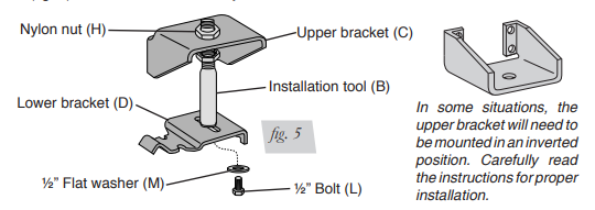
1. The tool provided with this kit will assist in proper setup and alignment of the air spring and will also position the upper bracket for drilling the bolt holes. The tool attaches to the upper and lower bracket and is rigid so that it will self-align the upper bracket. The threaded section of the upper part of the tool ensures that the air spring can only be mounted at the correct height.
2. Secure the upper bracket (C) to the installation tool (B) using the provided nylon nut (H) (fig. 5).
NOTE: As stated above, it may be necessary to invert the upper bracket based on the type of drop installed.
3. Loosely attach the tool to the lower bracket using a ½” flat washer (M) and a ½” bolt (L) (fig. 5). Leave loose for later adjustment.
Figure 5
INSTALLING THE L-BRACKETS (For flipped axle lowered applications)
1. Support the frame and drop the rear axle all the way until the axle is hanging. If the shock stops the axle from hanging, remove the lower shock bolts.
2. Remove the leaf spring retaining u-bolts on one side and, with a floor jack, raise the axle to clear the leaf spring centering pin.
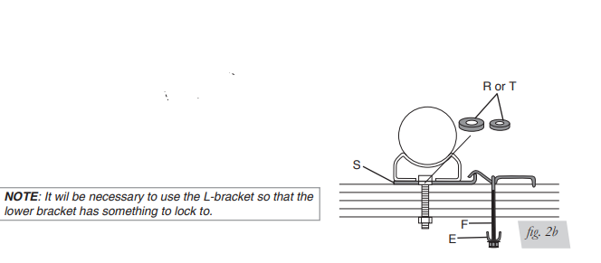
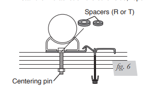
3. A spacer is provided to accommodate the increased thickness caused by the lower bracket. Clamp the leaf spring together with a c-clamp so the leaf center pin can be removed. Remove the centering pin and install one spacer, per pin (see fig. 6).
Note: There are two different size spacers (R or T). Use the spacer that fits and discard the other.
Figure 6
4. Reinstall the centering pin. If the nut does not have full thread contact, replace the centering pin.
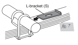
5. GMT 800 (1999 to 2007) classic models mount forward of the axle. GMT 900 (2007 and later) models mount behind the axle.
6. Set the L-bracket (S) on the leaf, making sure the centering pin goes through the slot on the L-bracket. Drop the axle down, and reinstall the u-bolts. Slightly tighten the u-bolts so that the lower bracket can be adjusted later (fig. 7)
Figure 7
ATTACHING THE LOWER BRACKET
1. Set the installation tool assembly on the leaf spring.
Note: GMT 800 (1999 to 2007) classic models mount forward of the axle. GMT 900 (2007 and later) models mount behind the axle.
2. Place the hook end of the lower bracket (D) over the stock U-bolt or the edge of the L-bracket (for flipped axle lowering kits) (fig. 1 or 2).
Note: This is important so that the lower bracket does not “walk” up the leaf spring.
3. Attach the lower bracket to the leaf spring with the supplied U-bolt (F), lower clamp bar (E), 3/8” flat washers (I) and nyloc nuts (K). Torque to 16 ft/lbs.
Note: The bracket will pull down flat to the leaf spring when the nuts are tightened.
POSITIONING THE UPPER BRACKET
Note: See the special instructions for Sierra/Silverado GMT 800 and GMT 900 on page 8 and 9 before proceeding with installation.
Note: Vehicle must be at custom ride height
1. Using the slot in the lower bracket (D), push the upper bracket (C) against the frame rail.
2. Use the pal nut on the threaded portion of the installation tool and a supplied nylon nut to adjust the upper bracket so that the upper bracket legs are flat against the frame rail and all four holes are in the middle section of the frame. The mounting holes must stay 3/4” from the rounded edges of the frame rail and AT LEAST 1.25” must be left above the top of the upper bracket for air fitting clearance ( see Special Instructions on GMT 900 Installation). The brackets can be mounted anywhere within the threaded range of the installation tool.
Note: On some models it may be necessary to invert the upper bracket in a “legs up” position to achieve the correct mounting position (fig. 1 or 2).
ATTACHING THE UPPER BRACKET
IMPORTANT: Please read this entire section before drilling any holes. BEFORE DRILLING, CHECK THE BACK SIDE OF THE FRAME FOR CLEARANCE ISSUES SUCH AS BRAKE LINES, GAS LINES, ELECTRICAL LINES, ETC. ALL OBSTACLES NEED TO BE TEMPORARILY RELOCATED TO CLEAR THE AREA.
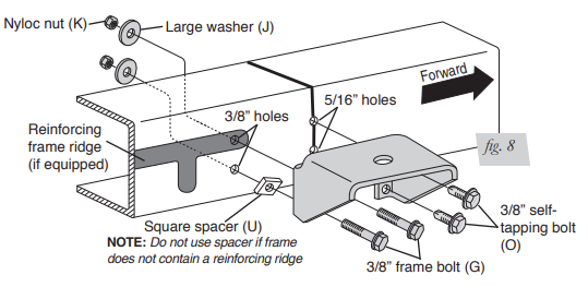
1999-2007 GMT 800 Silverado/Sierra Classic Models
1. Adjust the upper bracket along the installation tool until the upper rearward hole lines up squarely on the ridge (fig. 8).
Figure 8
2007 & Later GMT 900 Silverado/Sierra Models
1. Position the upper bracket using the threaded portion of the tool so that the top, forward mounting hole is slightly above the large slot in the side of the frame (fig. 9).
Note: Maintain a distance of 1.25” above the upper bracket for valve clearance. If needed, it may be necessary to bend the flange on the inner wheel well seam to obtain this clearance
2. Using the upper bracket as a template, drill 3/8” holes through the frame for the mounting hardware (fig. 9).
Note: For clearance when drilling the frame, it may be necessary to unbolt and move the brake line bracket on the driver side.
Figure 9
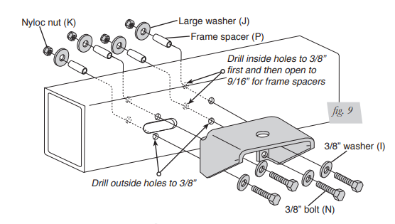
4. Remove the installation tool and attach the upper brackets (fig. 9):
- Attach a flat washer (I) to the long 3/8” bolt (N).
- Insert the bolt through the upper bracket, into and through the inside of the frame.
- Insert the frame spacer (P) over the long bolt, into the frame (from the inside).
- Cap with a large flat washer (J) and nyloc nut (K).
- Repeat for all four bolts. Tighten securely. - Reattach the brake line bracket if previously removed.
MOUNTING THE AIR SPRING
1. Install the air fitting into the top of the air spring. Tighten with fingers and then seal the fitting by tightening one and a half turns with an 7/16” open-end wrench, being careful to tighten on the metal hex nut only. IMPORTANT: Do not overtighten.
Note: This swivel air fitting is precoated with a sealant
2. Collapse the air spring and guide the fitting through the center mounting hole in the upper bracket.
3. Install the nylon nut (H) onto the upper threadpost of the air spring. Leave loose for final adjustment.
4. Attach the air spring to the lower bracket. Carefully hold the lower mounting bolt with a 3/4” open end wrench and hand turn the air spring onto the lower mounting bolt. Important: Leave loose for later adjustment.
5. Tighten the nylon nut to 4 ft/lbs. IMPORTANT: Do not overtighten.
INSTALLING THE AIR LINES
1. Choose a convenient location for mounting the inflation valves. Popular locations for the inflation valve are:
a. The wheel well flanges.
b. License plate recess in bumper.
c. Under the gas cap access door.
d. Through license plate itself.
Note:What ever the chosen location is, make sure there is enough clearance around the inflation valves for an air chuck.
2. Drill a 5/16” hole to install the inflation valves.
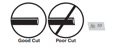
3. Cut the air line assembly (AA) in two equal lengths.
Caution: WHEN CUTTING OR TRIMMING THE AIR LINE, USE A HOSE CUTTER, A RAZOR BLADE OR A SHARP KNIFE. A CLEAN, SQUARE CUT WILL ENSURE AGAINST LEAKS. DO NOT USE WIRE CUTTERS OR SCISSORS TO CUT THE AIR LINE. THESE TOOLS MAY FLATTEN OR CRIMP THE AIR LINE, CAUSING IT TO LEAK AROUND THE O-RING SEAL INSIDE THE ELBOW FITTING (FIG. 10)
Figure 10
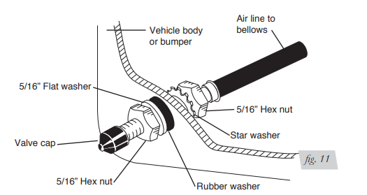
4. Place a 5/16” nut (GG) and a star washer (FF) on the air valve. Leave enough of the inflation valve in front of the nut to extend through the hole and have room for the rubber washer (EE), flat washer (DD), and 5/16” nut (GG) and cap (CC). There should be enough valve exposed after installation - approximately 1/2” - to easily apply a pressure gauge or an air chuck (fig. 11).
5. Push the inflation valve through the hole and use the rubber washer (EE), flat washer (DD), and another 5/16” nut (GG). Tighten the nuts to secure the assembly in place (fig. 11)
Figure 11
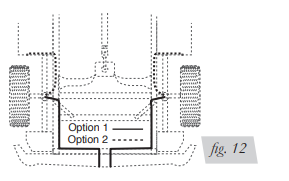
6. Route the air line along the frame to the air fitting on the air spring (fig. 12). Keep AT LEAST 6” of clearance between the air line and heat sources, such as the exhaust pipes, muffler, or catalytic converter. Avoid sharp bends and edges. Use the plastic tie straps (BB) to secure the air line to fixed, non-moving points along the chassis. Be sure that the tie straps are tight, but do not pinch the air line. Leave at least 2” of slack to allow for any movement that might pull on the air line.
Figure 12
7. Cut off air line leaving approximately 12” of extra air line. A clean square cut will ensure against leaks (see fig. 10). Insert the air line into the air fitting. This is a push to connect fitting. Simply push the air line into the 90° swivel fitting until it bottoms out (9/16” of air line should be in the fitting).
ALIGNING THE AIR SPRING
IMPORTANT: With the bottom of the air spring still loose, inflate the air spring to approximately 10 PSI.
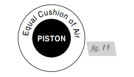
1. Use the slotted adjustment in the lower bracket to correctly align the air spring between the upper and lower brackets. This can be accomplished by tapping it inboard (towards the vehicle) or outboard (towards the wheel) for proper alignment. There should be a symmetrical cushion of air around the base of the air spirng when correctly positioned. (fig. 13).
Figure 13
2. If the L-brackets were installed (flipped application installation), torque the u-bolts to OEM specifications.
3. Repeat on the other side of the vehicle.
CHECKING FOR LEAKS
1. Inflate the air spring to 30 PSI and spray all connections and the inflation valves with a solution of 1/5 liquid dish soap and 4/5 water to check for leaks. Spot leaks easily by looking for bubbles in the soapy water.
2. After the test, deflate the springs to the minimum pressure required to restore the custom ride height, no less than 10 PSI.
3. Check the air pressure again after 24 hours. A 2-4 PSI. loss after initial installation is normal. Retest for leaks if the loss is more than 5 lbs.
FIXING LEAKS
1. If there is a problem with the swivel fitting:
a. Check the air line connection by deflating the spring and removing the line by pulling the collar against the fitting and pulling firmly on the air line. Trim 1” off the end of the air line. Be sure the cut is clean and square (see fig. 10). Reinsert the air line into the push-to-connect fitting.
b. Check the threaded connection by tightening the swivel fitting another ½ turn. If it still leaks, deflate the air spring, remove the fitting, and re-coat the threads with thread sealant. Reinstall by hand tightening as much as possible, then use a wrench for an additional two turns.
2. If there is a problem with the inflation valve, then: a. Check the valve core by tightening it with a valve core tool. b. Check the air line connection by removing the air line from the barbed type fitting.
Caution: DO NOT CUT THE AIR LINE COMPLETELY OFF AS THIS WILL NICK THE BARB AND RENDER THE FITTING USELESS.
3. If the preceding steps have not resolved the problem, call Air Lift customer service at (800) 248-0892 for assistance.


