FREE 1 to 3-Day Delivery on Orders $149+ Details
How to Install Wilwood Tactical Xtreme TX6R Front Brake Kit - Black on your F-150

Shop Parts in this Guide
•Installation of this kit should ONLY be performed by persons experienced in the installation and proper operation of disc brake systems. Before assembling this Wilwood disc brake kit, double check the following to ensure a trouble free installation. • Inspect the contents of this kit against the parts list to ensure that all components and hardware are included. • Make sure this is the correct kit to fit the exact make and model year of your vehicle. This kit is designed for direct bolt-on installation to 2010-present model year Ford F-150 Series Trucks with 6 lug hubs. • Verify your wheel clearance using Figure 2. • Verify that the factory axle hub center register diameter and lug pattern match those in the new hat. NOTE: Axle hubs that have been modified with different size studs or lug patterns may require modifications to the new hat that must be performed by a qualified machinist. Disassembly • Disassemble the original equipment front brakes: Raise the front wheels off the ground and support the front suspension according to the vehicle manufacturer’s instructions. Remove the front wheels, calipers, rotors, and dust shield. •Remove any nicks or burrs on the axle hub and upright that may interfere with the installation of the new brake components. •Clean and de-grease the axle hub and upright assembly
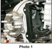
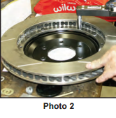
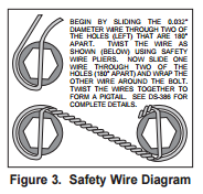
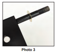
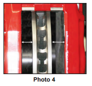
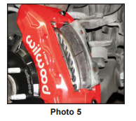
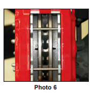
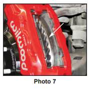
Assembly Instructions (numbers in parenthesis refer to the parts list and Figure 1 on the preceding pages): • The caliper mount bracket (1) should initially be installed with clean, dry threads on the mounting bolts. Orient the bracket as shown in Figure 1 and Photo 1, and install using bolts (2) and washers (3). Initially place one .024 thick shim (4) on each bolt between the bracket and upright, Figure 1. Temporarily tighten the mounting bolts. NOTE: The bracket must fit squarely against the mount bosses on the upright. Inspect for interference from casting irregularities, machining ridges, burrs, etc. Later, after the caliper alignment has been checked, the mount bolts will be secured using red Loctite® 271. • Orient the rotor (5) and the hat (6) as shown in Figure 1 and Photo 2. Attach rotor to hat using bolts (7) and washers (8). Using an alternating sequence, torque to 25 ft-lbs. For an added measure of security, the bolts may be safety wired using standard 0.032 inch diameter stainless steel safety wire as shown in Figure 3. Refer to Wilwood’s data sheet DS-386 (available at www.wilwood.com/Pdf/DataSheets/ds386.pdf) for complete safety wire installation instructions. • Slide the hat/rotor assembly onto the axle hub. NOTE: The hat must fit flush against the axle hub flange or excessive rotor run out may result. Install three lug nuts (finger tight) to keep the hat/rotor assembly in place while continuing with the installation. •NOTE: This kit contains distinct right and left hand calipers that must be mounted in a specific direction, as described below. Lubricate the caliper mounting studs (12) with lightweight oil. Initially place one .032” thick shim (13) on each stud as shown in Figure 1 and Photo 3. Mount the caliper (9) onto the bracket (1) using lock nuts (10) and washers (11), Figure 1. Ensure that the caliper is mounted so that the largest pistons are at the rotor exit end of the caliper, in relation to the direction of rotor rotation. Temporarily tighten the lock nuts and view the rotor through the top opening of the caliper. The rotor should be centered in the caliper, Photo 4. If not, adjust by adding or subtracting shims (4) between the bracket and the upright. Always use the same amount of shims on each of the two mounting bolts. Once the caliper alignment is correct, remove the bracket mounting bolts (2) one at a time, apply red Loctite® 271 to the threads, and torque to 120 ft-lb. • Remove the two pad retaining pins from the caliper by carefully popping out the pin retaining clips and sliding out the pins. Insert the brake pads (14) into the caliper, with the friction material facing the rotor, as shown in Photo 5 and secure the brake pads in place with the pad retaining pins and clips, Photo 6. Check that the top of the brake pad is flush with the outside diameter of the rotor, Photo 7. If not, adjust by adding or subtracting shims (13) between the caliper and the bracket. After the caliper pad height is set, torque the caliper lock nuts (10) to 65 ft-lb. • Temporarily install the wheel and torque the lug nuts to the manufacturer’s specification. Ensure that the wheel rotates freely without any interference.
•NOTE: OEM rubber brake hoses generally cannot be adapted to Wilwood calipers. The caliper inlet fitting is a 1/8-27 NPT. Wilwood offers two stainless steel braided flexline hose kits, P/N 220-12862 (2013-2014) and 220-15263 (2015-present), which includes hoses, fittings, etc. all in one package for this application. Carefully route hoses to prevent contact with moving suspension, brake or wheel components. NOTE: Wilwood hose kits are designed for use in many different vehicle applications and it is the installer's responsibility to properly route and ensure adequate clearance and retention for brake hose components. •NOTE: Specified brake hose kits may not work with all Years, Makes and Models of vehicle that this brake kit is applicable to, due to possible OEM manufacturing changes during a production vehicle's life. It is the installer's responsibility to ensure that all fittings and hoses are the correct size and length, to ensure proper sealing and that they will not be subject to crimping, strain and abrasion from vibration or interference with suspension components, brake rotor or wheel. •In absence of specific instructions for brake line routing, the installer must use his best professional judgment on correct routing and retention of lines to ensure safe operation. Test vehicle brake system per the 'minimum test' procedure stated within this document before driving. After road testing, inspect for leaks and interference. Initially after install and testing, perform frequent checks of the vehicle brake system and lines before driving, to confirm that there is no undue wear or interference not apparent from the initial test. Afterwards, perform periodic inspections for function, leaks and wear in a interval relative to the usage of vehicle. • Bleed the brake system, referring to the additional information and recommendations below for proper bleeding instructions. Check system for leaks after bleeding. •Install the wheel and torque the lug nuts to manufacturer’s specification