 FREE 1 to 3-Day Delivery on Orders $149+ Details
How to Install Wilco Offroad Hi-Lift Jack Vertical Mount Tire Carrier & Plastic Jerry Can Mounting Kit (97-18 All) on your Ford F-150
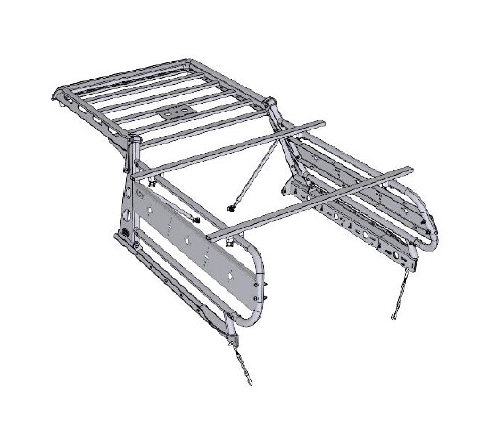
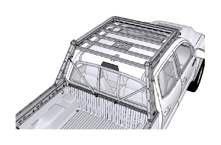
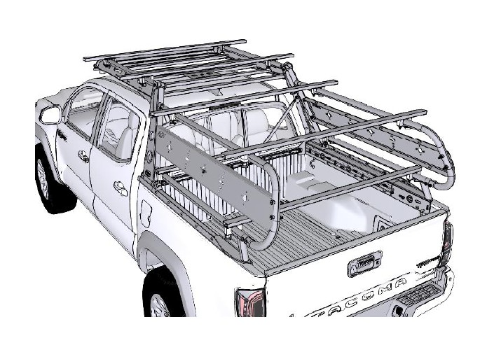
This guide will show you how to install your new Wilco Off-road ADV Trail Boss Complete Kit.
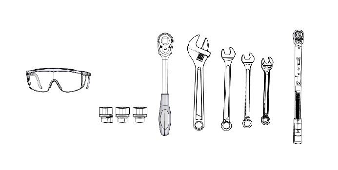
To complete this installation, you will need the following tools. 10, 15, 17, and 19 millimeter Box Wrenches, Adjustable Wrench, Socket Wrench with 10, 15, 17 and 19 millimeter Sockets, Safety glasses and a Torque Wrench. It is recommended that you lay out all the parts and tools prior to beginning.
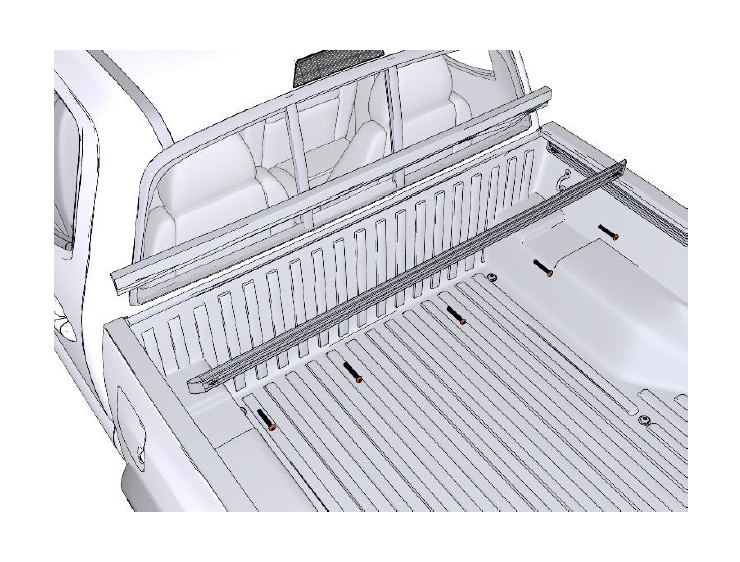
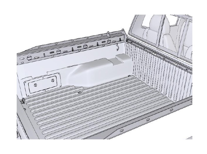
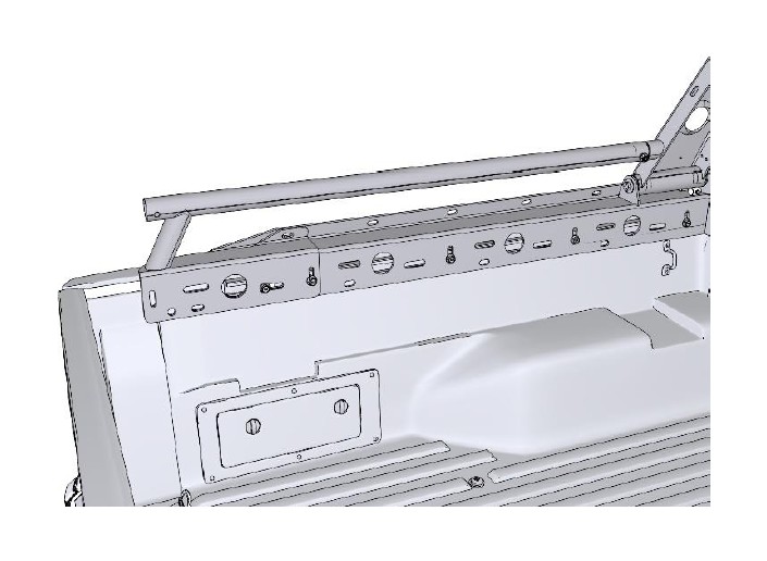
Unscrew the (5) M10 by 60 Button Screws and remove the factory Bed Cross Member. Attach the Bed Rail with the screws you just removed.
Remove the factory Bed Rail End Caps and set them aside.
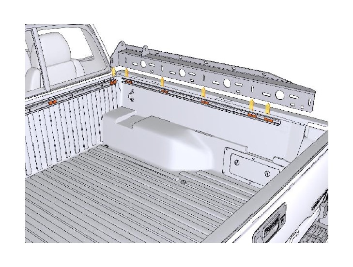
Place (5) Bedrail Clamp Plates in the passenger side Bed Rail, (5) in the driver side Bed Rail, and (4) in the forward, or cab, Bed Rail. Place the Passenger Bedrail Weldment onto the bed and align it with the Bedrail Clamp Plates.
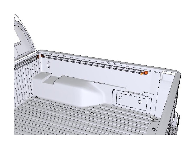
Using a Socket Wrench, (3) M10 by 25 Bolts and an M10 by 35 Bolt attach the Bedrail Weldment as shown. Torque the bolts to 45 foot-pounds.
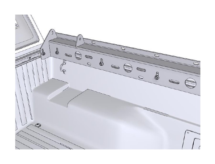
Attach the Driver Bedrail Weldment as shown and torque the bolts to 45 foot-pounds.
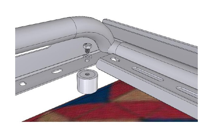
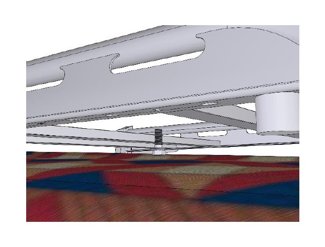
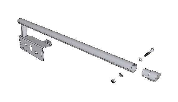
Place a Rack Adjustment Assembly on the Driver Bedrail Weldment as close to the cab as you can, making sure the screw head is accessible. Now place the Driver Riser Weldment onto the Rack Adjustment Assembly.
Insert a Half by 13 by 12 Bolt, (2) Half Inch Washers, and a Half Inch Nut. Tighten the nut down only slightly. This will be torqued in a later step.
Screw the Rack Adjustment Assembly clockwise to adjust upwards, and counter-clockwise to adjust downwards.
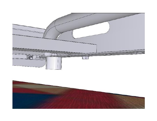
Install the Rack Adjustment Assembly on the passenger side, and the Passenger Riser Weldment. Do not fully tighten at this point.
Attach the passenger side Corner Brace by first mounting it to the cab Bedrail Clamp Plate and then to the Passenger Side Riser Weldment. Do not fully tighten the nuts and bolts at this point.
Attach the driver side Corner Brace the same way. Do not fully tighten the nuts and bolts at this point.
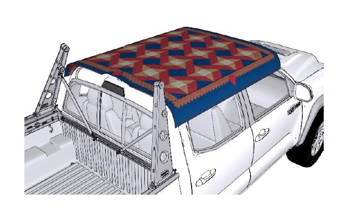
You may want to place a Blanket or some other protective cover over the roof of your truck to prevent any damage.
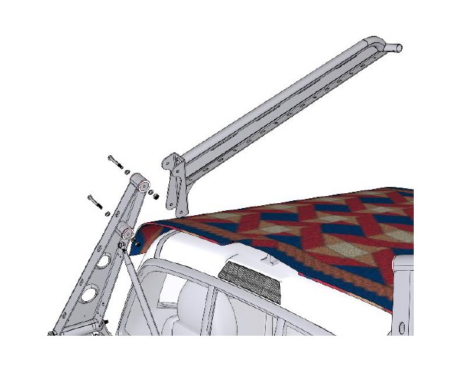
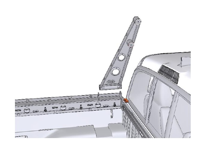
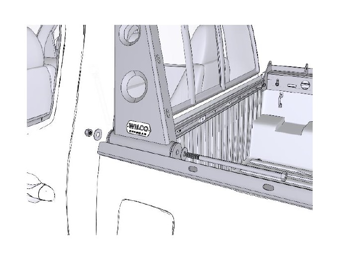
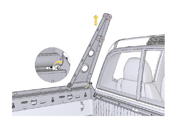
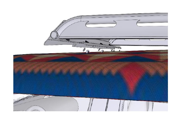
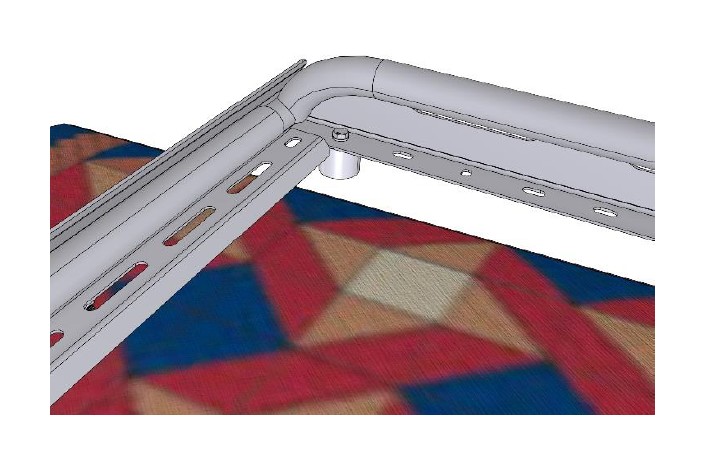
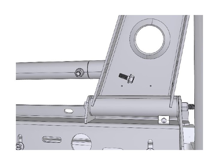
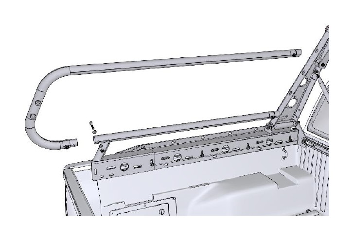
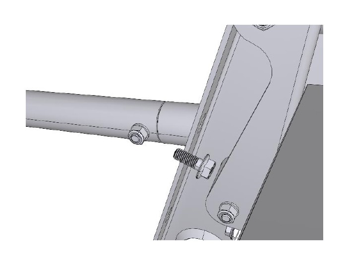
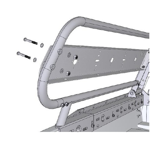
Place the Driver Side Frame Weldment to the Driver Side Riser Weldment. Attach the top M10 by 1.5 by 90 Hex Screw, M10 Washers and M10 Lock Nut first. Next, attach the lower bolt, washers and nut. Do not fully tighten the nuts at this point.
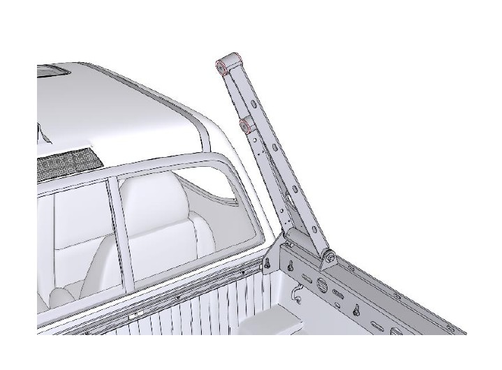
Attach the Passenger Side Frame Weldment to the Passenger Side Riser Weldment the same way. Insert the top bolt and washers first, and then the lower bolt and washers. Do not fully tighten the nuts at this point.
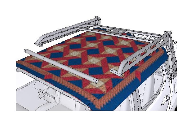
Place the Tire Support Rack between the Frame Weldments as it will not fit once they are connected. Place the Horizontal Connecting Tube over each of the Frame Weldments. There should be enough play in each of the Riser Weldments and Frame Weldments to fit the Horizontal Connecting Tube with ease.
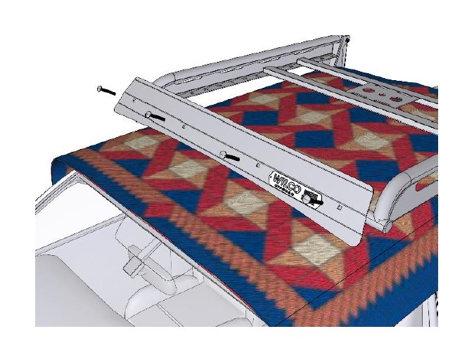
Place the Fairing onto the Horizontal Connecting Tube and insert the (4) Carriage Bolts.
Place the Light and Hooking Bracket to the underside of the Horizontal Connecting Tube ensuring the correct orientation. Attach the brackets using (4) M10 Lock Nuts and M10 Washers.
Attach the Bumper to the Driver Side Frame Weldment.
Attach the Bumper to the Passenger Side Frame Weldment.
Slide the Racking Tube into position on the foremost holes on the Frame Weldments.
Attach the Racking tube using an M10 by 25 Bolt.
Attach the other side of the Racking tube using an M10 by 25 Bolt.
Install the remaining Rack Tubes using the same method and hardware. Install the Tire Support Rack in the same way. You may now remove the protective Blanket.
Attach the Angle Plugs to the Driver side and Passenger Side Lowrider Weldment.
Place the Driver Side Lowrider Weldment onto the Driver Bedrail Weldment and Driver Riser Weldment. Attach to the Bedrail Weldment with (2) M10 by 35 Bolts. Do the same on the Passenger Side Lowrider Weldment.
Attach the Driver Side Lowrider Weldment to the Driver Side Riser Weldment using an M10 by 25 Bolt. Do the same on the Passenger Side Riser Weldment.
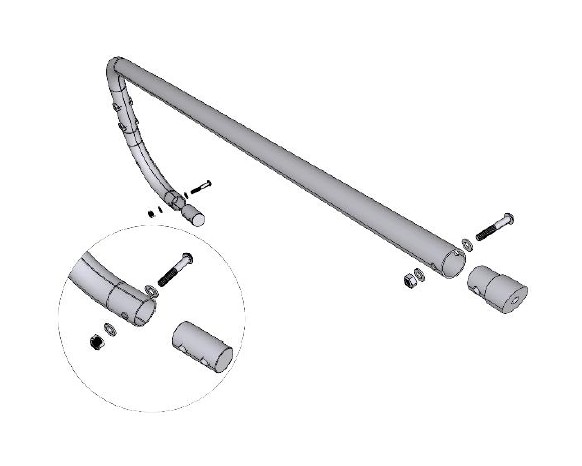
Assemble both Highrider Tubes by attaching Angle Plugs to the end of the straight tube. Then, attach Straight Plugs to the curved tube.
Place a Highrider Tube assembly onto the Driver Side Lowrider Weldment and the Driver Side Riser Weldment. Attach it to the Lowrider Weldment using an M10 by 60 Screw, (2) M10 Washers and an M10 Lock Nut. Do the same for the Passenger Side Lowrider Weldment.
Attach the Highrider Tube to the Driver Riser Weldment using an M10 by 25 Bolt. Do the same for the Passenger Side Riser Weldment.
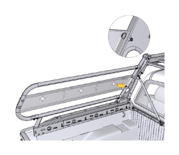
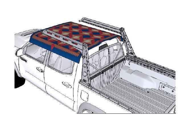
Place the Driver Expedition Panel between the Driver Side Riser Weldment and the Driver Side Highrider Tube. Attach to the Riser Weldment using (2) M10 by 1.5 by 30 Screw, an M10 Washer and an M10 Lock Nut. Do the same for the Passenger Side Expedition Panel.
Attach the Expedition Panels to the Highrider Tubes using (2) M10 by 80 Screws, (4) M10 Washers and (2) M10 Lock Nuts.
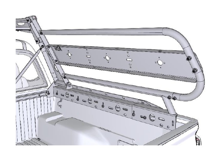
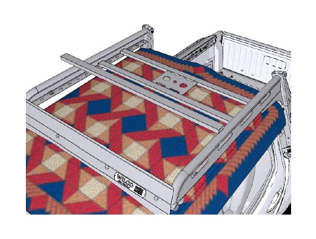
The passenger's side should be completed along with the driver's side
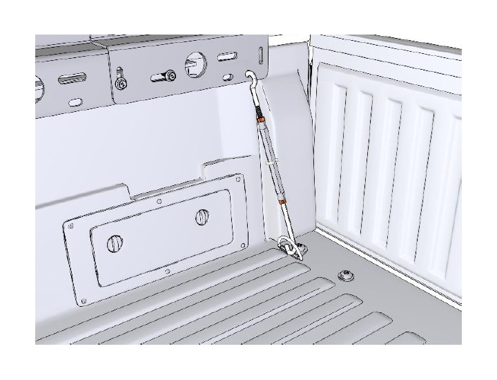
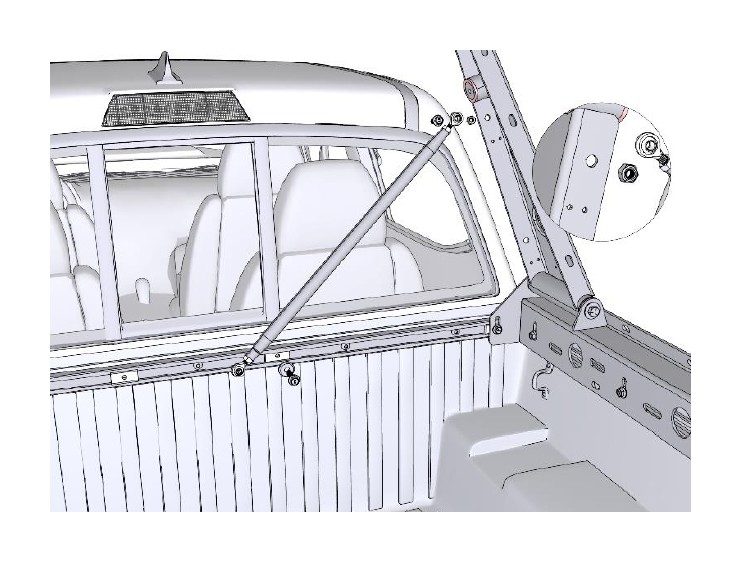
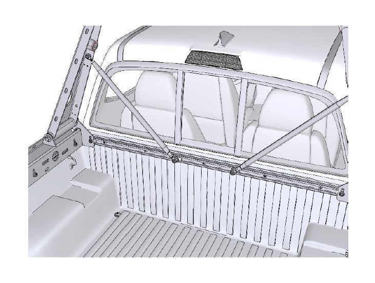
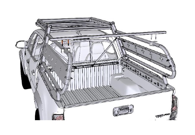
Hook one of the Turnbuckles into the hole on the Passenger Bedrail Weldment as shown. Adjust the Turnbuckle by turning the body of the Turnbuckle. Once set with moderate pressure on the D hook of the truck bed, tighten both Jam Nuts on the Turnbuckle.
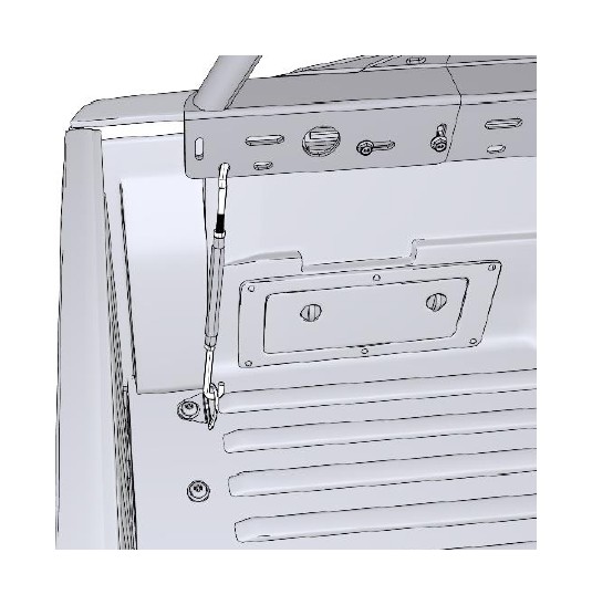
Place the Turnbuckle on the Driver Bedrail Weldment in the same way.
There are numerous locations to mount the Racking Tubes onto your ADV Trail Boss Complete Kit.
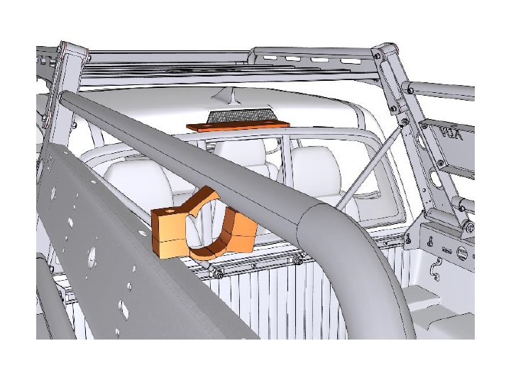
To attach the Racking Tubes, first place a Crossbar Clamp Assembly onto a Tube as shown.
Insert the Clamp bolts into the Racking tubes end and slide them inward. Position the Clamp Bolts back into the Crossbar Clamp Assembly and set it down. Ensure that the Racking Tube is centered side to side.
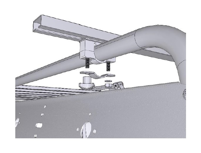
Attach the mounting hardware to the Crossbar Clamp Assembly. Tighten down when Racking Tubes are in the desired positions.
Add other Racking Tubes if applicable.
Make sure that the rack is straight and everything is properly placed. Check all the connections to make sure everything is tight. Torque the remaining bolts in order:
Riser Bolts/Nuts: 80 foot-pounds.
Corner Braces: 45 foot-pounds.
Crosstube, Rear: 45 foot-pounds.
Clamp Blocks: 35 foot-pounds.
Crosstube, Front: 40 foot-pounds.
Racking Tubes: 40 foot-pounds.
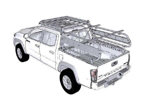
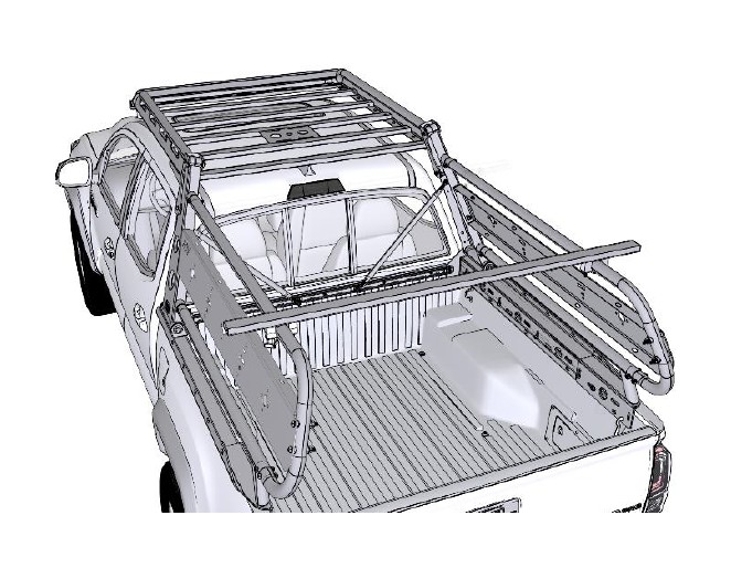
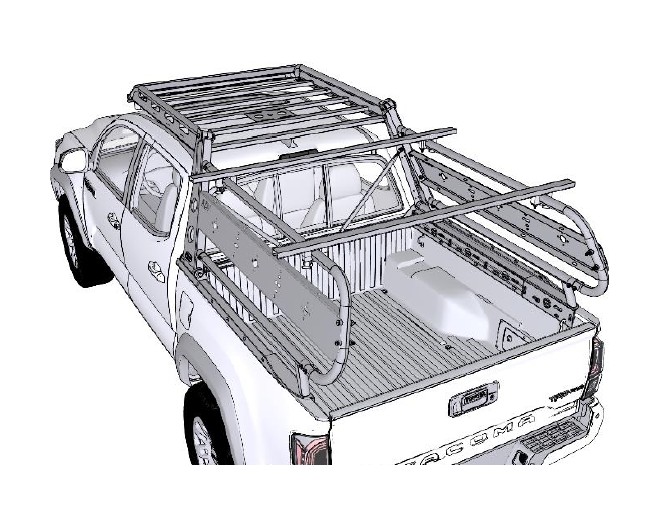
Your new Wilco Off-road ADV Trail Boss
Complete Kit is now ready for adventure!

