 FREE 1 to 3-Day Delivery on Orders $149+ Details
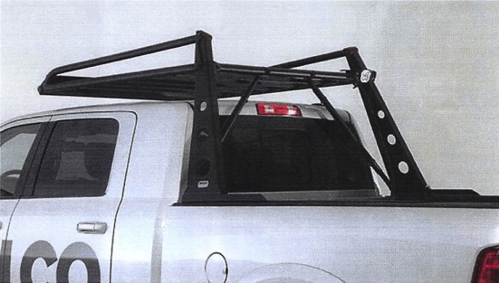
How to Install Wilco Offroad ADV Rack System on your F-150
Installation Time
3 hours
Tools Required
- Safety Glasses
- 14mm wrench
- 17mm socket
- 17mm wrench
- 19mm socket
- 1/2" wrench
- 1/2" socket wrench
- Crescent wrench
- Tin snips or heavy duty scissors
ADV RACK:
Please Read Before Install:
- Standard install time: 2-3 hours
- Recommended to use two people for install
- Weighs approximately 150 lbs
- Review torque chart
- Recommended to apply anti-seize lubricant to bolts
- Lay out tools
- Clean working environment
- Wear proper safety gear
Installation Instructions:
Step 1: To prepare for the install, lay out all the tools and hardware needed. Figure 1 and 2 shows a good example of laying out the parts and hardware.
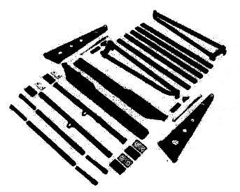
Figure 1: The parts needed for assembling the ADV Rack
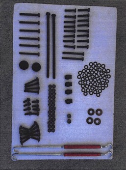
Figure 2: The hardware needed for the install
Step 2: To begin the install, access the driver and passenger side bed rails. Also grab the roll of supplied adhesive-backed rubber tape.
Step 3: Before the install of the tape make sure you know the area where it needs to be applied. The tape goes on the inside portion of the bed rails. The surface will be the side that is just solid metal with no holes in it. The tape is going to be used to protect the bed rails of the vehicle.
Step 4: To install the tape peel back the wax paper one inch and lay the tape down onto the bed rails. Put the tape down on the straight side of the rail and finish the tape on the curved side. Figure 3 shows the tape being laid down onto the bed rail.
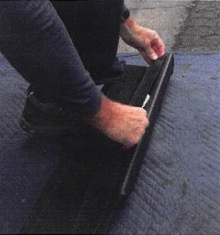
Figure 3: Laying the tape down onto the bed rail
Step 5: To finish installing the tape simply roll it out onto the bed rail. Try to keep the tape in the center portion of the rail. When you reach the other end let the tape hang over about an inch past the rail. Figure 4 shows the method of rolling the tape out on the rails.
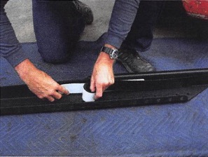
Figure 4: Rolling the tape onto the rails
Step 6: To cut the tape use tin snips or industrail scissors. Cut along the curved edge of the bed rail. Figure 5 shows the tape getting cut using the tin snips.
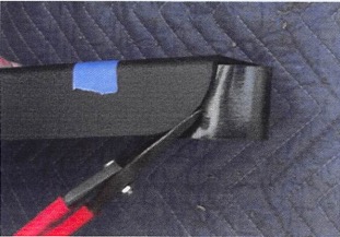
Figure 5: The tin snips cutting the tape along the edge of the rail.
Step 7: Repeat steps 4-6 for the other bed rail.
Step 8: Now it is time to test fit the bed rails on the bed of the truck. Lay the bed rail onto the truck make sure the square edge is at the back of the bed. Figure 6 shows the bed rail being test fit onto the vehicle.
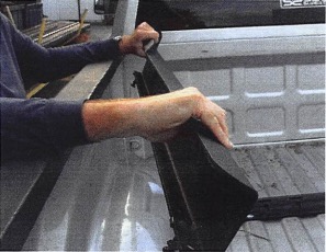
Figure 6: The bed rail being test fit onto the vehicle.
Step 9: To ensure no damage to the vehicle leave approximately a 1/4" gap between the rail and front of the bed. Figure 7 shows how big the gap should be between the rail and bed.
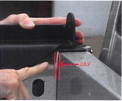
Figure 7: The 1/4" gap between the rail and bed
Step 10: To secure the bed rails you must first find where you would like clamp blocks located. This step is crucial so there are no problems with the install. On each side of the vehicle identify the most frontward and rearward spots where the clamp blocks fit inside the bed rails with no interferences. Then mark with a piece of tape the holes that line up with the clamp block. Figures 8 and 9 show the area where we found the clamp block to fit the best inside the bed rails.
NOTE: Every vehicle's bed is different. The clamp blocks may not use the same holes as pictured.
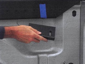
Figure 8: Test fitting the clamp block into the front portion of the bed rails.
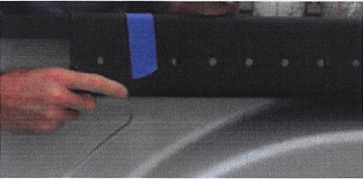
Figure 9: Test fitting the clamp block into the rear portion of the bed rails.
Step 11: To finish preparing the bed rails remove them from the vehicle. A clip nut has to be installed on the bottom holes of the bed rail. The clip nut will go where the tape was placed. Make sure there is a hole on each side of the clip nut. To install the clip nut, simply slide it onto the bed rail. Make sure the threaded end of the clip nut is on the inside of the rail. Figure 10 shows the clip nut installed onto the bed rail.
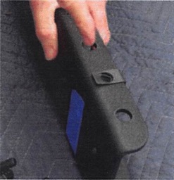
Figure 10: The clip nut installed onto the bed rail.
Step 12: Make sure to have all 4 clip nuts installed before continuing on. They should be placed on the front and back of both bed rails.
Step 13: Install (4) M10x50 bolts and M10 hex nuts into the clip nuts. The threads of the bolts should not pass the end of hte clip nut threads. Figure 11 shows the bolts installed into the clip nuts as well as proper orientation of the clamp block and nut plate.
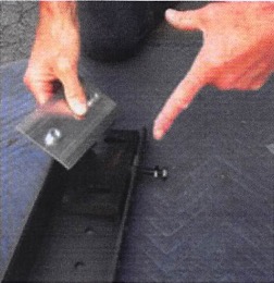
Figure 11: The bolts installed into the bottom of the bed rail
Step 14: To secure the bed rails reinstall on the vehicle into the same positions as when you test fit. Now slide the clamp block and nut plate onto the bed rail from behind. Make sure the lip of the clamp block is facing towards the bed rail and is at the bottom of the rail. Figure 12 shows how the clamp block and nut plate will look on the bed rail.
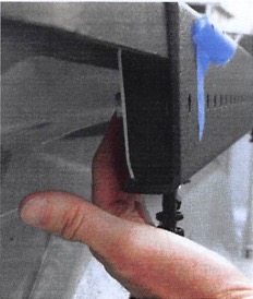
Figure 12: The clamp block and nut plate ready to be secured
Step 15: To install the nut plate use (2) M10x50 bolts. Put them through the bed rail; through the clamp block, and hand thread them into the nut plates. Then tighten the M10x50 bolt that was installed into the clip nuts, tighten until the clamp block is firmly pressed against the underside of the trucks bed lip (do not over tighten). Then using the M10 hex nut, thread it up against the clip nut so the M10x50 bolt does not unthread itself. Now torque the bolts in the nut plate to 45 ft-lbs. Figure 13 shows the bolts getting tightened down.
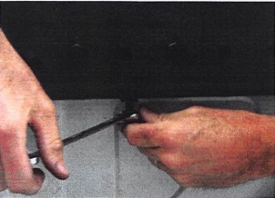
Figure 13: The bolts getting tightened down to secure the bed rails.
Step 16: Repeat step 15 for the other 3 clamp blocks and nut plates.
Step 17: To finish securing the bed rails install one turnbuckle on each side.
NOTE:
- For 6 1/2 ft bed use the turnbuckle with the long J hook on one end and a 3 1/2" hook bolt.
- For 5 1/2" ft bed use the turnbuckle with 2 3 1/2" hook bolts.
- For 8ft bed modification required (hooks on each end of the bed have to be installed)
Step 18: To install the turnbuckle, put the hook through a bottom hole of the bed rail. Figure 14 shows the hook of the turnbuckle in the wrong spot, you would not be able to fully tighten it. Figure 15 shows the turnbuckle repositioned on the bed rails and can be fully tightened.
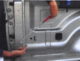
Figure 14: The turnbuckle installed improperly, no way of fully tightening it
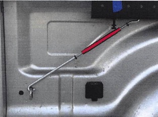
Figure 15: The turnbuckle in a much better position ready to be fully tightened
Step 19: To tighten the turnbuckle, first make it hand tight and then tighten it down another half a turn using a crescent wrench. Once the turnbuckle is tight use a 14mm wrench to tighten the (2) jam nuts. There is one on each end of the turnbuckle. Hold the turnbuckle with one wrench while the jam nuts are being tightened. Figure 16 show the jam nuts being tightened against the turnbuckle.
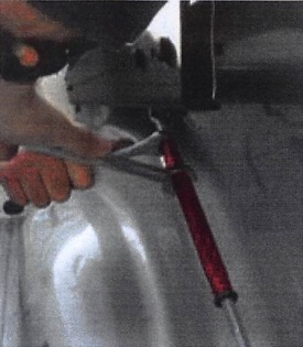
Figure 16: The jam nuts securing the turnbuckle
Step 20: Repeat for the other side of the vehicle. Figure 17 shows the turnbuckles properly installed.
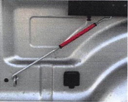
Figure 17: The turnbuckle properly installed onto the vehicle
Step 21: To install the riser assemblies onto the bed rail you will use the 1/2 - 13x12 bolt with the 1/2" washer. Place one riser into the slot on the bed rail, the long portion of the riser should be closer to the cab. Now slide the 1/2 - 13x12 bolt with washer into the bed rail and through the riser, insert bolt from the rear of the vehicle. Figure 18 shows the bolt with washer being installed through the riser.
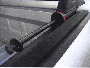
Figure 18: The 1/2 - 13x12 bolt and 1/2" washer going through the riser
Step 22: To make sure the vehicle or riser assembly does not get damaged, lay some foam between the riser and bed rail. Figure 19 shows the foam being used to support and protect the riser.
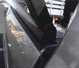
Figure 19: The foam placed in-between the riser and rail for protection.
Step 23: Repeat steps 21 and 22 for the other side of the vehicle.
Step 24: To secure the riser a headache end fitting must be installed first. Slide the headache end onto the 1/2 - 13x12 bolt with the end fitting angled toward the cab of the truck. Then place a 1/2" washer and 1/2" lock nut on the bolt. Make sure to not tighten the lock nut at this time. Figure 20 shows the proper way the headache end fitting has to be installed.
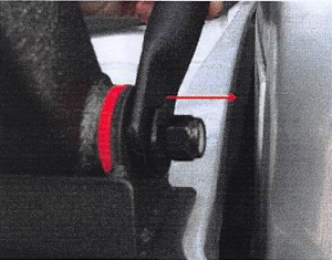
Figure 20: The red arrow shows what direction the headache fitting should be facing.
Step 25: Repeat step 24 for the other side of the vehicle.
Step 26: To assemble the headache outer tube start by sliding the headache end fitting into the headache outer tube (do this with the headache fitting that is not installed onto the vehicle). Then secure the outer tube and the fitting together using (1) M10x50 bolt, (2) M10 washers, and (1) M10 lock nut leave hand tight. Repeat for the other side of the vehicle. Figure 21 shows the headache tubes properly assembled.
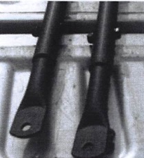
Figure 21: The headache tubes properly assembled
Step 27: To attach the headache tube assembly onto the headache end fittings installed in step 24. Use (1) M10x50 bolt, (2) M10 washers, and (1) M10 lock nut. Make sure the headache end fittings are already attached to the headache outer tube and are faving away from the cab. The M10 lock nuts should just be hand tight at this point. Repeat for hte other side of the vehicle. Figure 22 shows how the heache assemblies should look and how to rest them on the vehicle temporarily until later in the install.
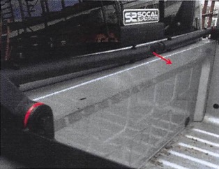
Figure 22: The headache assemblies attached to the vehicle, the arrows show the direction the (2) headache end fittings should face
Step 28: To assemble the side rail assembly you will need (4) M10x30 hex bolts, and (4) M10 washers. Lay the side rail assembly onto the ground and hold the racking tube bracket up to the pre-threaded holes. The large rectangular slots of the racking tube bracket should be facing up. Now secure the racking tube bracket by hand threading the M10x30 bolts and M10 washers into the side rail assemblies. Then torque the bolts to 25-30 ft-lbs. Repeat for other side. Figure 23 shows how to attach the side rail to the racking tube.
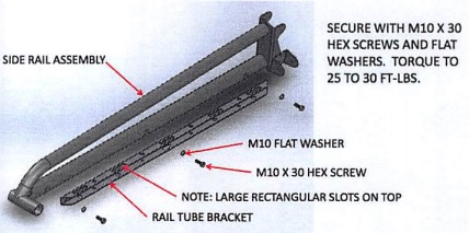
Figure 23: The assembly of the racking tube bracket being attached to the side rail assembly
*****NOTE*****
IT IS HIGHLY RECOMMENDED TO PLACE A BLANKET OR OTHER HEAVY, BUT SOFT, PROTECTIVE COVER OTHER THE TOP OF THE CAB TO PREVENT SCRATCHES.
Step 29: Start by installing one of the rack assemblies, we highly recommend a second person's assistance. Lift the rack assembly onto the riser assembly; line up the holes, and then using (1) M10x90 hex bolt, (1) M10 washer, and (1) M10 lock nut, secure the two assemblies together. Do not tighten the nut; just rest the assembly on the protective cover on the roof. Repeat for the other side. Figure 24 shows the rack assembly being lined up to the riser assembly.
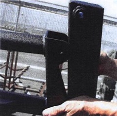
Figure 24: Rack assembly ready to be mounted to the riser assembly
Step 30: To install the forward cross tube to the side rail assemblies use (4) M10x1.5x70 carriage bolts, (4) M10 washers, and (4) lock nuts. Attach the forward cross tube to one of the side rail assemblies, then attach the other side rail assembly. Make sure the lop on the cross tube is facing inward. Figure 25 shows the cross tube securing the side rail assemblies.
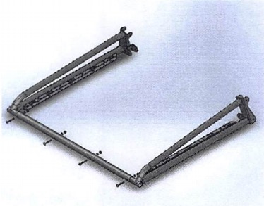
Figure 25: The cross tube securing the side rail assemblies
Step 31: To install the 5 rectangular racking tubes, slide one into the slots on the racking bracket on each side. Then secure each end of the tube using (1) M10x45 carriage bolt, (1) M10 washer, and (1) lock nut. Do not tighten at this time. Now repeat for the other (4) racking tubes. Figure 26 shows the racking tubes being installed onto the racking bracket.
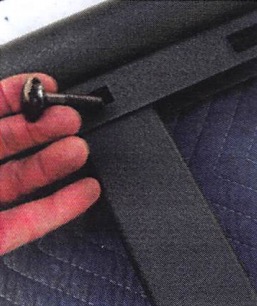
Figure 26: Carriage bolt being installed into racking tube
Step 32: To install the rear cross tube, line one end up to the bracket on the riser assembly. Secure the cross tube with (1) M10x90 hex bolts, (1) M10 washer, and (1) M10 lock nut. Do not tighten at this time. Figure 27 shows the cross tube mounted to the riser assembly.
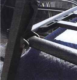
Figure 27: The cross tube mounted to the riser assembly
*****NOTE*****
IF AN OPTIONAL TIRE CARRIER IS BEING INSTALLED, IT WILL BE INSTALLED ALONG WITH THE HEADACHE TUBES USING THE M12 X 100 MM HEX BOLTS THAT COME WITH THE KIT INSTEAD OF THE M10 X 90 BOLT.
Step 33: Now raise the headache tubes, they are mounted on the cab side of the cross tube. Using (1) M10x90 hex bolt, (1) M10 washer, and (1) M10 lock nut, secure the headache tube to the cross tube. Repeat for the other headache tube. Do not tighten at this time. Figure 28 shows the headache tube mounted to the cross tube.
NOTE: For the optional tire carrier, it will mount to the same location on the cross tube but on the bed side. Use (1) M10x100 bolt, (1) M10 washer, and (1) M10 locknut to secure the tire carrier. Do not tighten the bolts at this time. Figure 29 shows the tire carrier mounted to the cross tube.
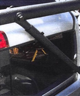
Figure 28: The headache tube secured to the cross tube
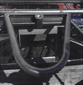
Figure 29: The tire carrier installed onto the cross tube
Step 34: Make sure the rck is straight and everything looks like it is properly placed. Then tighten all the bolts in the order listed below.
Torque Chart:
- Riser bolt/nut 80 ft-lbs
- Headache tubes 45 ft-lbs
- Crosstube rear 45 ft-lbs
- Racking tube bracket 35 ft-lbs
- Cross tube front 40 ft-lbs
- Racking tubes 40 ft-lbs
Step 35: Your ADV Rack is now ready for adventure!
Wilco Offroad Limited Lifetime Warranty
Wilco Offroad offers a limited lifetime warranty on the structure of each product to the original purchaser.
Exclusions:
1. Products that have been abused, crashed, altered, modified, or installed on vehicles other than those approved by Wilco Offroad.
2. Cost of the original installation, removal, or reinstallation.
3. Damages and shipping charges.
4. Latch bushings, safety cable assembly, bolts, nuts, latch pins, tether cables, and thrust washers. (These parts are subject to wear and are not considered defective when worn)
1 Year Powder Coat Warranty
1-year powder coat warranty against manufacture defects. Covers corrosion issues, bubbling, and cracking to the powder coated finish.
Exclusions:
1. Scrapes, scratches, dents, dings, chips, and negligence
2. Damage due to shipping.
3. Accidents, impact by rocks, trees, obstacles, or other aspects of the use environment.
Contact Us
For questions about warranty, call 1-877-945-2684 or email [email protected]
