 FREE 1 to 3-Day Delivery on Orders $149+ Details
How to Install Westin Molded/Sure Grip Running Board Mounting Kit - Black on your F-150
CAUTION!! BEFORE BEGINNING THIS INSTALLATION PROCEDURE, READ THROUGH INSTRUCTIONS CAREFULLY AND COMPLETELY.
HARDWARE KIT
*One bracket for front passenger side, one bracket (with notch) for front driver side.
Each Universal Running Board fitment has a specific Bracket Kit which coincides with specific vehicles. Make sure the kit you received coincides with your vehicle. Read all instructions thoroughly before you begin installing the running boards and brackets. Pre-fit all pieces and check the hardware list to be sure all the parts are included before beginning.
FORD F-150 EXTENDED CAB:
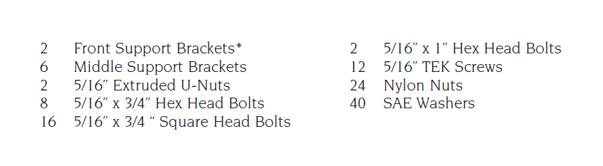
STEP 1: NOTE: Steps 1-5 apply to the Ford F150/F250 Extended Cab. See Step 6-11 for the “Supercrew”. Locate the (8) pinch weld factory holes under the vehicle. Starting from the front wheel going toward the back wheel, using the holes in locations 1, 3, 5 and 8, mount the brackets to the pinch using 5/16 bolts, washers and nylock nuts. DO NOT TIGHTEN. NOTE: Before you mount the bracket location (1) you will find in your kit a U nut and a 5/16 x 1" hex bolt. That nut goes in the upper back side of the factory hole of the vehicle so that you may use a hex head bolt and washer on the front bracket to fasten down. See Figures 1 & 2.
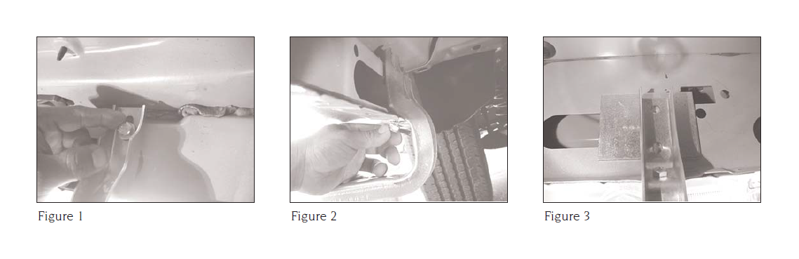
STEP 2: Now that you have your brackets in place, slide a plate between the brackets and the body of the vehicle. Line up the holes of the plate. See Figure 3. NOTE: THIS PLATE IS NECESSARY FOR SUPPORT. IT MUST BE INSTALLED.
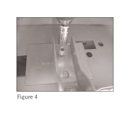
STEP 3: After installing the plate, run two TEK screws in each bracket in the
appropriate location and fasten down the hex bolt as shown in Figure 4.
STEP 4: Mount Step Boards to Brackets. Slide (8) eight of the Square Head Bolts into the two outside slots in the aluminum support plate.
Note: Slide (4) four in the inner most slot and (4) four in the outer most slot. Note: Debur the aluminum channel if the square bolts cannot pass through the opening. Use (8) nylock nuts and washers to attach the board to the proper location, by adjusting the board from side to side, centering the board to the truck, then tighten the nylock nuts.
STEP 5: Repeat the installation steps for the other side to complete the board installation. For the lighted version, proceed to Step 12.
FORD F-150 SUPERCREW
STEP 6: Locate the pinch weld under the vehicle. Starting from the pinch weld at the rear of the cab to the front of the cab, measure:
• 12-1/2” to factory hole
• 30” to drill hole
• 52-1/4” to drill hole
• use the rear set of mounting holes
on front factory mounting position.
NOTE: Before you mount the bracket at location (1) you will find in your kit a U nut and a 5/16 x 1" hex bolt. That nut goes in the upper back side of the factory hole of the vehicle so that you may use a hex head bolt and washer on the front bracket to fasten down. FOR FRONT BRACKETS: Place extruded u-nut into the second hole of the front factory mounting location. (PASSENGER SIDE)
STEP 7: Place Bracket in place and fasten with 5/16” x 1” hex head bolt through top hole of bracket and 5/16” x ¾” hex head bolt through pinch weld and bracket with Nylock nut and washer. (DRIVER’S SIDE)
STEP 8: FOR CENTER BRACKETS: Mark and drill 5/16” hole in pinch weld at suggested locations.
STEP 9: Place bracket in position and insert 5/16” x 3/4” hex head bolt with washer through pinch weld and bracket and fasten with washer and Nylock nut.
STEP 10: Tighten pinch weld bolts and run self-tapping TEK screws into tip holes of brackets.
STEP 11: Mount Step Boards to Brackets. Slide (12) twelve of the Square Head Bolts into the two outside slots in the aluminum support plate. Note: Slide (6) six in the inner most slot and (6) six in the outer most slot. Note: Debur the aluminum channel if the square bolts cannot pass through the opening. Use (12) twelve nylock nuts and washers to attach the board to the proper location, by adjusting the board from side to side centering the board to the truck then tighten the nylock nuts. Tighten all the remaining hardware and test the Step Boards for attachment. This concludes the installation procedure for the Step Boards without lights. For the Lighted version, proceed to STEP 12.
INSTALLING THE LIGHTS & WIRING HARNESS TO YOUR STEP BOARDS (FOR LIGHTED VERSION):
STEP 12: A three piece wiring harness is included with the Lighted Step Board. The harness includes four (4) light sockets and three plugs. Carefully plan a wire route from the right side Step Board to the left. Then choose a pass-through point (floor board to inner cab) for the wire harness. WESTIN RECOMMENDS YOU USE A PROFESSIONAL TO INSTALL THE WIRING HARNESS—SEE STEPS 14-19 BELOW.
STEP 13: Attach wire harness and lights. Be sure all rubber seals are in place before installation. The rubber grommet around the red and blue wires going into rear of sockets should be completely inserted and recessed about 1/4”. NOTE: Ensure the longevity of your lights by removing the bulb and placing a small amount of white grease into the sockets and replacing the bulb. Place a small amount of RTV Silicone where the lights go into the socket. This keeps the sockets dry and adds to longevity. Screw lights into sockets and run conduit in center slot of aluminum base board. This will hold the harness in place.
STEP 14: GENERAL TIPS FOR WIRING HARNESS INSTALLATION. PLEASE NOTE: The light wiring harness installation requires splicing into your vehicle’s electrical system. WESTIN HIGHLY RECOMMENDS THAT YOU USE A PROFESSIONAL TO INSTALL THE WIRING HARNESS FOR THE LIGHTED VERSION.
STEP 15: After choosing a pass through point follow this sequence: CAUTION: ALWAYS US A FUSED ( ) POSITIVE SUPPLY SOURCE AND UNDERCOAT SEAL FOR HARSH WEATHER. Route long lead harness to short lead harness and plug connector securely. Note: Avoid areas of excess heat, vibration, pinch or rotation when securing harness to vehicle. For this vehicle you can find a power source on the passenger side rocker panel. Pull up rocker strip to get to harness and using a test light try the black wire with the blue stripe.
STEP 16: Plug open-ended connection into unused connection. Note: Either connector on short lead board harness will work. Route open ended wire harness through truck cab. Note: Find the closest position to door light switch lead wire. Pass seal through hole. Use silicone or permanent sealer.
STEP 17: Connect positive and negative lead wires to vehicle sources (dome light or courtesy light under dash). Use vehicle door switch for ground lead source and appropriate positive lead for supply. ALWAYS USE A FUSED POSITIVE ( ) POWER SOURCE.
STEP 18: Test circuit for proper function and connection before tape sealing all exposed wire.
STEP 19: Under-coat the Step Boards, Brackets and all electrical wires, connections and lenses for harsh weather conditions. INSTALLATION IS COMPLETE.
THANK YOU FOR CHOOSING WESTIN!

