 FREE 1 to 3-Day Delivery on Orders $149+ Details
How to Install Westin Pro Traxx 4 in. Oval Side Step Bars - Stainless Steel on your F-150

Shop Parts in this Guide
PROCEDURE
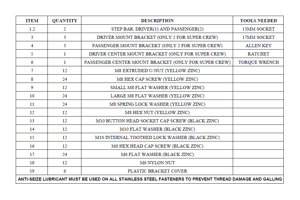
1. Remove contents from box, verify if all parts listed are present and free from damage.
Carefully read and understand all instructions before attempting installation.
Failure to identify damage before installation could lead to a rejection of any claim.
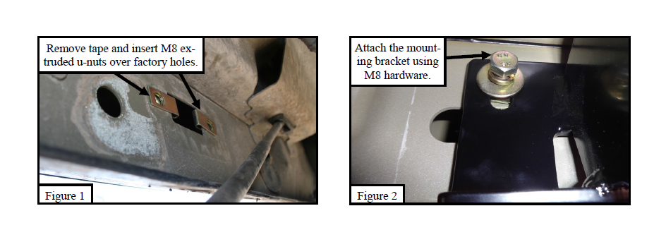
2. Starting on the drivers side rocker panel, locate a piece of black tape. Remove the tape to reveal a rectangle hole. Take (2) M8 extruded u-nuts (Item 7) and place them over the two round holes located vertically into the rocker panel. See Figure 1.
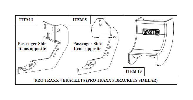
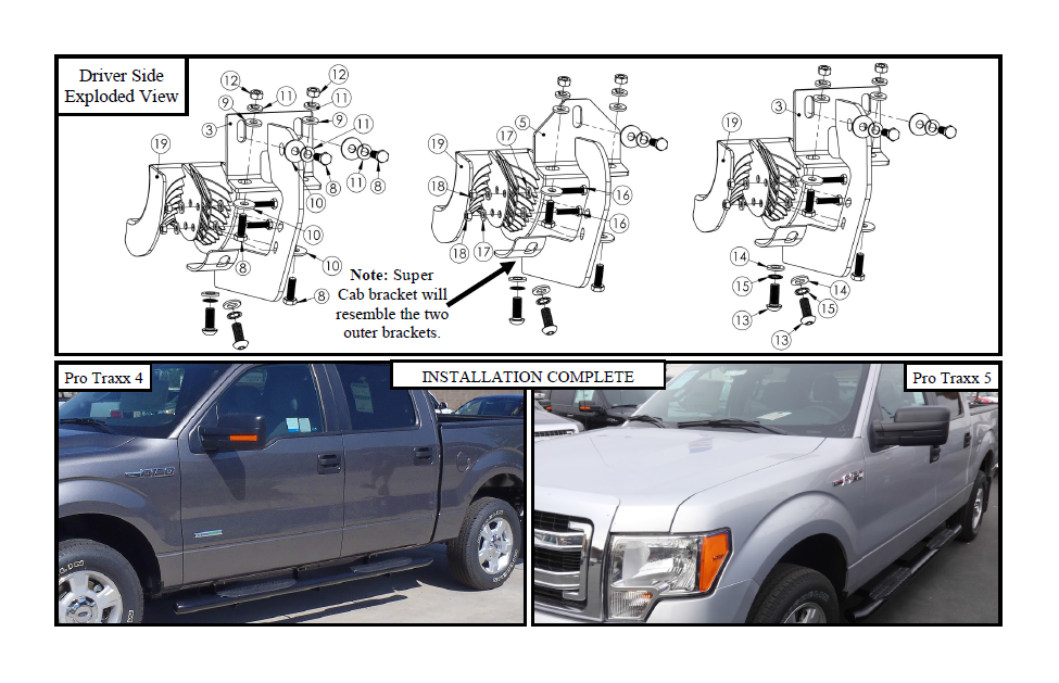
3. Take the drivers side front mounting bracket (Item 3), and attach it to the previously installed M8 extruded u-nut using (2) M8 hex cap screws (Item 8), (2) M8 lock washers (Item 11), and (2) large M8 flat washers (Item 10). Do not fully tighten at this time, the cradles will face the rear of the vehicle. See Figure 2.
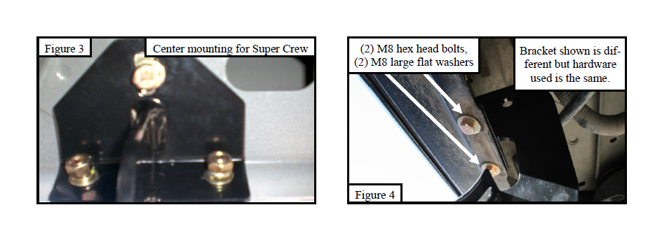
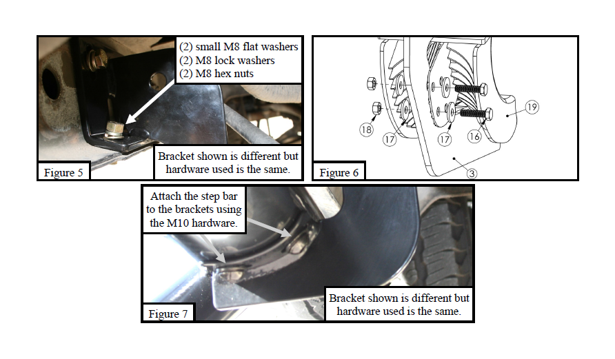
4. Attach the mounting bracket to the bottom holes in the rocker panel using (2) M8 hex cap screws (Item 8), (2) large M8 flat washers (Item 10), (2) small M8 flat washers (Item 9), (2) M8 lock washers (Item 11), and (4) M8 hex nuts (Item 12). Do not fully tighten at this time. See Figures 4 and 5.
5. Repeat Steps 2-4 for the center and r ear mounting br ackets. For Super Cr ew P/N: 21-23520, 21-23525, 21-53520 & 21- 53525, the center brackets will mount only using (1) M8 extruded u-nuts (Item 7). See Figure 3.
6. Locate Plastic Bracket Cover (Item 19) and install onto brackets using the provided M6 hardware (Items 16-18). (Figure 6)
7. Take the drivers side step bar and place it onto the mounting bracket cradles; align the step bars with the mounting holes in the brackets and attach using (6) M10 button head socket cap screws (Item 13), (6) M10 internal toothed lock washers (Item 15), and (6) M10 flat washers (Item 14). See Figure 7. Do not fully tighten at this time.
8. Align and adjust the step bar as needed then fully tighten all hardware at this time. Torque all M8 hardware to 15-18 ft-lbs, M10 stainless hardware to 30-35 ft-lbs, and M6 hardware to 5-7 ft-lbs.
9. Repeat Steps 2-8 for the passenger side.
Care Instructions
REGULAR WAXING IS RECOMMENDED. DO NOT USE ANY TYPE OF POLISH OR WAX THAT MAY CONTAIN ABRASIVES.
STAINLESS STEEL PRODUCTS CAN BE CLEANED WITH MILD SOAP AND WATER. STAINLESS STEEL POLISH SHOULD BE USED TO POLISH SMALL SCRATCHES.
GLOSS BLACK FINISHES SHOULD BE CLEANED WITH MILD SOAP AND WATER.
WARNING
FASTENERS:
All Westin supplied fasteners must be utilized and installed in accordance with the installation instructions and apply torque to the specifications as defined. DOUBLE CHECK ALL FASTENERS BEFORE INITIAL USE, AND PERIODICALLY IN THE FUTURE TO ENSURE PROPER FUNCTION AND SAFETY.
DRILLING:
Most Westin products do not require drilling for installation. If drilling is defined as required, use caution when drilling a vehicle. FAILURE TO REVIEW AN AREA TO BE DRILLED MAY RESULT IN PERSONAL INJURY AND/OR INJURY TO OTHERS AS WELL AS VEHICLE DAMAGE.
EYE PROTECTION:
ALWAYS WEAR SAFETY GLASSES OR GOGGLES DURING THE INSTALLATION PROCESS TO AVOID PERSONAL INJURY.
MAXIMUM TOWING/CARRYING CAPACITY:
The Westin Receiver Hitches will have a visible tow rating label affixed directly on the product. User should never exceed the vehicle manufacturers maximum tow and weight rating regardless of the capacity of the hitch. FAILURE TO FOLLOW THESE GUIDELINES WILL VOID THE WESTIN WARRANTY AND MAY RESULT IN PERSONAL INJURY AND/OR INJURY TO OTHERS AS WELL AS VEHICLE DAMAGE.
