FREE 1 to 3-Day Delivery on Orders $149+ Details
How to Install Westin ProTraxx 5 in. Oval WTW Side Step Bar - Stainless Steel on your F-150
Tools Required
- 13MM SOCKET
- TORQUE WRENCH
- RATCHET
- 6MM HEX KEY
- SOCKET EXT.
- 16MM SOCKET
- 18MM SOCKET
- 18MM WRENCH

Shop Parts in this Guide
1. Remove contents from box, verify if all parts listed are present and free from damage.
Carefully read and understand all instructions before attempting installation.
Failure to identify damage before installation could lead to a rejection of any claim.
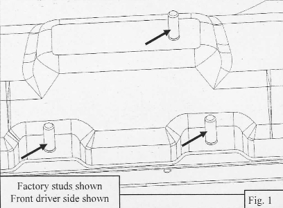
2. Start installation on the driver's side. On the rocker panel find locations of factory studs. In each location there should be 3 studs. (Note: Super Cab has two locations and Super Crew has three locations.) See Fig. I.
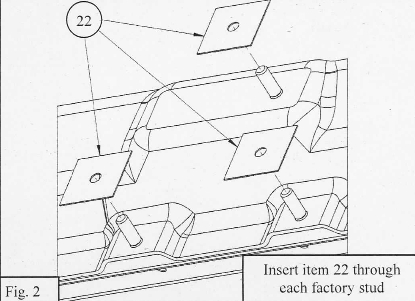
3. Insert (I) M8 Plastic Retainer Square (Item 22) on each factory stud. (Note: There will be 6 extra plastic retainer squares for the Super Cab model.) See Fig. 2.
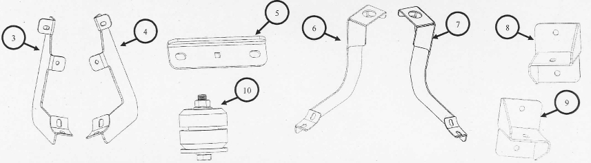
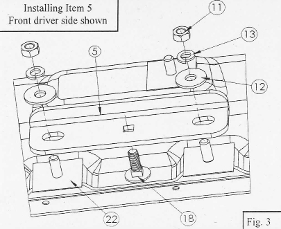
4. I11se1i the M8 round head square neck bolt (Item 18) through the Universal Mounting Bracket's square hole. Then inset the Universal Mounting Bracket (Item 5) onto the two lower factory studs. Loosely secure it with (2) M8 hex nut, (2) M8 split lock washer, and (2) M8 flat washer. Repeat for any other location with factory studs. (Note: For Super Cab model there will be 4 Universal Mounting Brackets (Item 5) and for the Super Crew model there are 6.) See Fig. 3.
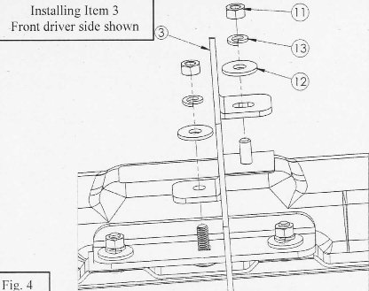
5. Return to the front location of factory studs. Locate (1) Front Mounting Bracket "A" (Item 3) and align the circular hole with the M8 round head square neck bolt (Item 18) and the slot with the top factory stud. Loosely secure it with (2) M8 hex nut, (2) M8 split lock washer, and (2) M8 flat washer. See Fig. 4.
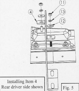
6. For the rear and center location with the factory studs use Rear Mounting Bracket "B" (Item 4). Use same hardware as in step 5 to loosely secure brackets. Super Cab model will have extra hardware. (Note: The Super Crew model will have 2 extra Rear Mounting Brackets "B", due to an extra center location of factory studs.) See Fig. 5.
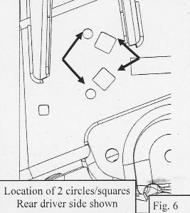
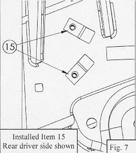
7. Locate two circular and two square holes on the frame, located near the rear of vehicle. See Fig. 6.
8. Using (2) M 10 U-Nut Clip (Jtem 15), insert them into the square holes on frame. Make sure that the circular holes of the frame are concentric with the circular holes of the MIO U-Nut Clips. See Fig. 7.
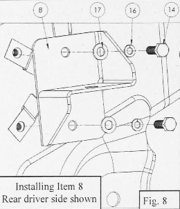
9. Locate Driver Top Isolator Bracket (Item 8). Align holes of the Driver Top Isolator Bracket with the holes of the fu-nut clips. Using (2) MIO hex bolt, (2) MIO split lock washer, and (2) MIO flat washlr loosely secure the Driver Top Isolator Bracket to the frame. See Fig. 8.
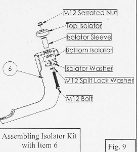
10. Locate the Isolator Kit (Item I 0). Isolator Kit should have (I) isolator sleeve, ( 1) top isolator, (I) bottom isolator, (I) isolator washer, (1) Ml 2 split lock washer, (1) M 12 serrated nut, and(!) Ml2 bolt. Assemble the Iso:ator kit with the Driver Bottom Isolator Bracket (Item 6). See Fig. 9.
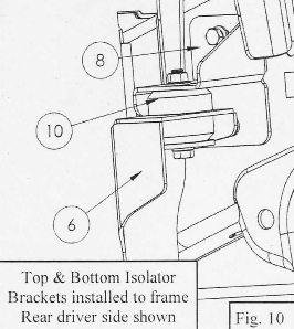
11. Install assembly (Item 6 & Item I 0) onto the Driver Top Isolator Bracket (Item 8). Loosely install using the (I) M 12 serrated nut that comes with the Isolator Kit. See Fig. 10.
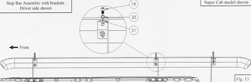
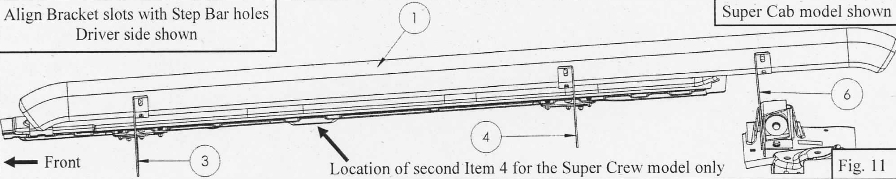
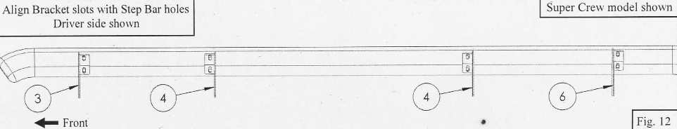
12. Locate the Driver Step Bar Assembly (Item I) and align it with the brackets. (Note: Super Cab model will have 3 brackets and Super Crew will have 4 brackets.) See Fig. 11 & 12.
13. Loosely install the Driver Step Bar Assembly using M 10 button head cap screw (Item 19), Ml O internal toothed lock washer (Item 20), and Ml O flat washer (Item 21 ). (Note: Super Cab model with have extra hardware.) See Fig. 13.
14. Align and adjust the step bar and brackets as necessary then tighten and torque all fasteners as follows: M8 to 20 ft-lbs, M 10 30 ft-lbs.
15. Repeat for the passenger side.