FREE 1 to 3-Day Delivery on Orders $149+ Details
How to Install Westin HDX Running Boards - Textured Black on your F-150
Installation Time
2 hours
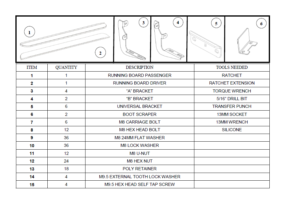
Tools Required
- RATCHET
- RATCHET EXTENSION
- TORQUE WRENCH
- 5/16” DRILL BIT
- TRANSFER PUNCH
- 13MM SOCKET
- 13MM WRENCH
- SILICONE
ANTI-SEIZE LUBRICANT MUST BE USED ON ALL STAINLESS STEEL FASTENERS TO PREVENT THREAD DAMAGE AND GALLING .
1. Remove contents from box, verify if all parts listed are present and free from damage. Carefully read and understand all instructions before attempting installation.
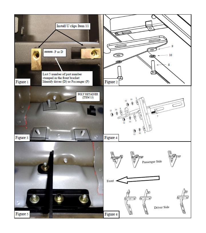
2. Identify driver and passenger side running boards and install M8 u-nut clips (Item 11) to the underside of the boards. Figure 1.
3. Locate three mount locations at each side of the rocker panel (Figure 3).
4. Place 1 poly retainer (item 13) on each threaded stud (Figure 3).
Important: Poly r etainer must be used to insulate and pr event the contact between br acket (Made of steel) and rocker panel (Made of aluminum). Contact between these two materials creates corrosion.
5. Mount 1x Universal bracket (Item 5) on Bracket A (Item 3) and Bracket B (Item 4) Using the hardware on Figure 4.
6. Install mounting brackets at the rocker panel (Figure 5) using the hardware on Figure 4. And follow (Figure 6) for placement brackets order. Do not fully tighten at this time.
7. Take the drivers side running board and place it onto the mounting bracket cradles; align the running board with the mounting holes in the brackets and attach using (6x) M8 hex head bolts (item 8), (6x) M8 lock washers (item 10), and (6x) M8 large flat washers (item 9) (Figure 2). Do not fully tighten at this time.
8. Align and adjust the running board as needed then fully tighten all hardware at this time. Torque M8 hardware to 20 ft lbs.
9. Repeat steps 4-8 for the passenger side.
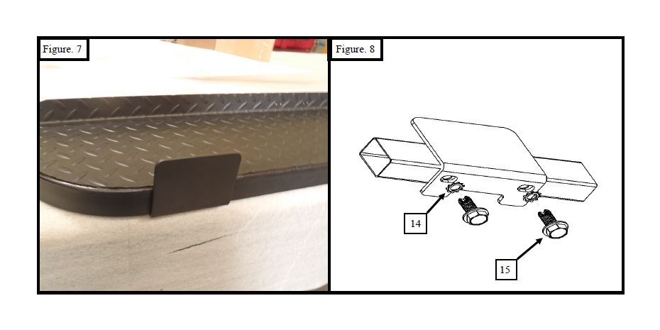
Boot scraper (OPTIONAL) can be installed anywher e on the under side fr ont edge of the r unning boar d. Place the boot scraper (item 6) on the underside of the running board rail. Then mark the position that it will be installed using a transfer punch. Remove the boot scraper; then using a 5/16” drill bit align it with the previously made marks and drill through the bottom of the rail on the running board. Thread in (2x) 9.5mm hex head self taping screws (Item 15). Remove the screws and add some silicone sea lant in the holes to prevent rust. Attach the boot scraper (item 6) using (2x) 9.5mm Hex Flange Head Self Threading Screw (item 15) and (2x) 9.5mm external toothed lock washers (item 14). (Figure 8) Torque all M9.5 hardware to 18 ft. lbs.