FREE 1 to 3-Day Delivery on Orders $149+ Details
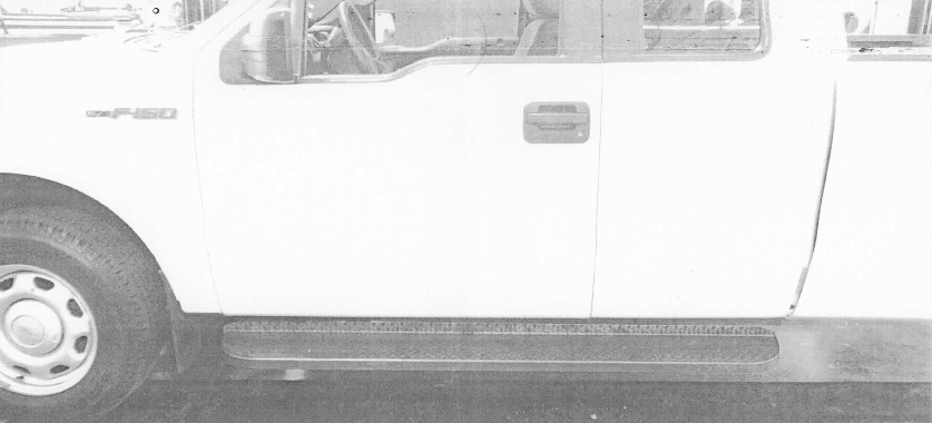
How to Install Westin HDX Running Board - Textured Black on your F-150
Tools Required
- TOOLS NEEDED
- 13MM SOCKET
- 13MM WRENCH
- RATCHET
- RATCHET EXTENSION
- TORQUE WRENCH
- 5/16" DRILL BIT
- TRANSFER PUNCH
- SILICONE
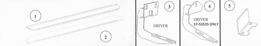
1. Remove contents from box. verify if all parts listed are present and free from damage. Carefully read and understand all instructions before attempting installation.
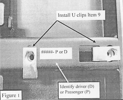
2. Identify driver and passenger side run11ing boards and install MS u-nut clips (Item 9) to the underside of the boards. Figure I.
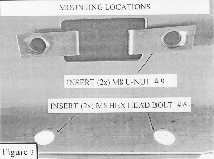
3. Starting on the drivers side rocker panel, locate a piece of black t:ipe. Remove the tape to reveal a rectangle hole. Take (2) MS nut clips (item 9) and place them over the two round holes located vertically into the rocker panel. Figure 3.
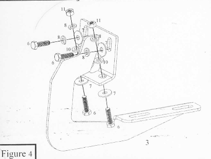
4. Take the drivers side front mounting bracket (item 3), and attach it to the previously installed nut clips using (2) MS hex head bolts (item 6). (2) MS lock washers (item 8). and (2) MS large flat washers (item 7). Do not fully tighten at this time. the cradles will face the rear of the vehicle. Figure 4.
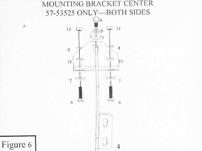
5. Attach the mounting bracket to the bottom holes in the rocker panel using l2) MS hex head bolts (item 6), (2) MS large nm washers (item 7). l2) MS llat washers (item 7), (2) MS lock washers (item 8), and (2) MS hex nuts (irem I I). Do fully tighten at this time. Figures 4 & 6.
6. Repeat steps 3-5 for the center and rear mounting brackets.
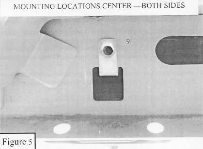
7. For 09-14 Super Crew pin 57-53525, the center brackets will mount only using (I) MS nut clip (irem 9). Figure 5.
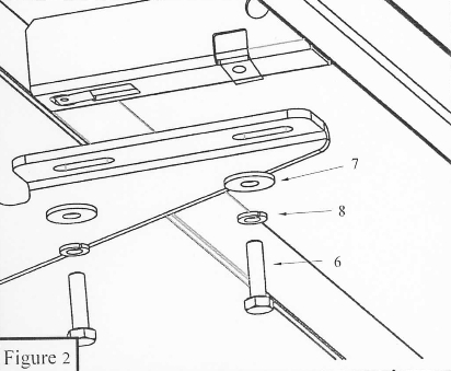
8. Take the drivers side running board and place it onto the mounting bracket cradles: align the running board with the mounting holes in the brackets and attach using (6) MS hex head bolts (item 6). (6) MS lock washers (irem 8). and (6) MS large flat washers (item 7) Figure 2. Do not fully tighten at this time.
9. Align and adjust the running board as needed then fully tighten all hardware at this time. Torque all MS hardware to 20 Ii lbs.
I 0. Repeat steps 3-8 for the passenger side.
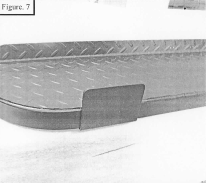
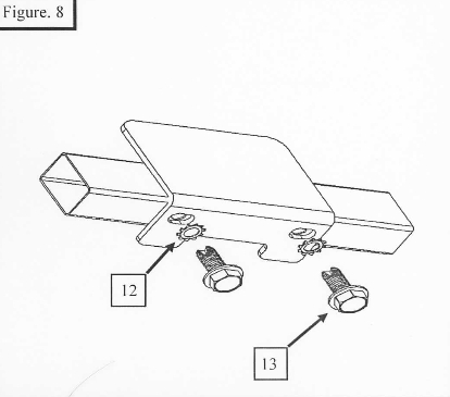
Boot scraper (OPTIONAL) can be installed anywhere on the under side fr ont edge of the running boar d. Place the boot scraper (item 5) on the underside of the running board rail. Then mark the position that it will be installed using a transfer punch. Remove the boot scraper; then using a 5/16" drill bit align it with the previously made marks and drill through the bottom of the rail 011 the running board. Thread in (2x) 9.5mm hex head selftapil)g screws. Remove the screws and add some silicone sealant in the holes to prevent rust. Attach the boot scraper (item 5) using (2x) 9.5111111 Hex Flange Head Self Threading Screw (item 13) and (2x) 9.5mm external toothed lock washers (item 12). (Figure 8 ) Torque all M9.5 hardware to 18 ft. lbs.