FREE 1 to 3-Day Delivery on Orders $149+ Details
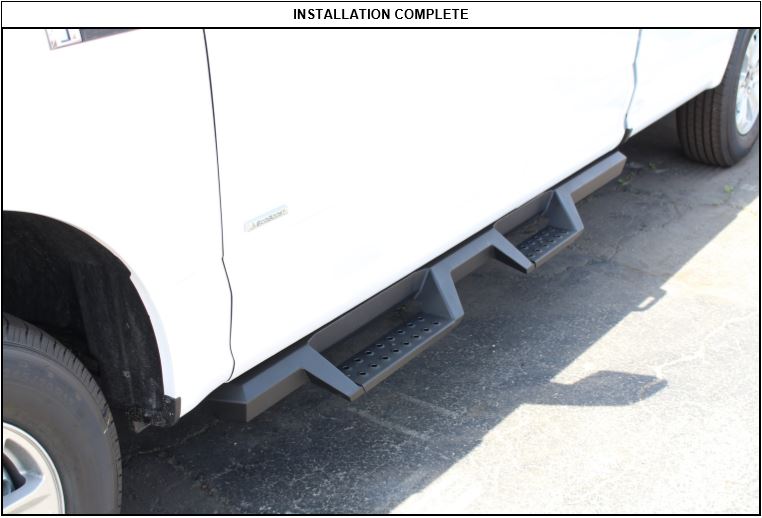
How to Install Westin HDX Drop Steps - Textured Black on your F-150
Installation Time
15 minutes
Tools Required
- Ratchet
- Torque Wrench
- 13mm Wrench
- 13mm Socket
- Socket Extension

Shop Parts in this Guide
PROCEDURE
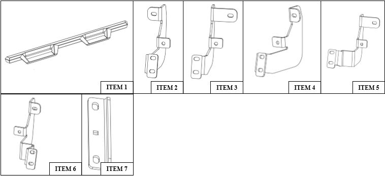
STEP 1. Remove contents from box, verify if all parts listed are present and free from damage. Carefully read and understand all instructions before attempting installation. Failure to identify damage before installation could lead to a rejection of any claim.
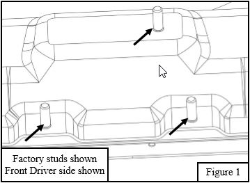
STEP 2. Start installation on driver’s side. On the rocker panel find locations of factory studs. In each location there should be 3 studs. (Note: Super Cab has two locations and Super Crew has three locations.) See Figure 1.
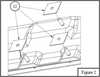
STEP 3. Insert (1) M8 Plastic Retainer (Item 12) on each factory stud. (Note: There will be 6 extra plastic retainers for the super cab model.) See Figure 2.
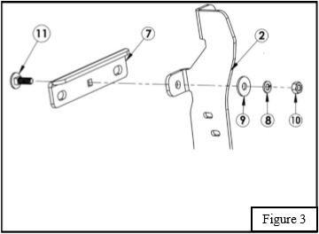
STEP 4. Insert the M8 round head square neck bolt (Item 11) through the Universal Mounting Bracket’s (Item 7) square hole. Then insert the M8 round head square neck bolt through mounting brackets (Item 2 - 6) bottom circular hole. Loosely secure with (1) M8 hex nut, (1) M8 split lock washer, and (1) M8 flat washer. (Note: For Super Cab model there will be 4 Universal Mounting Brackets and for the Super Crew model there are 6.) See Figure 3.
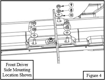
STEP 5. Align sub-assembly with the 3 factory studs. Lower 2 factory studs will align with the Universal Mounting Bracket and top factory stud will align with mounting brackets. Loosely secure sub-assembly with (3) M8 hex nut, (3) M8 split lock washer, and (3) M8 flat washer. See Figure 4. (Note: See page 3 for bracket orientation)
STEP 6. Repeat Step 3-4 for every mounting location.
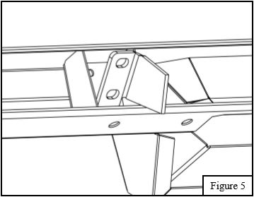
STEP 7. Tilt Board at angle to insert brackets into mounting locations. See Figure 5
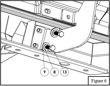
STEP 8. For Step Board installation to the previously installed mounting brackets use the supplied M8 hardware. See Figure 6.
STEP 9. Align step bar and brackets to desired positioning then torque and tighten all: M8 hardware to 20 ft-lbs.
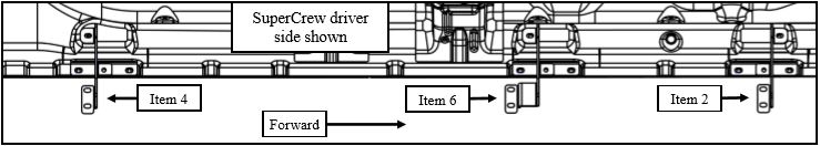
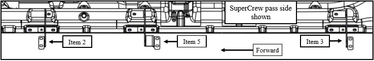
NOTE : (FOR SUPER CAB APPLICATIONS THE ORIENTATION OF BRACKETS ARE THE SAME. THE ONLY DIFFERENCE IS IT WILL NOT HAVE CENTER BRACKETS.)