FREE 1 to 3-Day Delivery on Orders $149+ Details
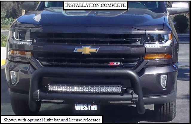
How to Install Westin Contour 3.5 in. Bull Bar - Black (14-15 Silverado 1500) on your Chevy Silverado
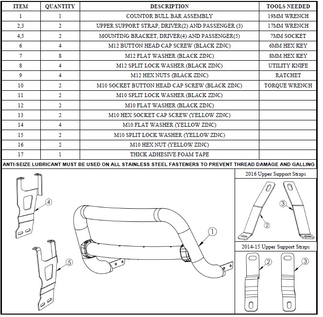
PROCEDURE
1. Remove contents from box, verify if all parts listed are present and free from damage.
Carefully read and understand all instructions before attempting installation.
Failure to identify damage before installation could lead to a rejection of any claim.
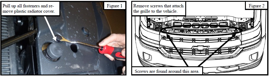
2. Remove the radiator cover to reveal screws that attach the grille to the front of vehicle. See Figure 1.
3. Remove the screws that attach the grille to the front of vehicle. Carefully pull the grille off the vehicle. See Figure 2.
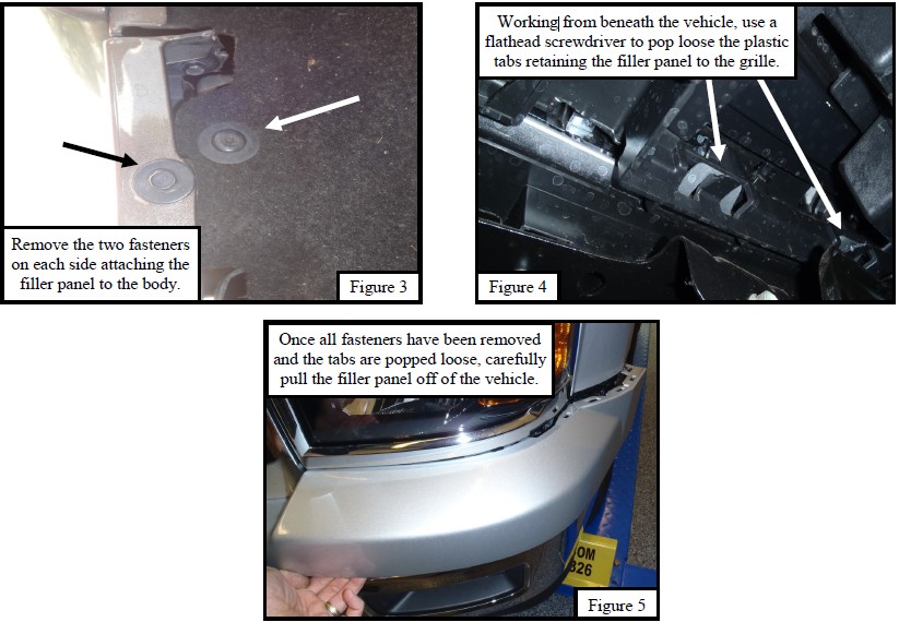
4. For 2014 - 2015 models: Remove the bumper filler panel between the front bumper and the grille. Refer to Figures 3-5.
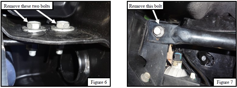
5. Start installation on the driver side, underneath the front of the vehicle. Locate and remove the bumper support bar by re-moving the two bolts on one side and one bolt on the other side of the bar. See Figures 6 & 7.
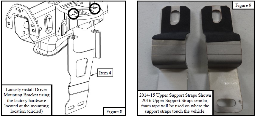
6. Locate the mounting location on the frame for the driver side mounting bracket (Item 4). The bracket fits around the front body mount near where the bumper support bar was removed. Remove the factory hardware from mounting location and loosely install the mounting bracket using the factory hardware. Refer to Figure 8. NOTE: Factory tow hooks can be re-tained but their use is impaired.
7. Repeat steps 5 - 6 for passenger side.
8. Trim the foam tape and apply it to the back of the upper support brackets as shown in Figure 9.
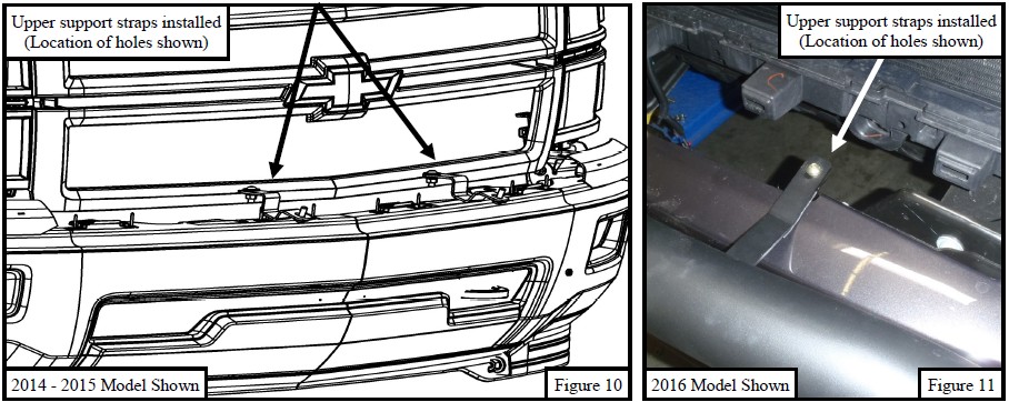
9. Loosely secure the upper support strap brackets to the existing holes in the top of the bumper. Install using (2) M10 button head cap screws, (4) M10 flat washers, (2) M10 lock washers, and (2) M10 hex nuts. See Figures 10 & 11. Do not fully tighten hardware at this time.
10. With assistance loosely install the bull bar to the mounting brackets using (4) M12 button head cap screws, (8) M12 flat washers, (4) M12 lock washers, and (4) M12 hex nuts. Refer to Figure 12.
11. Loosely attach the upper support straps to the bull bar using (2) M10 button head cap screws, (2) M10 flat washers, and (2) M10 lock washers. Refer to Figure 12.
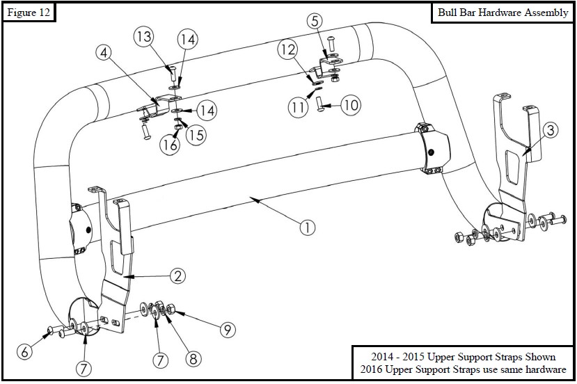
12. Align and adjust the bull bar as necessary then fully tighten all hardware at this time. Torque all M10 hardware to 30-35 ft-lbs and M12 hardware to 50-55 ft-lbs.
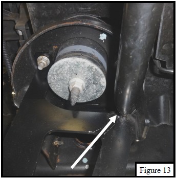
13. Re-attach the bumper support bars the opposite way they were removed. NOTE: Bumper support bars are routed through the top opening in mounting brackets. See Figure 13.
14. For 2014 - 2015 models: Re-attach the bumper filler panel in the opposite way it was removed.
15. Re-attach the grille in the opposite way it was removed.
CARE INSTRUCTIONS
REGULAR WAXING IS RECOMMENDED. DO NOT USE ANY TYPE OF POLISH OR WAX THAT MAY CONTAIN ABRASIVES.
STAINLESS STEEL PRODUCTS CAN BE CLEANED WITH MILD SOAP AND WATER. STAINLESS STEEL POLISH SHOULD BE USED TO POLISH SMALL SCRATCHES.
GLOSS BLACK FINISHES SHOULD BE CLEANED WITH MILD SOAP AND WATER.
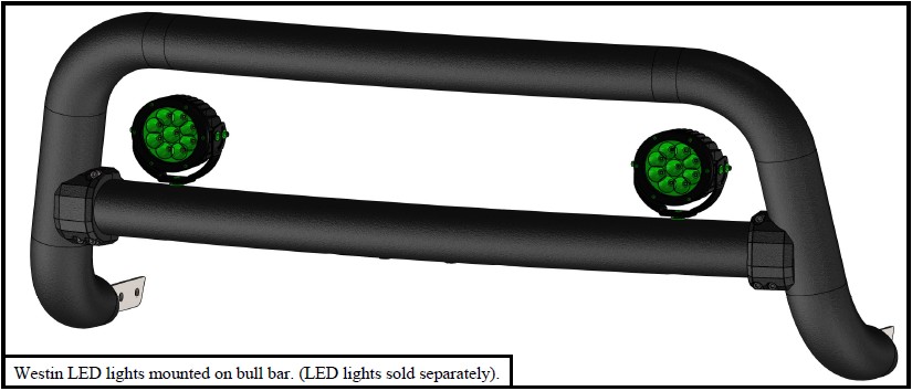
LIGHT MOUNTING INSTRUCTIONS (lights sold separately)
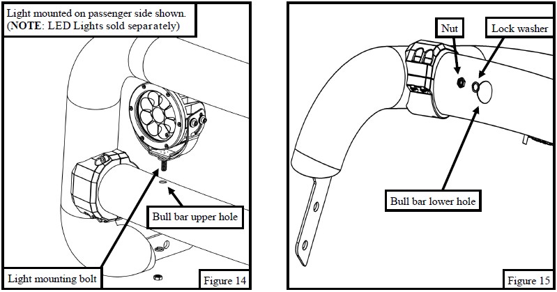
16. In order to mount the post style lights onto the bull bar start by aligning and inserting the mounting bolt of the light onto one of the upper holes in the bull bar. See Figure 14 for a picture showing this step.
17. From underneath the bull bar, insert the lock washer and nut through the hole as shown in Figure 15. NOTE: A deep well socket will need to be used in order to fasten the nut to the bolt up through the bull bar. To prevent the washer from falling off while inserting it up through the bolt, use a small piece of tape to tape it to the nut. The tape will shear off once sufficient torque is applied to the nut. Torque the hardware to the specified recom-mendations.
18. Repeat steps 1 and 2 for the installation of any additional lights.
WARNING
Failure to follow these instructions could lead to death, personal injury, and / or property damage.
FASTENERS: All Westin supplied fasteners must be utilized and installed in accordance with the installation in-structions and apply torque to the specifications as defined. DOUBLE CHECK ALL FASTENERS BEFORE INITIAL USE, AND PERIODICALLY IN THE FUTURE TO ENSURE PROPER FUNCTION AND SAFETY.
DRILLING: Most Westin products do not require drilling for installation. If drilling is defined as required, use caution when drilling a vehicle. FAILURE TO REVIEW AN AREA TO BE DRILLED MAY RESULT IN PERSONAL INJURY AND/OR INJURY TO OTHERS AS WELL AS VEHICLE DAMAGE.
EYE PROTECTION: ALWAYS WEAR SAFETY GLASSES OR GOGGLES DURING THE INSTALLATION PROCESS TO AVOID PERSONAL INJURY.
MAXIMUM TOWING/CARRYING CAPACITY: The Westin Receiver Hitches will have a visible tow rating label affixed directly on the product. Us-er should never exceed the vehicle manufacturers maximum tow and weight rating regardless of the capacity of the hitch. FAILURE TO FOLLOW THESE GUIDELINES WILL VOID THE WESTIN WARRANTY AND MAY RESULT IN PERSONAL INJURY AND/OR INJURY TO OTHERS AS WELL AS VEHICLE DAMAGE.