FREE 1 to 3-Day Delivery on Orders $149+ Details
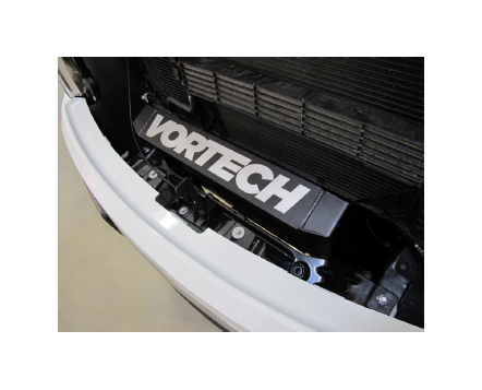
How to Install Vortech Intercooler Upgrade Black on your F-150
Installation Time
2 hours
Tools Required
- 5/16 Nut Driver
- 3/16 Allen Wrench
- Flat #2 Screwdriver
- 10mm Socket
- 13mm Socket
- Ratchet
- Ratchet Extension
- Push Pin Removal Tool

Shop Parts in this Guide
Installation Instructions
1. PREPARATION & REMOVAL
NOTE: Make note of all fastener locations for future reassembly.
A. Secure the vehicle on a lift, raise the hood & disconnect the battery. Refer to your vehicle owner's manual if you are unsure of where your vehicles lift points are located. You may do this installation without raising the vehicle, just be sure that the vehicle is on level surface with the gear selector in PARK & the parking brake engaged.
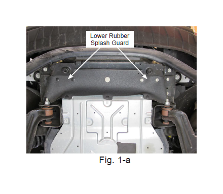
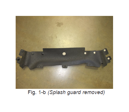
B. Remove the lower rubber splash guard by removing the (8) plastic push pins & turning the (4) white plastic fasteners counter-clockwise. See Figs. 1-a & 1-b.
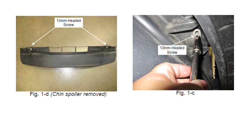
C. Using a 13mm socket, remove the (2) screws securing the chin spoiler to the vehicle. There is (1) screw per side. See Figs. 1-c & 1-d.
NOTE: Early-model vehicles do not have the bypass valve assembly attached to the cooler, therefore some steps will need to be skipped.
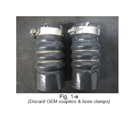
D. Loosen the (4) hose clamps on the passenger side of the cooler using the 5/16 nut driver. Remove both silicone couplers & hose clamps. These will not be reused. See Fig. 1-e
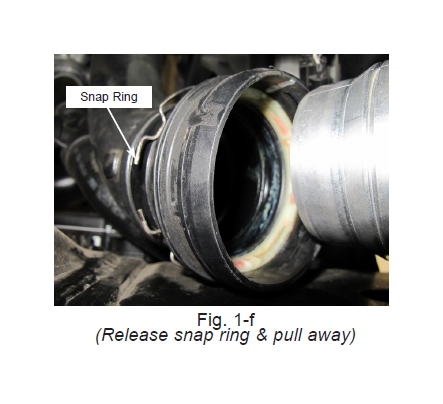
E. The driver's side discharge tube is secured by a snap ring. Using a small flathead screwdriver or pick, release the snap ring from the discharge tube, then pull the tube away from the cooler. See Fig. 1-f
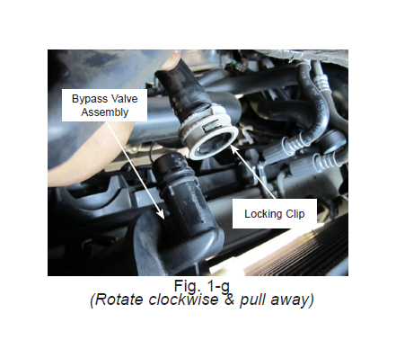
F. NOTE: Early-model F-150 skip to Step G. Locate the bypass valve tube. Turn the gray locking clip clockwise to release it from the bypass valve assembly & pull the tube away from the cooler. See Fig. 1-g
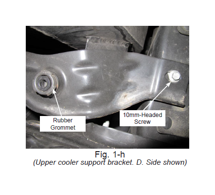
G. Remove the (2) 10mm-headed screws from the upper cooler support bracket. Remove the upper cooler support bracket, (2) screws, (2) rubber grommets & set aside as they will be reused. See Fig. 1-h.
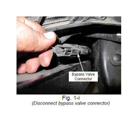
H. NOTE: Early-model F-150 skip to Step I. Unplug the bypass valve connector located on the drivers side of the cooler. See Fig. 1-iI
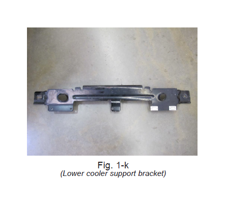
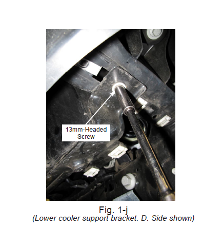
iI. Remove the (2) 13mm-headed screws from the lower cooler support bracket with the cooler attached, then lower the cooler from underneath the vehicle. Have an assistant help you with this step or use a floor jack to keep the cooler in place while you lower the cooler. Remove the (2) rubber grommets from the cooler & set aside as they will be reused. See Fig. 1-j & 1-k
Steps J & K - Early-model vehicles only
J. Early-model vehicles do not have the bypass valve assembly attached to the cooler. For this reason, we have provided a block-off plate with a fastener & o-ring. See Fig. 1-l.
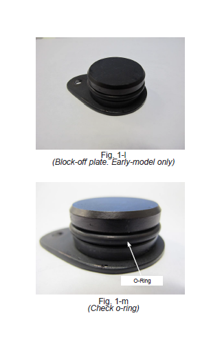
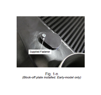
K. Prior to installation of the cooler, verify that the o-ring is in place & free of any damage. Lightly coat the o-ring with lubricant (white grease, etc.) prior to installation. Once verified, re-install the block-off plate to the cooler using the supplied fastener. See Fig. 1-m & 1-n.
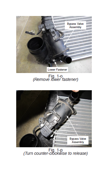
L. Remove the bypass valve assembly from the cooler by removing the fastener securing the bottom of the assembly, then turning it counter-clockwise to release it from the bore. Be sure not to damage the o-ring on the valve. See Figs. 1-o & 1-p.
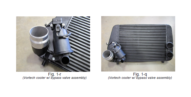
M. Remove the block-off plate from the Vortech cooler. Transfer the bypass valve assembly to the new Vortech cooler & secure the bottom of the bypass valve assembly with the provided fastener. See Figs. 1-q & 1-r.
2. CHARGE AIR COOLER INSTALLATION
A. Place (2) rubber grommets on the lower bosses of the Vortech cooler, then place the Vortech cooler onto the lower cooler support bracket. From underneath the vehicle, raise the Vortech cooler into position & loosely attach the previously removed lower cooler bracket screws to the vehicle. You may need an assistant to help raise the cooler, otherwise use a floor jack. See Fig. 2-a.
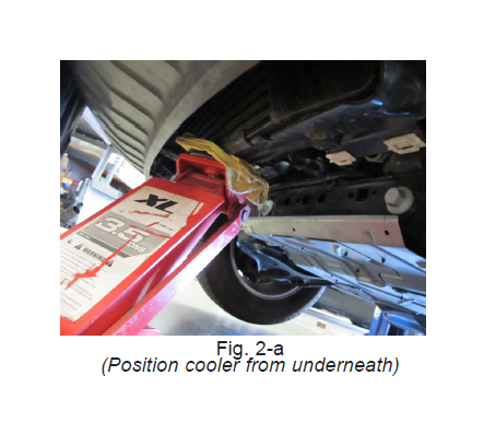
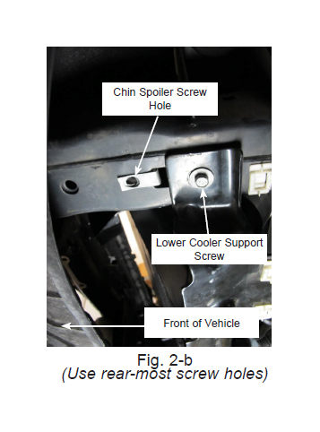
NOTE: When re-attaching the lower cooler support bracket, be sure to thread the screws into the 2 rear-most screw holes. . See Fig. 2-b.
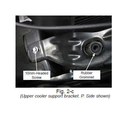
B. Place (2) rubber grommets on the upper bosses of the Vortech cooler. Position the upper cooler support bracket, then loosely attach the (2) previously removed 10mm-headed screws for the upper cooler support bracket. See Fig. 2-c.
C. Once the cooler is in position & clear of any obstructions, secure all of the screws for both cooler support brackets.
D. NOTE: Early-model F-150 skip to Step E. Reconnect bypass valve connector.
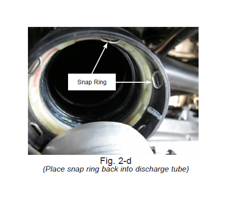
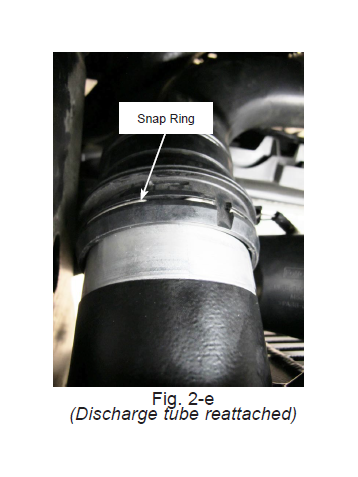
E. Locate the driver's sider discharge tube. Before attaching it to the Vortech cooler, be sure to place the snap ring back into its groove in the discharge tube. Once in place, you can slide the discharge tube onto the Vortech cooler. You will hear the snap ring click once it's locked in place. Lightly tug on the tube to verify that it is secure . See Figs. 2-d & 2-e.
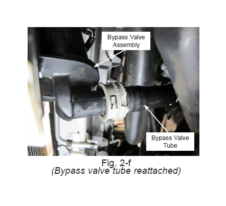
F. NOTE: Early-model F-150 skip to Step G Reattach the bypass valve tube by simply sliding it back onto the bypass valve assembly. You will hear a click once the tube is locked in place. See Fig. 2-f.
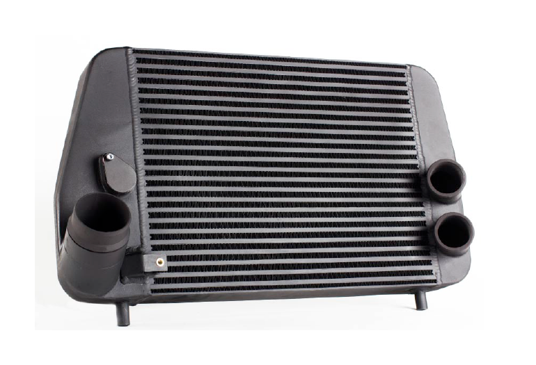
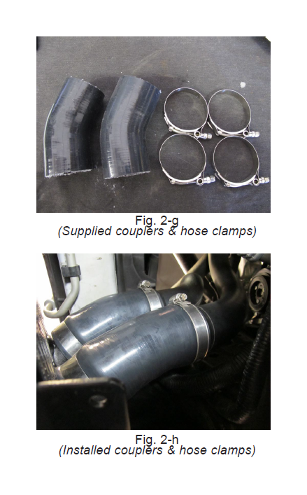
G. Due to the increased size of the Vortech cooler, alternate discharge couplers have been supplied.
H. Locate the supplied silicone couplers & hose clamps. These will be used in place of the OEM silicone couplers & clamps. See Fig. 2-g.
I. Install the silicone coupler closest to the top of the cooler first. Once in position, tighten both hose clamps. Repeat this step for the second silicone coupler. See Fig. 2-h.
3. FINAL CHECK
WARNING: Do not attempt to operate the vehicle until all components are installed and all operations of this manual are completed, including the final check.
A. Check all fasteners, silicone couplers and hose clamps for tightness and leaks.
B. Make sure there are no loose wires or anything that may get damaged.
C. Test drive the vehicle.
D. Always listen carefully for engine detonation. Discontinue heavy throttle usage if detonation is heard.