 FREE 1 to 3-Day Delivery on Orders $149+ Details
How to Install Turbosmart e-Boost Street Boost Controller - 40 PSI (97-18 All) on your Ford F-150

Shop Parts in this Guide
BEFORE YOU START – IMPORTANT NOTES
Turbosmart recommends that your E-Boost Street is fitted by an appropriately qualified technician.
Consult your local tuning specialist before setting your boost pressure as setting boost beyond your engines capability can result in severe engine damage or failure
Turbosmart recommends that the engines Air/Fuel ratio is checked once the desired boost pressure is set. Any increase in boost pressure can cause the engine to run lean resulting in severe engine damage or failure
Turbosmart recommends that the E-Boost Street is not used in conjunction with any type of “Draw Through” induction System.
Turbosmart recommends that boost pressure is set using a Dynamometer and not on public roads.
The E-Boost Street may not be able to completely compensate for a drop in boost pressure at high RPM due to the turbocharger operating beyond its maximum efficiency range i.e. incorrect turbocharger sizing or excessive exhaust backpressure.
The E-Boost Street cannot compensate for increases in boost pressure at high RPM due to inadequate waste gate flow capacity; the turbo system must maintain a steady base boost curve before you start using a boost controller.
The E-Boost Street cannot be used with external waste gates that are in a poor, worn or non-serviceable condition.
For best results your turbocharger should be correctly sized for your application.
Erratic operation of electronic parts can be caused by Electro Magnetic Interference (EMI). EMI can be generated by aftermarket ignition systems such as CDI which, if wired incorrectly, generate large amounts of EMI through the vehicles electrical system. This can cause items such as ECU’s and boost controllers to be effected. Please follow ignition system installation instructions VERY carefully to avoid EMI affecting the E-Boost Street. Sometimes, using resistor type spark plugs can reduce this problem.
The E-Boost Street is not waterproof and must be mounted inside the cabin. The unit has an operating temperature range of -5OC to 70OC.
INSTALLATION
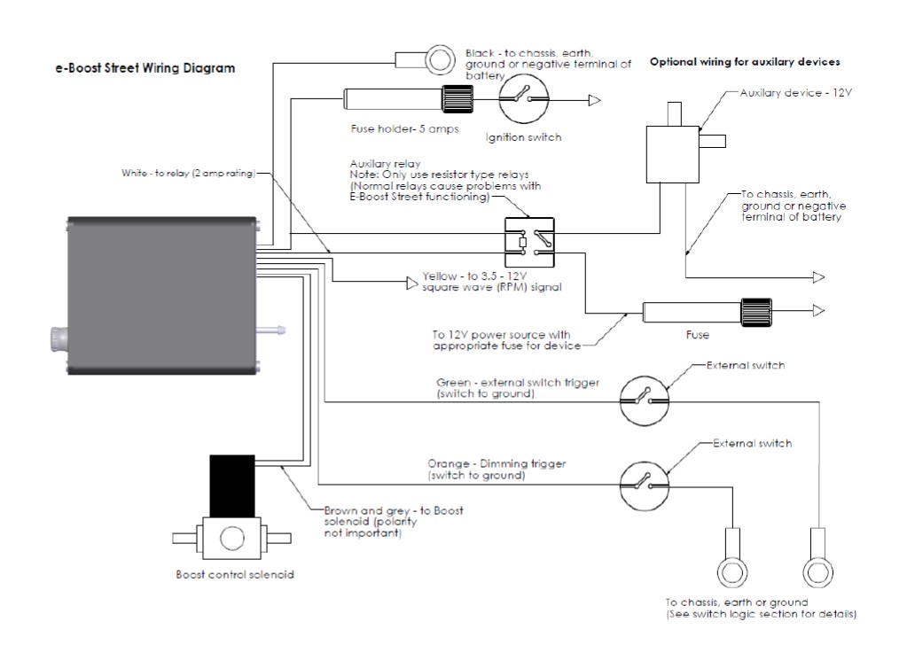
Wiring
(Solder all wires together and insulate the joints with the supplied heat shrink)
Note: Unused wires must be insulated with electrical tape so that they do not touch other wires or the chassis
Red Wire – 12 Volts switched through ignition – connect via 5 Amp fuse supplied
Black Wire – Chassis, earth or ground
Yellow Wire – To 3.5V – 12V Square wave (RPM) Signal OPTIONAL
Green Wire – External set point switching (Ground to activate) OPTIONAL
Orange Wire – Dimming trigger (Ground to activate) OPTIONAL
White Wire – Auxiliary Output (Negative switched) OPTIONAL
Brown and grey wire – to boost control solenoid (Polarity not important)
RPM Signal Connection (OPTIONAL)
RPM signal connection is ONLY for Tacho mode, RPM set point mapping, Boost correction, shift light function and other advanced features. Turbosmart recommends your RPM signal be connected by an appropriately qualified technician or automotive electrician. For further information consult your vehicle’s manuals or your local automotive electrician. The E-Boost Street is ONLY able to accept an RPM signal in the form of a square wave that is switching between 0V and 3.5-12 volts.
The following points should be followed to connect your RPM signal to an ECU pin.
- Locate your ECU RPM signal wire and splice into the signal wire coming from your ECU.
- Check the output you are splicing into is a square wave that is switching between switching between 0V and 3.5-12 volts with an
appropriate meter.
- Connect the yellow RPM wire from the E-Boost Street to the spliced section of the ECU RPM out.
- Turn on the E-Boost Street and configure your signal to the number of cylinders or rotors your engine has using the CYL (cylinder)
parameter located in the setup menu.
- In live mode with your engine running press mode once to show live RPM. The display should be reading RPMx100 e.g. 015 on
the display indicates 1500 RPM. If the display is not reading correctly re-check the cylinder configuration in the setup menu.
- Note: If the OEM tachometer does not display RPM after installing the E-Boost Street, a 2 ohm or higher resistor needs to
be installed in line between the ECU RPM output pin and the E-Boost Street.
The following points should be followed to connect your RPM signal to the negative terminal of an ignition coil. NOTE: Caution should be exercised when connecting to the negative terminal of an ignition coil and Turbosmart recommends an ECU connection where possible. IMPORTANT! The RPM signal should not be connected to a coil of a capacitive discharge ignition (CDI) system.
- Check the signal from the negative terminal is a square wave that is switching between switching between 0V and 3.5-12 volts with an appropriate meter. If the voltage is below 3.5V (coil trigger signals tend to have a very low voltage) the e-Boost will not read a signal. In this case, a signal amplifier (also known as a tach adapter) must be used to boost the signal.
- Connect the RPM signal wire from the E-Boost Street to the negative terminal of an ignition coil or tach adapter (which ever method is used).
- Turn on the E-Boost Street and configure your signal to the number of cylinders or rotors your engine has using the CYL (cylinder) parameter located in the setup menu
- In live mode with your engine running press mode once to show live RPM. The display should be reading RPMx100 e.g. 015 on
the display indicates 1500 RPM. If the display is not reading correctly re-check the cylinder configuration in the setup menu.
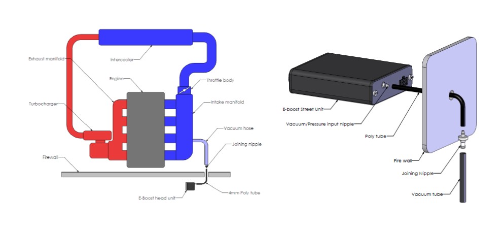
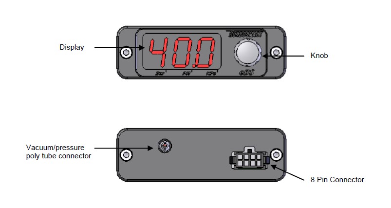
Vacuum/pressure signal
The E-Boost Street requires a vacuum/pressure signal from the intake manifold to function. A combination of poly tube and silicone hose is used to connect the E-boost Street to a adequate vacuum/pressure signal. Route the poly tube from the E-boost Street
head unit through the fire wall approximately 100mm (4”) only as the poly tube is not rated to the high temperatures of the engine bay.
Use the connecting barb to join the poly tube to the 3mm ID silicon hose at the firewall/bulkhead. Ensure the poly tube is pressed all the way onto the connecting barb
Route the silicon hose through the engine bay and connect it to a pressure/vacuum signal from the inlet manifold. Use the supplied tee piece if necessary.
Secure all connections with the supplied hose clamps
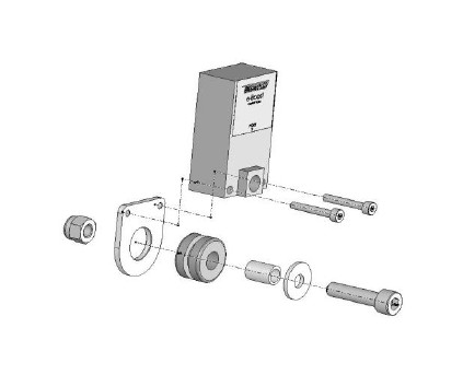
Installing the E-Boost Street Solenoid
- The E-Boost Street solenoid is rated to a maximum temperature of 100
degrees Celsius (212 degrees Fahrenheit), ensure that it is mounted a minimum of 250mm (10 Inches) away from the heat of the turbo or
exhaust manifold, otherwise heat shielding maybe required.
- Mount the E-Boost Street solenoid in an appropriate position in the
engine bay with the mounting kit supplied.
- Fit the rubber grommet inside the mounting plate. Slide the sleeve
inside the grommet. Use the M3 screws to bolt the solenoid to the
mounting bracket – Note use loctite on the threads to secure. Use the
M6 screw, washer and Nyloc nut to mount in a suitable location in the
engine bay.
- The E-Boost Street head unit is capable of controlling two solenoids. The use of twin solenoids is not necessary but is recommended in twin turbo setups on V configuration engines as this reduces the length of hose required for plumbing which aids
in response and control of the wastegates.
- The solenoid must be connected to a pressure only source which must be located before the intercooler, ideally off the compressor cover of the turbocharger. The air temperature before the intercooler is less affected by ambient conditions which will give you more consistent boost control.
SOLENOID HOOK UP METHODS
WARNING! Changing to different connection method can cause a higher than expected increase in boost pressure. Turbosmart recommends adjusting your boost controller back to its minimum setting and measuring the new minimum boost pressure achieved by the new setup before increasing your boost again.
Note: If your vehicle is fitted with a factory boost control solenoid, the hoses that run from the pressure source and to the wastegate actuator must be disconnected. Leave the solenoid plugged into the wiring loom so that the ECU is not affected. Failure to disable the factory boost control solenoid and hoses will result in erratic or fluctuating boost pressures which could damage your engine.
INTERNAL WASTEGATE CONNECTION
WARNING! Changing to different connection methods can cause a higher than expected increase in boost pressure. Turbosmart recommends adjusting your boost controller back to its minimum setting and measuring the new minimum boost pressure achieved by the new setup before increasing your boost again.
Note: If your vehicle is fitted with a factory boost control solenoid, the hoses that run from the solenoid to the pressure source and to the wastegate actuator must be disconnected from the solenoid. Leave the solenoid plugged into the wiring loom so that the ECU is not affected.
Most factory turbocharged vehicles use an internal waste gate system to control boost pressure. The E-Boost Street controls boost pressure by controlling the pressure signal that the waste gate actuator receives from the turbocharger. Please note that the E-Boost Street cannot be used to obtain a boost pressure lower than the standard waste gate actuator’s pressure setting.
Some factory hoses have a small restrictor fitted inside them, if the factory hoses are reused over boosting or boost spiking may occur.
Secure all connections with hose clamps.
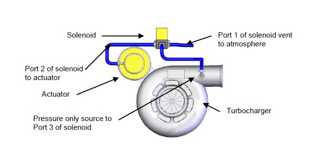
Single solenoid, single turbocharger hook up (Basic single internal wastegate setups)
Port (1): vents pressure from the solenoid. Connect this hose to the intake side of the turbo, between the air cleaner and the inlet of the turbocharger. Otherwise connect a short piece of the silicon hose and face the vent downwards to stop water or debris
entering the solenoid.
Port (2): to the internal wastegate actuator
Port (3): to pressure only source
If you are unable to achieve your desired boost pressure, it is normally due to exhaust manifold backpressure forcing the internal waste gate to open. To increase your boost pressure further, fit a higher pressure waste gate actuator to increase your minimum boost pressure.
WARNING! Fitting a higher pressure waste gate actuator may cause a higher than expected increase in boost pressure.
Turbosmart recommends resetting the boost set point values to Zero and measure the new minimum boost pressure before increasing your boost set point values.
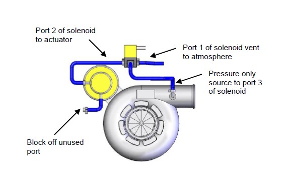
Internal wastegates with 2 ports
Port (1): vents pressure from the solenoid.
Port (2): connect to one of the ports of the actuator
Port (3): to pressure only source
Block off unused port on the actuator with suitable blank
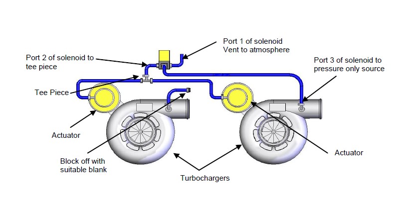
Single solenoid, twin parallel turbocharger hook up
(For straight configuration twin parallel turbocharger engines E.g. RB26DETT)
The E-Boost Street is capable of controlling twin internal wastegate turbochargers with a single solenoid.
This method is used when the turbochargers are mounted close to each other allowing the solenoid to be mounted close to both actuators
Each solenoid port is connected as follows:
-Port (1): vents pressure from the solenoid. Connect this hose to the intake side of the turbo, between the air cleaner and the inlet of the turbocharger. Otherwise connect a short piece of the silicon hose and face the vent downwards to stop water or debris entering the solenoid.
-Port (2): to tee piece that feeds both actuators
-Port (3): to pressure only source
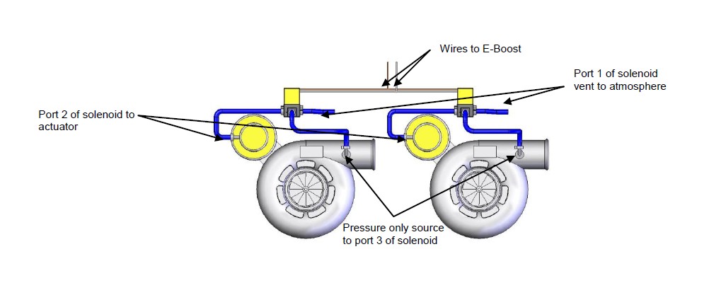
Twin solenoid, twin parallel turbocharger hook up
(For V configuration twin parallel turbocharger engines E.g. V6, V8 etc)
The E-Boost Street is capable of controlling two solenoids for twin parallel turbocharger setups.
This method is used when there is a great distance between the wastegates. This allows the solenoids to be mounted close to the wastegates to minimise the length of hose used and to maximise response
You will need a second solenoid for this method (TS-0301-3003)
Connect the grey wire from the e-Boost wiring loom to one of the wire from each solenoid.
Connect the brown wire from the e-Boost wiring loom to the remaining wire from each solenoid.
Each solenoid port is connected as follows:
-Port (1): vents pressure from the solenoid. Connect this hose to the intake side of the turbo, between the air cleaner and the inlet of the turbocharger. Otherwise connect a short piece of the silicon hose and face the vent downwards to stop water or debris entering the solenoid.
-Port (2): to the internal wastegate actuator
Port (3): to pressure only source
Port 2 of solenoid to actuator
EXTERNAL WASTEGATE CONNECTION
The first method of installation is a one port connection. If the desired boost level is not achieved i.e. boost level is too low, or not controllable, it is recommended that the wastegate spring be changed to a spring which is closer to the desired boost pressure or to trial a 2 port connection method.
There are 3 different 2 port connection methods that can be trialled to achieve different results. The 2 port method (1) can be used if there is high exhaust manifold back pressure forcing the valve open. The 2 port method (2) allows the user to achieve the maximum boost pressure their turbo system is capable of. If a wide range of boost pressures is desired i.e. 5 - 40 PSI, the 2 port method (3) with a 4 port solenoid (sold separately - TS-0301-2003) might be needed.
A single solenoid can be used to control twin wastegates in a twin turbo setup but it is recommended that twin solenoids are used in twin turbo setups to reduce the length of the pressure hoses to aid in control and response of the wastegates.
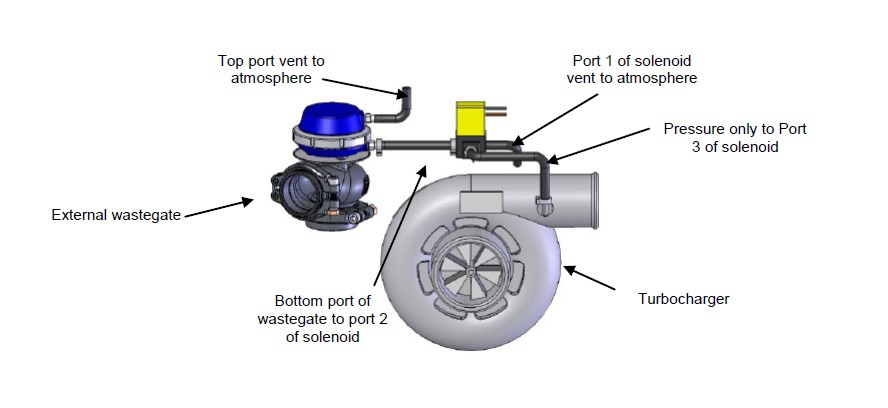
Single port, single solenoid, single turbo connection Method
(Basic single wastegate setup)
Port 1 of solenoid vent to atmosphere
Port 2 of solenoid to bottom port of wastegate
Port 3 of solenoid to Pressure only source
Single port, single solenoid, twin turbo connection Method
(For straight configuration twin parallel turbocharger engines E.g. RB26DETT)
Port 1 of solenoid vent to atmosphere
Port 2 of solenoid to bottom port of wastegate
Port 3 of solenoid to Pressure only source
Block off other turbocharger pressure port (if needed)
Single port, twin solenoid, twin turbo connection Method
(For V configuration twin parallel turbocharger engines E.g. V6, V8 etc)
Port 1 of solenoid vent to atmosphere
Port 2 of solenoid to bottom port of wastegate
Port 3 of solenoid to Pressure only source
Join the wires from both solenoids together (polarity not important) and then connect them to the brown and grey wires of the wiring loom
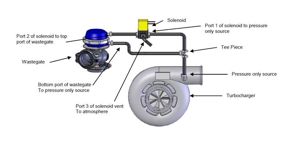
Two port, single solenoid, single turbo connection Method (1)
(For controlling boost on a single turbo, single wastegate, single solenoid turbo system with high back pressure)
*NOTE: An increase in your minimum boost pressure is expected when using any of the 2 port connection methods. Ensure all boost set point values and gate pressure values are set to Zero and measure the new minimum boost pressure achieved by this method before increasing your Boost Set Point values.
Connect the bottom port of the wastegate and Port 1 of the solenoid to a Pressure only source via a tee piece
Port 2 of the solenoid to the top port of the wastegate
Port 3 of solenoid vent to atmosphere
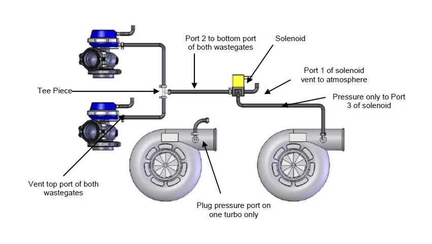
Two port, single solenoid, twin turbo connection Method (1)
(For controlling boost on a twin turbo, twin wastegate, single solenoid turbo system, on a straight configuration engine with high back pressure)
Connect the bottom port of the wastegates and Port 1 of the solenoid to a Pressure only source via tee pieces
Port 2 of the solenoid to the top port of the wastegates via tee pieces
Port 3 of solenoid vent to atmosphere
Block off other turbocharger pressure port (if needed)
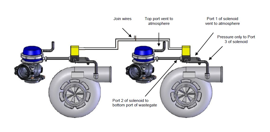
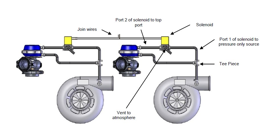
Two port, twin solenoid, twin turbo connection Method (1)
(For controlling boost on a twin turbo, twin wastegate, twin solenoid turbo system, on a V configuration engine with high back pressure)
Connect the bottom port of the wastegate and Port 1 of the solenoid to a Pressure only source via a tee piece
Port 2 of the solenoid to the top port of the wastegate
Port 3 of solenoid vent to atmosphere
Join the wires from both solenoids together (polarity not important) and then connect them to the brown and grey wires of the wiring loom
Two port, single solenoid, single turbo connection Method (2)
(For obtaining maximum boost pressure on your single turbo system)
Port 1 of solenoid to Top port of wastegate
Port 2 of solenoid to Pressure only source
Port 3 of solenoid to Bottom port of wastegate

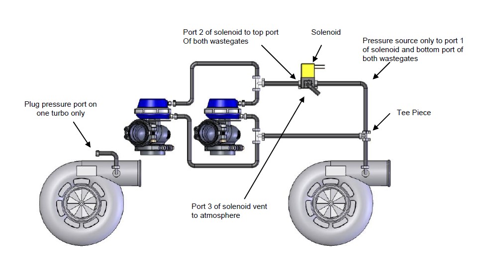
Two port, single solenoid, Twin turbo connection Method (2)
(For obtaining maximum boost pressure on your twin turbo straight engine)
Port 1 of solenoid to Top port of wastegates
Port 2 of solenoid to Pressure only source
Port 3 of solenoid to Bottom port of wastegates
Block off other turbocharger pressure port (if needed)

Two port, twin solenoid, Twin turbo connection Method (2)
(For obtaining maximum boost pressure on your twin turbo V configuration engine)
Port 1 of solenoid to Top port of wastegates
Port 2 of solenoid to Pressure only source
Port 3 of solenoid to Bottom port of wastegates
Join the wires from both solenoids together (polarity not important) and then connect them to the brown and grey wires of the wiring loom

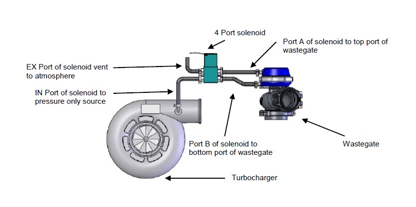
Two port, single 4 port solenoid, single turbo connection Method (3)
(For obtaining a wide range of boost pressures e.g. 5 - 40 PSI. This connection method has varying degrees of success depending on turbo system)
Port A of solenoid to Top port of wastegate
Port B of solenoid to Bottom port of wastegate
EX port of solenoid vent to atmosphere
IN port of solenoid to Pressure only source
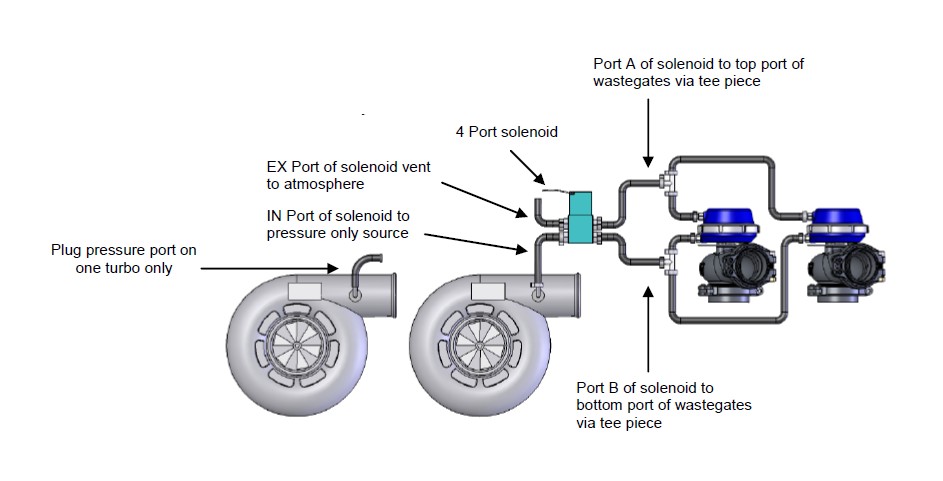
Two port, single 4 port solenoid, twin turbo connection Method (3)
(For obtaining a wide range of boost pressures e.g. 5 - 40 PSI on a straight configuration engine. This connection method has varying degrees of success depending on turbo system)
Port A of solenoid to Top port of wastegates
Port B of solenoid to Bottom port of wastegates
EX port of solenoid vent to atmosphere
IN port of solenoid to Pressure only source
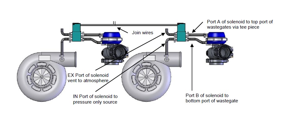
Two port, twin 4 port solenoid, twin turbo connection Method (3)
(For obtaining a wide range of boost pressures e.g. 5 - 40 PSI on a V configuration engine. This connection method has varying degrees of success depending on turbo system)
Port A of solenoid to Top port of wastegates
Port B of solenoid to Bottom port of wastegates
EX port of solenoid vent to atmosphere
IN port of solenoid to Pressure only source
Join the wires from both solenoids together (polarity not important) and then connect them to the brown and grey wires of the wiring loom
BASIC FUNCTIONALITYUnit Layout
OFF mode
The E-Boost Street can be switched off by holding the knob down for 10 seconds. This will disable the functionality of the E-Boost Street and result in wastegate spring tension boost levels. To turn the unit back on, press the knob.
Live mode menu
LIVE BOOST: Displays the amount of vacuum/boost being read by the unit.
LIVE RPM: Displays the RPM X100 (020 = 2000 RPM) of the engine if the RPM wire is connected to a Square wave signal from the ECU.
CURRENT SP VALUE: Displays the SP value the unit is currently set to.
PEAK HOLD BOOST: Displays the peak boost level the unit has measured.
PEAK HOLD RPM: Displays the peak RPM the unit has measured.
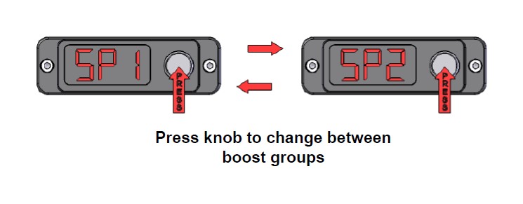
Changing between 2 boost groups
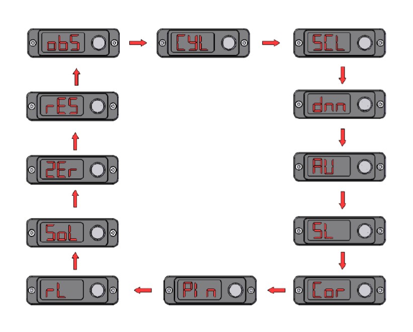
SETUP
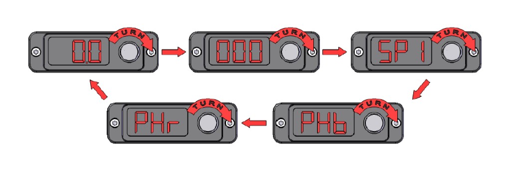
To enter the setup menu, press and hold the knob for 3 seconds. To navigate through the setup menu, rotate the knob to the left or right for the various options as shown below. To enter any of the menus, press the knob. Once your settings are entered via turning the knob left or right, you can save the setting by pressing the knob once. To exit any menu, press the knob for 3 seconds or alternatively, go to END in the menu. This will take you back to the previous menu.
OVER BOOST SHUTDOWN
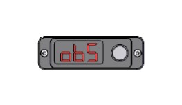
In order to successfully program your E-Boost Street you MUST carefully follow this section. Turbosmart recommends that this function is used in conjunction with another form of Over-boost protection such as fuel/ignition cut or over-boost valve. The OBS will not stop an over-boost scenario if there is a mechanical failure on the car that inhibits the E-Boost Street from controlling the wastegate or if electromagnetic interference due to incorrect wiring causes electrical interference to the E-Boost Street.
If the OBS is triggered the E-Boost Street will reduce the boost pressure to half of that set in the OBS parameter. Once this safe pressure is achieved the E-Boost Street will return to normal operation. OBS must be set to the maximum safe level your engine can handle and your set points must be below the OBS setting. When the OBS is triggered OBS will flash on the display to indicate that your boost pressure has reached the over boost shut down value. OBS will flash on the screen when triggered in live mode and when a set point is being edited. Please note, OBS will not work in setup mode.
The OBS is factory set to 7 PSI (0.48 Bar or 48 KPa), so you must enter a figure in order for the E-Boost Street to produce more than the standard boost pressure. The purpose of this feature is to protect your engine against accidentally entering a boost set point value that is too high, preventing a dangerously high boost pressure. Extreme care should be taken when setting this parameter. Turbosmart recommends that you seek advice from an appropriately qualified technician with regard to the OBS setting.
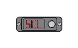
SCALE
The E-Boost Street readout can be configured in either Bar, PSI or KPa, the default setting is in psi. This allows you to tailor the readout to suit your own preference. Note that when the PSI scale is selected and the E-Boost Street is under vacuum conditions the display will read in inches of Mercury (inHg), not negative PSI.
BOOST SETUP (bG1 and bG2)
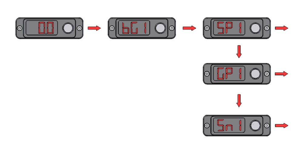
The E-Boost Street has the ability to control two levels of boost (BG1/BG2). The parameters that can be adjusted in each boost group are set point (SP1/SP2), gate pressure (GP1/GP2) and sensitivity (SN1/SN2). Set up the boost groups in the following order:
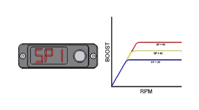
Setting SP1 (Set point): The SP value determines the DUTY CYCLE the solenoid will operate at when the gate pressure is reached. The SP value is not the amount of boost pressure your turbo will produce. This is a value between 0 - 99. The larger the value, the more boost the turbocharger will produce. Start the setup by increasing the SP value to 20. Bring the car onto boost and see what the maximum boost pressure is. Increase the value in small increments until you achieve your desired boost pressure. The SP value can also be adjusted while the car is on boost however, instead of the SP value being displayed, the boost pressure will be displayed so you know what pressure you are achieving. This is the easiest way to set your set points. Press the KNOB to enter the menu and adjust the values rotating the knob LEFT or RIGHT. Press the KNOB again to save the desired setting.
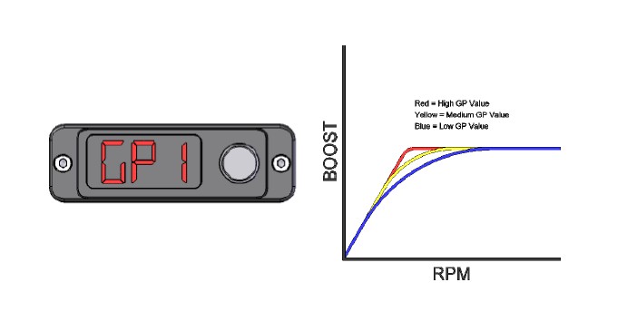
Setting GP1 (Gate pressure): This feature helps bring boost on faster at lower rpm and will give an increase in torque. Start by setting the gate pressure 5 PSI below the desired boost pressure with the corresponding SP value e.g. if the desired boost pressure is 15 PSI, set the gate pressure to 10 PSI first and adjust from there. Adjust the value higher to increase the response of the turbocharger or decrease the value to reduce the response. If this setting is too close to target boost, you will get a boost spike. Press the KNOB to enter the menu and adjust the values by rotating the knob LEFT or RIGHT. Press the KNOB again to save the desired setting.
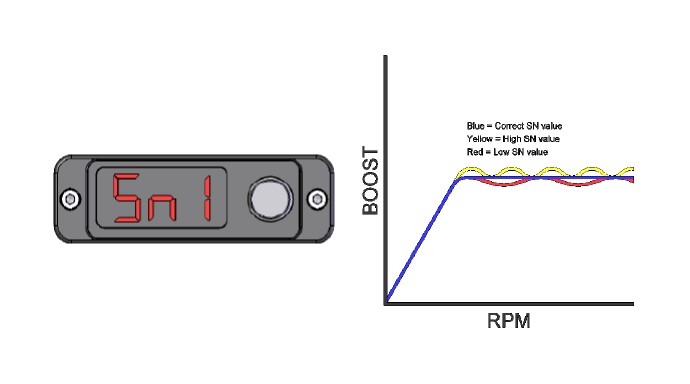
Setting SN1 (Sensitivity): The sensitivity is how sensitive the E-Boost Street is to changes in the boost curve. Under normal circumstances the sensitivity is left at the factory set level of 20. If your boost curve is wavy through the rev range, reduce the sensitivity, if your boost curve drops off at the end of the rev range, increase the sensitivity. Note: do not increase this value higher than 30. Press the KNOB to enter the menu and adjust the values by rotating the knob LEFT or RIGHT. Press the KNOB again to save the desired setting.
RPM DISPLAY CONFIGURATION
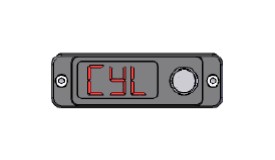
If you have connected the yellow RPM wire to an RPM signal from your ECU or negative terminal of an ignition coil you will need to input the number of cylinders / rotors in order to configure the RPM signal correctly i.e. the number of pulses per revolution being picked up from the RPM output of the ECU. The number of cylinders available is between 1 and 16. The RPM input can accept a square wave signal between 3.5 and 12V. For Mazda Rotary engines, 13B and 20B engines can be configured as 4 and 6 cylinders respectively.
LIGHT DIM
The brightness of the display can be adjusted on a scale of 0 - 6. The display can also be dimmed automatically by earthing the orange wire when the vehicle’s light system is switched on and setting the scale to 0.
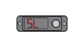
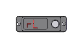
SWITCH LOGIC
The switch logic determines how the E-Boost Street switches between boost groups BG1 and BG2. It is factory set to internal switching (ISP) where boost groups are changed by pushing the knob. Alternatively, boost groups can be switched remotely when the switch logic is set to external switching (ESP). By earthing the green wire using a switch, you can toggle change from SP1 to SP2. Un-earthing this wire will return the set point back to SP1.
AUXILIARY OUTPUT
The e-Boost Street has an auxiliary output function designed to control an auxiliary device once a certain boost pressure or RPM value is reached i.e. water spray, water injection, warning light or nitrous controller. This circuit can be used to control a resistor type automotive relay with a maximum current draw of 2 amps.
There are four options bOn, bOF, rOn and rOF. The boost setting on (bOn) and off (bOF) value will be entered in the units that are currently selected for display. Between the bOn and bOF values the auxiliary output circuit will be closed and therefore will switch the relay on.
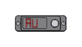
The RPM setting on (rOn), and off (rOF) are entered as RPM x 100 e.g. if 5000 RPM is the desired setting the user will input 050. Between the rOn and rOF values the auxiliary output circuit will be closed.
If the bOF or rOF is set to zero there will be no off and the circuit will remain closed until boost or RPM drops below the rOn or bOn value. If using a boost setting only to switch the relay the RPM parameter values should be set to zero to turn off or vice versa.
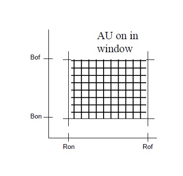
If using the auxiliary circuit as a nitrous controller, you can enter all four user definable parameters bOn, bOF, rOn, and rOF. The auxiliary circuit will be closed when boost and RPM fall with the window created by these four parameters. That is when boost pressure is between bOn and bOF AND when RPM is between rOn and rOF.
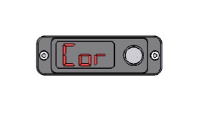
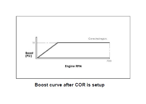
BOOST CORRECTION
This function is use to reduce or eliminate boost drop off at high RPM. Switching this function on will display the boost correction menu in the boost group menu. This function is best performed on a chassis dyno where the graph of the boost curve can be displayed and accurately interpreted.
The boost correction function requires 3 parameters to work; the START RPM, the END RPM and the correction factor.
START RPM (RP1): This is the engine RPM at which boost begins to drop off.
END RPM (RP2): This is the engine RPM at which you want to turn off the boost correction function, normally set at redline.
Correction factor (FAC): The percentage at which boost is dropping off between the START and END RPM.
Example:
The following boost curve shows that between 5000 and 7000 RPM, the boost drops off from 15 PSI to 10 PSI.
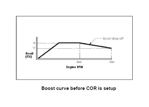
To reduce or eliminate this boost drop off, you need to input the following values:
RP1 = 050 (5000 RPM)
RP2 = 070 (7000 RPM)
FAC = 100 - [(10 ÷ 15) X 100] = 33
SECURITY PIN
The user or workshop can set a 3 digit password that will lock the boost menu, obS, SL, rSP, COR, dS, nSP, and CYL parameters for editing. The default code is 000 set from the factory. If the code has not been changed then the unit will be fully accessible and everything will be available for editing. As soon a different value is entered under the PIn parameter in the setup menu this will be the new password.
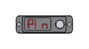
Once a password has been set under PIN in the setup menu pressing mode and down to access the boost menu will bring up a 3 digit prompt (triple zeros) where a PIN must be entered correctly to enter the boost group and unlock the unit. Once a password has been configured the obS, CYL, SL, rSP, COR, dS, nSP, in the setup menu will be masked and not available for editing. To unmask these parameters go to the PIn parameter and enter the current password to unlock the setup parameters for editing. Alternatively enter the correct PIN in the boost group prompt and the entire unit will be unlocked until the PIN is re-entered in the PIN parameter to re-lock the unit. Applying the factory reset will reset the code and reset all stored values to the factory defaults. This function enables workshops or tuners to lock their setup against tampering. Returning the PIN to 000 will de-activate the password protection.
RPM SHIFT LIGHT
This function allows the user to preset a RPM value at which the display will begin to flash. The RPM will continue to flash until the engine RPM drops below the preset value. RPM values are entered in multiples of 100, e.g. 5000 RPM = 050. The yellow wire needs to be connected as per the wiring diagram.
ZERO DISPLAY
The E-Boost Street is factory calibrated to read zero at standard atmospheric pressure and temperature. The E-Boost Street is altitude compensated however a large change in temperature can cause the display to read slightly above or below zero even when there is zero pressure applied to the E-Boost Street. This function allows you to zero the E-Boost Street display. IMPORTANT! Before using the zero function ensure the vacuum/pressure line is removed from the back of the unit.
SOLENOID CYCLE
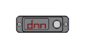
This function is used to check whether the solenoid is properly connected to the head unit. Selecting this function will cause the solenoid to cycle (click) 4 times.
FACTORY RESET
This function performs a factory reset and returns all the settings back to factory default. Be sure that you have written down the settings that you wish to keep before performing this function.
TROUBLESHOOTING
The following points should be checked if you find that your engine is over-boosting, under-boosting or the boost pressure is fluctuating erratically. Please note the following checks will cure 99% of problems experienced when fitting a Turbosmart E-Boost Street.
- Check that the E-Boost Street solenoid is installed correctly.
- Ensure the factory boost control solenoid is not connected in the hose between the pressure source and the wastegate actuator
- Ensure the length of the waste gate actuator rod has not been modified, refer to the manufactures specifications
- Check to see if the E-Boost Street solenoid is not blocked or contaminated with dirt, oil build up or debris
- Check the joining hoses for splits, cracks or loose connections and ensure they are not blocked, kinked or restricted, particularly if
the existing hose was reused
- Pressure test the waste gate actuator for leakage, the diaphragm or housing may be cracked or split
- Ensure the smooth and free operation of the wastegate arm in the turbo exhaust housing.
- Check that the hose between the E-Boost Street and the inlet manifold is not obstructed, broken or kinked.
- Check that the OBS is set higher than the boost pressure you are aiming for.
- Check the Blow-off Valve for leakage, some are used as over-boost valves
- Gate pressure maybe set too close to your desired boost pressure
- Ensure correct sensitivity setting.
- Check to see you can achieve constant steady boost with only the wastegate actuator connected directly to the pressure only
source on the turbocharger.
- Use the Solenoid check function to determine whether the solenoid is electrically connected to the head unit.
