 FREE 1 to 3-Day Delivery on Orders $149+ Details
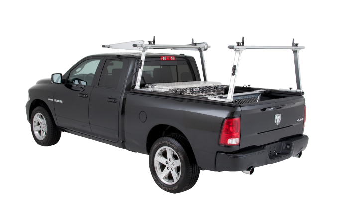
How to Install TracRac G2 Sliding Truck Rack on your F-150
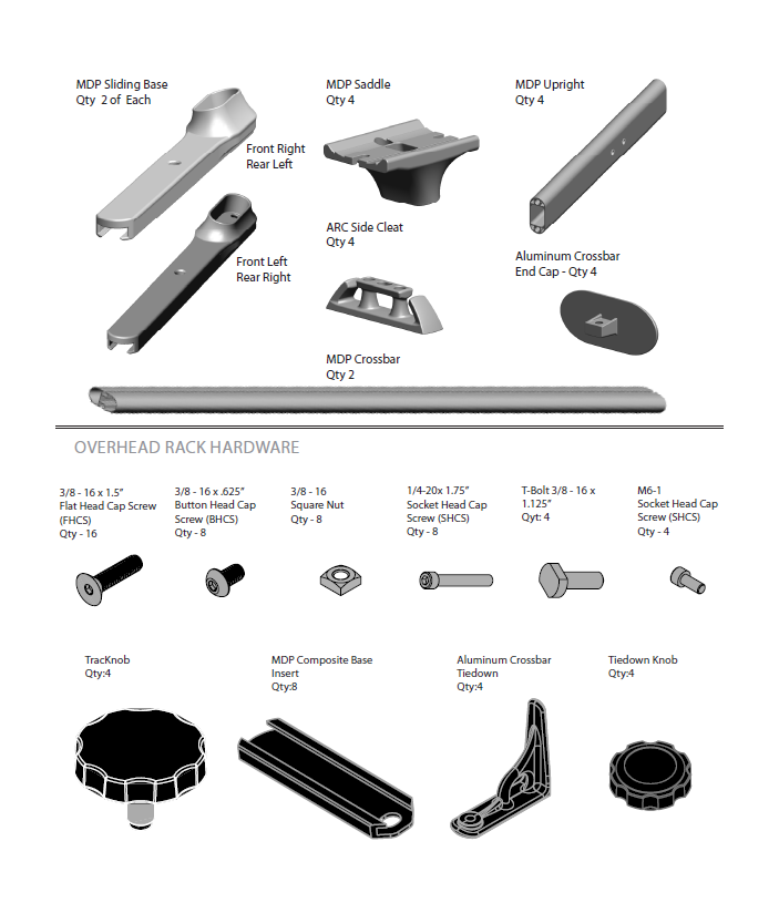
OVERHEAD RACK COMPONENTS
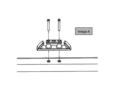
CLEAT ASSEMBLY:
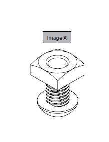
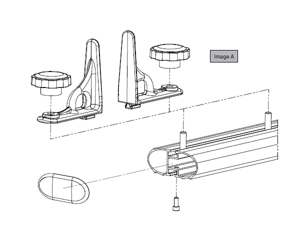
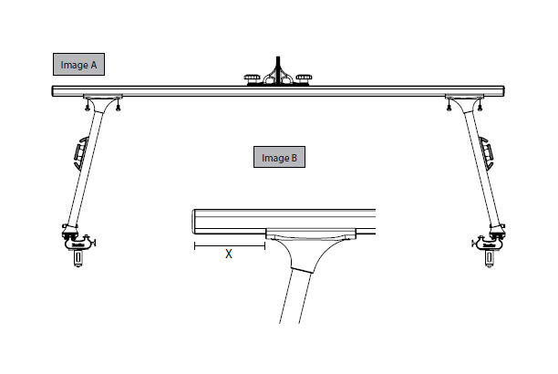
1. Line the Cleat up over the rivet nut and bolt to the upright using the 1/4-20x 1.75” Socket Head Cap Screw (SHCS). See Image A
2. Torque to 6 ft-lbs. using 3/16 Allen Key.
3. Repeat for the remaining uprights (4 Total)
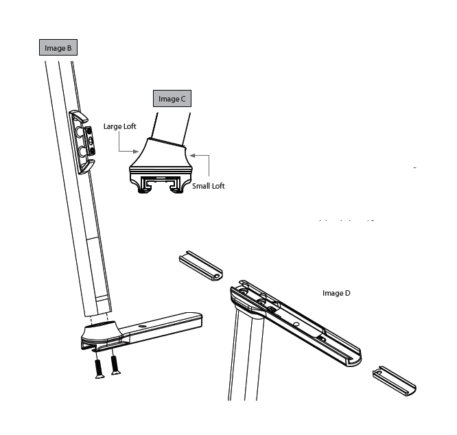
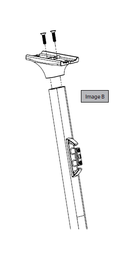
1. Insert the decal-end of the MDP Upright into the MDP Sliding Base.
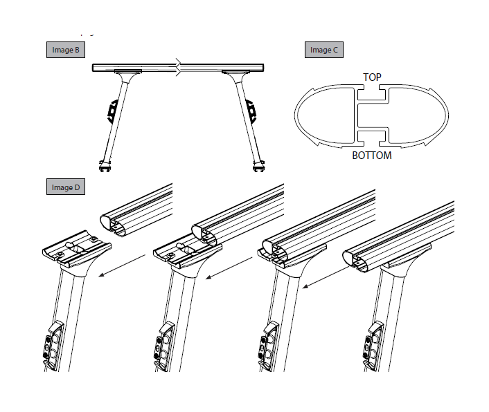
Important Note: Please make sure that the cleats are facing the larger loft of the base unit. See Image B (To double check, see Image C on the next page.)
2. Bolt the MDP Sliding Base to the MDP Upright using Two 3/8 - 16 x 1.5”(FHCS). Making sure the tool is fully inserted into the bolt, tighten using a 7/32 Allen Key.
Important Note: TracRac has intentionally made the tolerance between the bolt and the thread tight for maximum performance - Please hand-thread the bolts for the first few turns to ensure that proper engagement is achieved. You may also experience the need for additional force once the pink material engages the thread. This pink material is an assembly activated Loc-Tite that will ensure the rack does not need to be retorqued once installed.
3. Torque FHCS to 32 ft-lbs.
4. Insert the Composite Base Sliders (hole end first) into the MDP Sliding Base until they click into place. 2 Per Base See Image D
5. Repeat for the remaining uprights.
SADDLE ASSEMBLY:
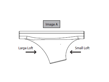
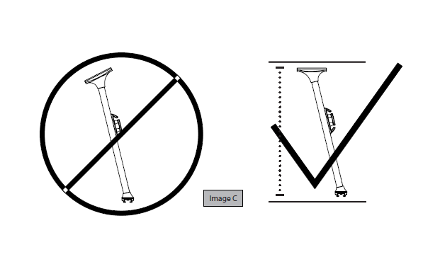
1. Insert the non-decal end of the upright in the saddle unit. Important Note: Please make sure that the small loft is facing the cleat side of the upright. (To double check, place the slider flat on the floor with the upright standing upwards. When the saddle is installed correctly the top of the saddle unit will be parallel to the floor.) See Image A & C
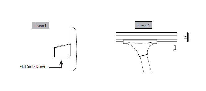
2. Bolt the MDP Saddle to the MDP Upright using Two 3/8 - 16 x 1.5”(FHCS). Tighten using a 7/32 Allen Key. Please note the guidelines from Base Assembly Step 2. See Image B
3. Repeat for the remaining three uprights Important Note: If you are installing a Cantilever Extension refer to those instructions before assembling all of the saddles.
CROSSBAR ASSEMBLY:
1. Pre-Thread the 3/8 - 16 x .625” (8) Button Head Cap Screw (BHCS) and the (8) Square Nuts with a ¾ turn and set aside. See Image A
2. Group together one right/left upright pair, a MDP Crossbar, and 4 of the BHCS/Square Nut pairs. See Image B
Note: When standing the racks right to left should angle towards one another; and front to back the elongated end of the sliders should be facing one another.
3. Take 2 of the BHCS/Square Nuts, with the square nuts facing up and place one into each of the slots of the MDP Saddle.
4. Take one of the MDP Crossbars and orientate the bar so that the bottom is facing the floor. See image C. Holding the bolts in the slots of the saddle slide the square nuts into the bottom T-Slot of the crossbar. See Image D
5. Do not tighten the bolts until step 5, repeat on the opposite side and the remaining pair of uprights.
TIEDOWN & ENDCAP ASSEMBLY:
1. Remove the Aluminum Crossbar Tiedowns from the bubble wrap and locate 4 T-bolts and Tiedown Knobs.
2. Insert the T-bolt through the hole of the tiedown and loosely secure with the knob.
3. Slide the unit into the top track of the crossbar and twist the knob until securely in place.
4. Next locate the Aluminum Crossbar End Caps. Making sure the flat side of the end cap is facing towards the ground, insert the end cap into the crossbar and secure using the M6-1 Socket Head Cap Screw (SHCS). Tighten using a 3/16 Allen Key.
TRUCK INSTALLATION:
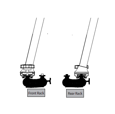
1. Take one of the two racks (Front Rack - towards the cab) assemblies and slide the unit onto the outside track of the base rails. Take the other rack (Rear Rack - towards the tailgate) and slide onto the inside track. Once in place, insert the male knob into the slider and tighten until the saddle is parallel to the ground.
2. Once on the vehicle, starting with two bolts on the inside of the rack, tighten the BHCS securing the crossbar to the saddles.
3. Torque BHCS to 27 ft. lbs. using the 7/32 Allen Key.
Note: You will want to make sure that the crossbar is centered on the vehicle. To do this, measure from the tip of the crossbar to the saddle. Ensure that dimension X is the same on both sides of the crossbars.
4. Loosen the male knobs in the slider to ensure that both racks slide smoothly on the base rails. NOTE: If the racks are not sliding: Double check to make sure your base rails are parallel and square. Check the sliders and make sure they are centered on the t-tracks of the base rails - if they are hitting the track on one side or the other, adjust the saddle/crossbar connection to ensure an even disposition of the rack relative to the base rails.
GENERAL USE & CARE:
Please read the following guidelines - it is very important that you follow these instructions to ensure your rack continues to function properly and to ensure your product remains covered under the TracRac Limited Lifetime Warranty.
• KNOBS: The knobs on your TracRac are made from stainless steel. To prevent them from seizing up (especially in the winter), 1-2 times/season, remove all 4 of the TracKnobs from the Sliding Base and clean any buildup on the threads with a piece of Scotch-Brite™or similar abrasive cloth. After the threads are clean, spray the threads of the knobs and the threads of the base with WD-40®, Never-Seize type lubricant or similar anti-seize lubricant. (Common household Vaseline can suffice).
• TIEDOWNS: Make sure tiedowns knobs are secured properly before securing any load to the rack.
• ELECTRICAL: When mounting lights or other electrical systems to your TracRac, do not use any component of the system as a ground or to carry an electrical current. Always run 2 wires to the electrical unit - One positive lead to the switch for power and one ground lead to the frame of the vehicle. Make sure the power lead has an appropriate size fuse.
• LOAD RATING: TracRac G2 is capable of carrying a maximum of 1250 lbs., evenly distributed when configured with the rear rack mounted on the inner track and both racks at opposite ends of the base rails.
• SAFETY: For good performance and safety, periodically check that the base rails remain parallel and secure. Re-torque all fasteners to the proper specifications after the first 500 miles and every 10,000 miles thereafter. Lubricate the threaded portion of all knobs every 2000. Carrying heavy loads over rough roads with excess speed may damage the system. Always properly secure all cargo. Exercise good judgment at all times.

