 FREE 1 to 3-Day Delivery on Orders $149+ Details
How to Install SuperLift 2 in. Front Leveling Kit on your F-150

Shop Parts in this Guide
INSTALLATION INSTRUCTIONS
INTRODUCTION
Installation requires a professional mechanic. Prior to beginning, inspect the vehicles steering, driveline, and brake systems, paying close attention to the control arms and bushings, anti-sway bars and bushings, steering linkage, ball joints and wheel bearings. Also check the steering sector-to-frame and all suspension-to-frame attaching points for stress cracks. The overall vehicle must be in excellent working condition; repair or replace all worn parts.
Read instructions several times before starting. Be sure you have all needed parts and know where they install. Read each step completely as you go.
NOTES:
• Prior to beginning the installation, check all parts and hardware in the box with the parts list below. If you find a packaging error, contact Superlift® directly. Do not contact the dealer where the system was originally purchased. You will need the control number from each box when calling; this number is located at the bottom of the part number label and to the right of the bar code.
• Front end realignment is necessary.
• A foot-pound torque reading is given in parenthesis ( ) after each appropriate fastener.
• Do not install any additional components or modify this system to gain additional suspension height.
• Prior to attaching components, be sure all mating surfaces are free of grit, grease, undercoating, etc.
• Speedometer recalibration is recommended if a taller tire is used.
• A factory service manual should be on hand for reference.
• Use the check-off box “” found at each step to help you keep your place. Two “” denotes that one check-off box is for the driver side and one is for the passenger side.
DISASSEMBLY
NOTE: Save all factory components and hardware for reuse.
1) PREPARE VEHICLE... Place vehicle in neutral. Raise front of vehicle with a jack and secure a jack stand beneath each frame rail, behind the lower control arms. Ease the frame down onto the stands, place transmission in low gear or “park”, and chock rear tires. Remove front tires.
2) BRAKE HOSES… Remove the bolt securing the rubber brake hose-to-frame.
3) ANTI-SWAY BAR… The anti-sway bar links connect the bar body to the lower control
arms. On each side, disconnect the links from the bar body.
NOTE: Steps 4 through 12 are performed one side at a time.
4) AXLE SHAFTS… Remove the bolts securing the axle shaft to the differential flange.
5) TIE-ROD ENDS… Remove the nut securing the tie rod end to the knuckle. Using the appropriate puller tool, separate the tie rod end from the knuckle.
6) CONTROL ARM BOLTS…
IMPORTANT: Eccentric cam bolts connect the lower control arm-to-frame, and are also used for front end alignment. In later steps the eccentrics must be restored to their pre-lift position for alignment to be “in the ball park” prior to final alignment. Prior to loosening, scribe a line on each eccentric washer, and the flanges they contact, for later reference.
Loosen, do not remove, all four control arm-to-frame bolts (both upper and lower control arms).
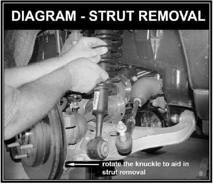
7) COIL STRUT REMOVAL… [SEE PHOTO]
Mark the position of the coil struts so that they can be installed on the appropriate side and orientation during reassembly.
Support the lower control arm with a floor jack. Remove the bolt that attaches the strut-to-lower control arm. NOTE: 2014 model vehicles have a bar pin in the lower strut mount with two bolts going through the lower control arm. Remove the two nuts and proceed following the instructions. Remove the three nuts securing the strut assembly-to-frame.
Remove the nut securing the upper ball joint-to-knuckle. Using the appropriate puller tool, separate the ball joint from the knuckle.
While holding the top of the knuckle, lower the control arm enough to facilitate removing the strut assembly.
NOTE: When removing the strut, it is helpful to rotate the knuckle to gain clearance between the lower strut mount and axle shaft.
ASSEMBLY
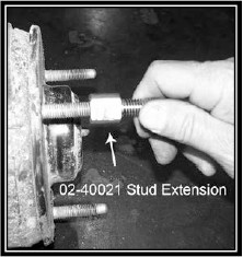
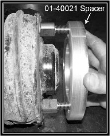
8) STUD EXTENSIONS AND STRUT SPACER…
Using the appropriate cutting tool cut 5/16” off of the factory stud length. Clean the threads after cutting.
[SEE PHOTOS] Thread the stud extensions (SL#02-40021) onto the factory studs (35). Position the strut spacer (SL#01-40021) over the stud extensions.
Mate the strut assembly’s upper end to its frame mount; align the scribe marks made in step 7. Secure with the supplied 7/16” flange nuts, snug but do not tighten.
Raise the lower control arm, and attach the bottom of the strut assembly-to-lower control arm using the factory hardware. Do not tighten at this time. This may require loosening of the upper strut flange nuts.
9) BALL JOINTS, TIE RODS… Reattach the upper ball joint-to-knuckle (85). Attach tie rod end-to-knuckle (111).
10) AXLE SHAFTS… Line the axle shaft up with the differential flange, and secure using the factory hardware (60).
11) ANTI-SWAY BAR… Connect the sway bar end link to the sway bar
11) ANTI-SWAY BAR… Connect the sway bar end link to the sway bar body using the factory hardware (98).
12) BRAKE HOSES… Reattach the rubber brake hose-to-frame and secure using the factory hardware.
Repeat steps 4 through 12 on opposite side.
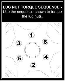
13) TIRES / WHEELS... [SEE DIAGRAM] Tighten the lug nuts (150) in the sequence shown.
WARNING: When the tires / wheels are installed, always check for and remove any corrosion, dirt, or foreign material on the wheel mounting surface, or anything that contacts the wheel mounting surface (hub, rotor, etc.). Installing wheels without the proper metal-to-metal contact at the wheel mounting surfaces can cause the lug nuts to loosen and the wheel to come off while the vehicle is in motion.
WARNING: Retighten lug nuts at 500 miles after any wheel change, or anytime the lug nuts are loosened. Failure to do so could cause wheels to come off while vehicle is in motion.
14) INITIAL CLEARANCE CHECK... With the vehicle’s frame rails still on jack stands, and the suspension “hanging” at full extension travel, cycle steering lock-to-lock and check all components for proper operation and clearances. Pay special attention to the clearance between the tires / wheels and brake hoses, wiring, etc.
15) TIGHTEN REMAINING FASTENERS…
Lower vehicle to the floor. The suspension is now supporting vehicle weight. On each side, tighten:
2009-2013 Strut assembly-to-lower control arm (351).
2014 Strut assembly-to-lower control arm (70).
Strut assembly-to-upper tower (40).
Upper control arm-to-frame (114).
Lower control arm-to-frame (259). Prior to tightening the lower control arm eccentric cam bolts, align the scribe marks made in step 6.
16) FINAL CLEARANCE CHECK... Cycle steering lock-to-lock and inspect the tires / wheels, and the steering, suspension, and brake systems for proper operation, tightness, and adequate clearance. Pay close attention to knuckle and tire / wheel clearance.
17) HEADLIGHTS... Readjust headlights to proper setting.
18) SUPERLIFT® WARNING DECAL… Install the WARNING TO DRIVER decal on the inside of the windshield, or on the dash, within driver’s view. Review the “IMPORTANT PRODUCT USE AND SAFETY INFORMATION / WARNINGS” text found at the end of this instruction sheet.
19) ALIGNMENT... Realign vehicle to factory specifications.

