FREE 1 to 3-Day Delivery on Orders $149+ Details
How to Install Spectre Performance Cold Air Intake - Polished on your F-150
Installation Time
1 hours
Tools Required
- Ratchet
- 10mm wrench
- 10mm socket
- 8mm socket
- Socket extension
- 5/16” or 8mm nut driver

Shop Parts in this Guide
Parts List
1 – Heat shield 1
1 – Heat shield 2
1 - Air filter
1 - Intake tube
3 – 3.5” hose clamps
1 - 3” hose clamp
1 - Rubber seal 76cm
4 - M6 fender washers
2 - M6 lock nuts
2 - M6-1.0 x 25mm bolts
1- 3”-3.5” coupler
2 - Heat shield lower mounting spacer
2 - Heat shield upper mounting spacer
1 – Velocity stack adapter
1- 3.5”Flex coupler
3- Allen bolt
3- Flat washer
3- Locknut
1- Allen wrench
4- M6 Hex bolts
4- M6 Lockwasher
1- 3/4” Breather Hose 24cm
1- 3/4” Breather Hose 13cm
1- 5/8” Breather Hose 13cm
2- 30mm Hose clamps
2- 25mm Hose clamps
1- MAFS gasket
1- Grommet
Step 1
Safety first! Before you begin the installation, make sure that the vehicle is in park (or neutral for a manual transmission) with the parking brake set. Disconnect the negative battery terminal and verify that all components that are listed are present. Note: This kit was designed and tested on a stock engine without any custom tuning done to the engine computer. Removing the battery cable may erase the programmed radio stations. The anti-theft code will need to be entered into some radios after the battery cable is connected. The anti-theft code can typically be found in the owner’s manual or at your local dealership.
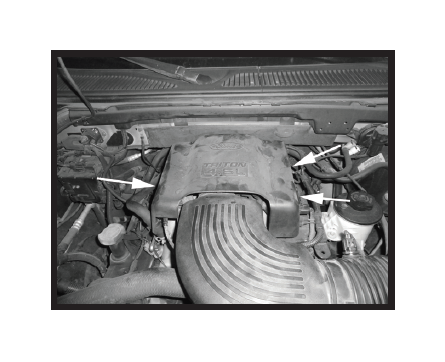
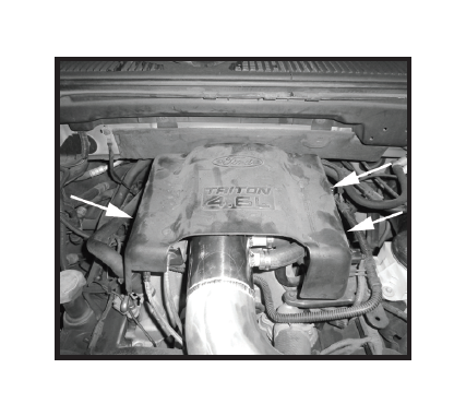
Step 2
Remove the three bolts securing the throttle body cover and remove.
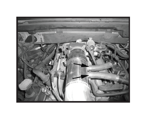
Step 3
On 4.6L engines, remove the idle air control hose and chamber from the vehicle. Disconnect the crankcase vent hose from the factory air intake tube.
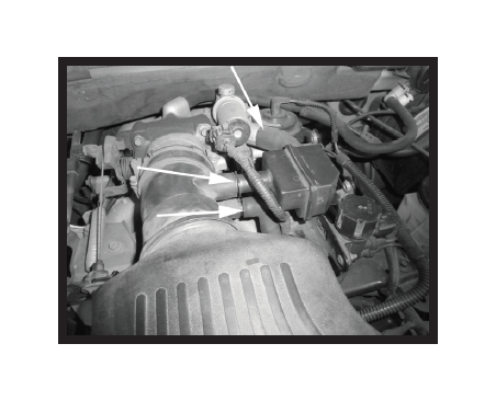
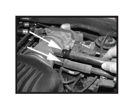
Step 4
On 5.4L engines, disconnect the crankcase vent hose and the idle air control hose from the factory air intake tube.
Step 5
Unclip the Intake Air Temperature (IAT) sensor wiring and unclasp the air filter latch.
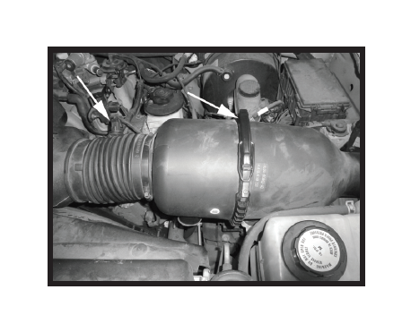
Step 6
Loosen the clamp at the throttle body.
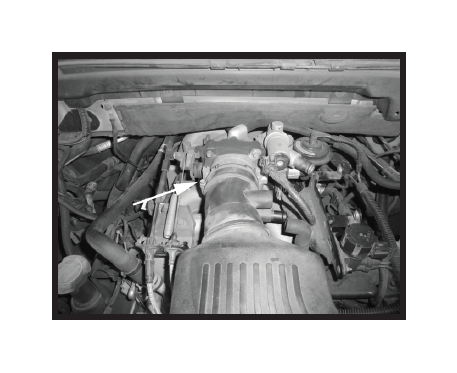
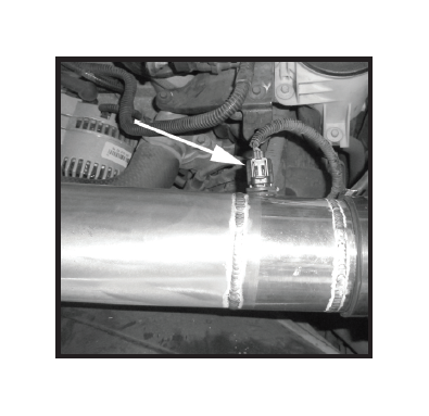
Step 7
Disconnect the Mass Air Flow Sensor (MAFS) from the harness and remove the assembly from the housing. Remove the factory air intake tube from the vehicle.
Step 8
Remove the air filter housing by lifting firmly upward.
Step 9
Remove the IAT from the factory air intake tube.

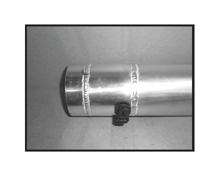
Step 10
Install the grommet into the tube, and then install the IAT sensor into the grommet.
Step 11
Remove the MAFS assembly from the housing.
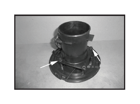
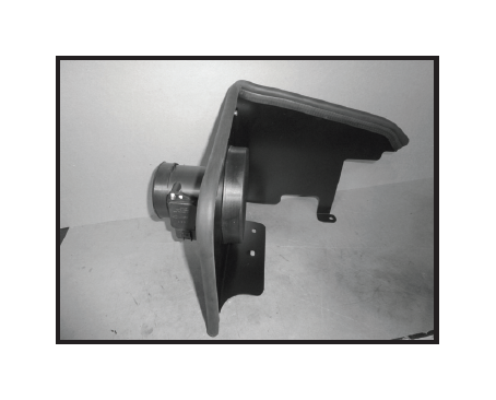
Step 12
Assemble the heat shield with the tabs placed on the outside of heat shield. Install the rubber bulb seal. Place the velocity stack adapter on the heat shield and install the MAFS placing the gasket between the heat shield and the MAFS. Once all of the holes are lined up, install the hardware and fasten securely.
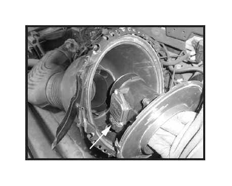
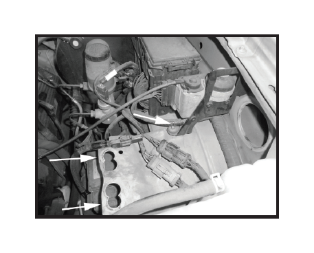
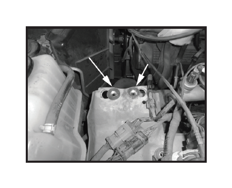
Step 13
Remove the two grommets from the vehicle and remove the bolt shown. This bolt will be reused in a later step.
Step 14
Install the heat shield upper mounting spacers as shown.
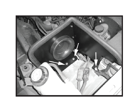
Step 15
Install the heat shield in location. Install the bolt and fender washer from the top side of the bracket. Install the lower mounting spacers and fasten securely in place with the supplied fender washer and nut. Install the bolt removed from Step 13.
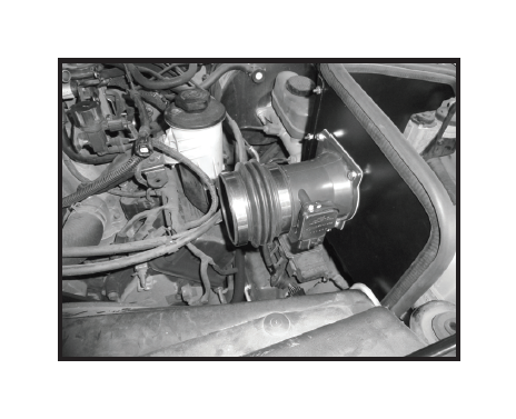
Step 16
Install the 3.5” flex boot on the end of the MAFS and fasten securely. Install the second clamp but do not tighten at this time.
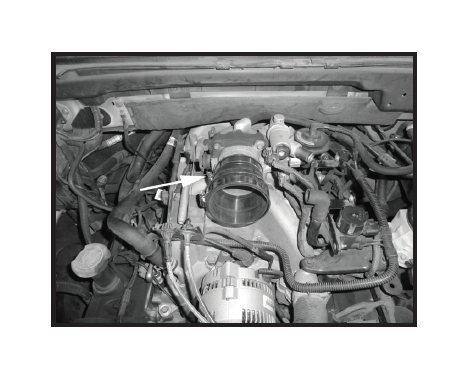
Step 17
Install the reducer coupler on the throttle body and fasten securely. Install the second clamp but do not tighten at this time.
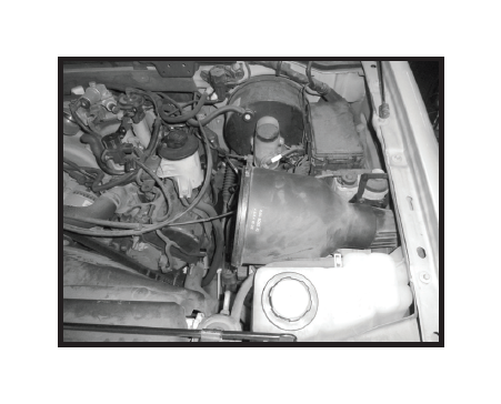
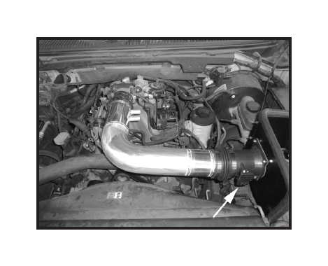
Step 18
Install the new air intake tube supplied in the kit. Once the tube is in the desired location, securely fasten all the couplers in place. Reconnect the MAFS electrical sensor.
Step 19
On 4.6L applications, install the factory crank case vent line onto the fitting and fasten securely with a clamp. Install the new idle air control hose supplied in the kit.
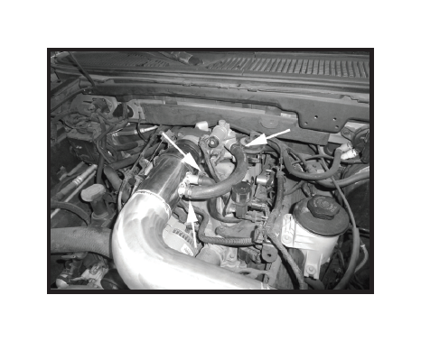
Step 20
On 5.4L applications, install the short 5/8” hose on the factory crank case vent line and onto the intake tube and fasten securely with the supplied clamps. Install the short 3/4” hose on the factory idle air control hose and onto the intake tube and fasten securely with the supplied clamps.
Step 21
Reconnect the IAT sensor wire.
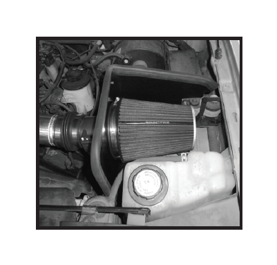
Step 22
Install the filter and fully tighten clamp.
Step 23
Reinstall the engine cover.
Step 24
Make sure that all clamps and hardware are fully tightened. Reconnect the battery cable, start the vehicle and let it warm up. Shut off and inspect the installation once more for any loose clamps, wires, or hardware. Test drive & enjoy! Your installation is now complete. Periodically check all clamps and brackets.