FREE 1 to 3-Day Delivery on Orders $149+ Details
How to Install Snow Performance Stage 2 MAF/MAP Water-Methanol Injection System on your Ram
Installation Time
3 hours
Tools Required
- Screw Driver
- 5/16 Open End Wrench
- 1/8” -27 NPT Tap
- Adjustable Wrench
- Utility Knife
- Electric Drill W/ Drill Bits
Installation- Mechanical
Step 1 Level Switch Install
• Locate desired level switch mounting position. Suggest placement is 1/3 of max reservoir height.
• Carefully drill side of reservoir using 13/16” bit. A step bit is recommended for best drilling results. Hole must be free of nicks or shavings for proper sealing.
• Remove rubber seal from level switch. Insert seal into reservoir until fully seated.
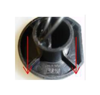
• Lubricate exterior of level switch with water and insert into seal until fully seated. Position level switch so GT symbol is at six o’clock position.
• With fluid level above level switch, float should be angled up. With fluid level below level switch, float should be in horizontal position.
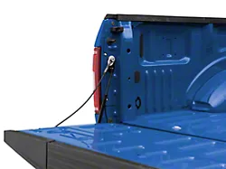
Step 2 Reservoir Install
• Install 3/8” NPT to ¼” tube reservoir fitting using E6000® sealant in the bottom of the reservoir.
• After allowing the thread sealant to dry, fill reservoir with about 1- quart of water and check for leaks around reservoir fitting and level switch. If leak occurs use E6000® sealant.
• Install the 3qt. reservoir with four (4) #8x1&1/2” screws and four (4) #8 washers in desired mounting location.
**The reservoir should be installed above the pump, but below the nozzle. This keeps the pump primed and avoids fluid leaking into nozzle when not in use**
**Use caution when installing screws, do not damage any wiring or fluid lines that may be hidden**
***Caution***
To avoid gravity feeding of fluid with rear mount reservoirs, it is essential to use a solenoid upgrade (Part #40060). Do not operate your rear mount reservoir equipped vehicle without a solenoid installed.
Step 3 Pump Install
• Position the fluid pump so that the inlet is positioned at or below the lowest point of the reservoir, and within two feet of the reservoir. (Pump can be installed in any orientation).
***Arrows on the pump inlet and outlet indicate the direction of fluid flow***
• Install the fluid pump with four (4) #8x1&1/2” screws and four (4) #8 washers.
• Using supplied large eyehook connect pump black wire to chassis ground.
• Remove the rubber plugs from the push-locks by first pushing the plug toward the pump, hold the grey collar against the pump, and gently pull the plug from the fitting.
***Pulling against the push-lock fittings with excessive force may cause damage to the fittings***
• Fit the high pressure tubing between the reservoir fitting and the pump inlet, ensuring there are no kinks in the line and there is no stress on the push-lock fittings.
***Kinked tubing and stressed fittings may cause fluid leaks***
• Cut tubing straight and remove burrs so that the fluid line properly seals against the internal o-rings.
• Insert tubing into the push-locks until fully seated, and pull lightly against push-locks to ensure proper installation.
***Caution***
Pump must be shielded from road debris and tire wash. Failure to do so will result in pump failure.
***Caution***
Prolonged quench may cause lower engine damage over a period of time.
Tuning Quick Reference
The power potential of the system is realized through increased boost and/or timing. The large gains on octane and cooling provided by the system make this possible, even on standard pump fuel.
The Snow Performance system adds an alternate fuel source as well as significantly cools combustion. With this, one does not need to cool combustion with overly rich air/fuel ratios. To minimize combustion quench, you should start with an air to fuel ratio of 12.0-12.5:1.
Injecting water/methanol lower than 3300-3500 RPM could result in combustion quench. All vehicles are different. If the engine bogs or loses power, then it is coming on too early, the quantity is too much, or there is not enough methanol in the mixture (50/50 water/methanol recommended).
Maintenance
Remove nozzle(s) and clean screen filters once per year using a calcium removing formula such as CLR®
The Boost Cooler® has been designed to operate with high concentrations of methanol. Oil or other additives are not required for system lubrication, and can cause damage to the system.
Contaminants in the fluid such as dirt can damage the system. Ensure that dirt and debris do not fall into the tank.
Do not use Teflon tape or paste to seal connections. These sealers are not as effective as the Goop sealant provided and can break down over time, clogging components.
For best performance, cooling, and system life it is recommend that Snow Performance Boost Juice™, part #40008, is the exclusive fluid used in the system.
For MAF voltage readings between the Start and Full settings, the controller will linearly adjust the pump output as shown on the graph. This insures accurate injection along all engine load states.
Note the chart on the controller itself. This shows what settings are associated with particular voltages and HZ values for the various modes available.
• Adjust the START level first by turning dial to the 12:00 position. This sets the MAF sensor output required to activate the injection system.
• Next, adjust FULL level to the air flow sensors max voltage or HZ output.
***Over lapping the settings, where the FULL dial is lower then START, will result in max injection at the onset point.***
• Road test vehicle and adjust FULL dial until a smooth power curve is felt with no misfiring. Often the full dial can be set lower than the max output of the MAF for more cooling. If any bucking or bogging is experienced, increase the full point until it is eliminated. If bucking is felt at the onset of injection, increase the start point.
TECH TIP: In most applications, the start dial should initially be set at the 12:00 position, so that typical airflow levels in normal driving do not trigger injection needlessly. The full dial should be all the way to the clockwise position. Start tuning by carefully trying lower start point settings. If bogging is experienced at the onset of injection, move the start dial back up a small amount. Then try lower and lower points for the full setting. If bogging is experienced as injection ramps up, turn the full point back up to a safe level. The engine should run with no bogging or miss-fires. Be sure to make small changes and then test them each time to avoid any drastic differences in injection.
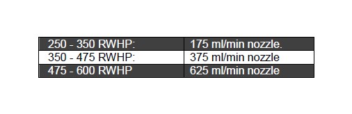
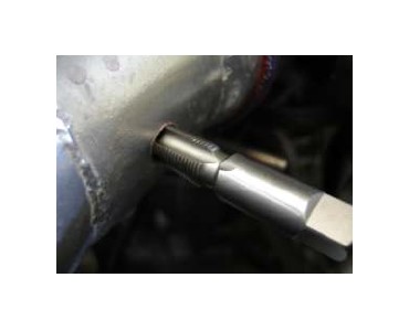
Step 4 Nozzle Selection
Nozzle sizing is determined by horsepower (which approximates the engine airflow) and boost (which approximates intake charge heat). Recommended starting points:
***The end of the nozzle with the fine mesh screen should be inserted into the nozzle holder***
• Using a 5/16” open end wrench and a 7/16” open end wrench, tighten the nozzle ½ turn past finger tight.
***Teflon sealants are not compatible with water/methanol, and should not be used with the install of your Snow Performance Boost Cooler***
TECH TIP: Seal the nozzle into the nozzle holder using the included E6000® sealant. Using a sealant that is not permanent will allow for nozzle changes during tuning. Simply remove the nozzle, clean the threads, and reinstall using sealant.
***Caution***
If nozzle is mounted lower than the reservoir or beyond the throttle body, a Solenoid (Part #40060) must be used to prevent gravity and/or vacuum siphoning.
Step 4 Nozzle Mounting
• Drill and tap the intake tube with a 11/32” drill bit and a 1/8”-27 NPT thread tap in desired nozzle mounting location.
***To prevent debris from entering the engine, remove the intake tube from the vehicle prior to drilling***
Note: If no metal piping is available to tap for nozzle placement a Nozzle Mount Adapter (Part #40110) may be used to secure nozzle in plastic/rubber air Inlet pipe.
TECH TIP: Install the nozzle within 6-inches of the throttle plate at a 90°angle to the direction of airflow, and so that the nozzle tip is flush with the inside of the intake tube or protruding slightly to ensure an uninterrupted spray pattern.
• Install the nozzle assembly into the threaded intake tube.
• Using a 5/16” open end wrench, tighten the nozzle assembly ½ turn past finger tight so that the nozzle head is flush with the inside of the intake tube.
• Re-install the vehicle’s intake tube into its proper mounting location.
***Caution***
Mounting the nozzle after the throttle body will cause siphoning due to engine vacuum. To prevent siphoning, a solenoid (Part #40060) must be installed.
• Remove the plastic plug on the front of the Boost Cooler® controller.
• Select the proper dip switch according to your vehicle’s MAF/MAP sensor signal output.
• After the switch has been selected, reinstall the plastic plug.
• Begin the testing process with both dials on the VC-MAFU at their highest settings (clockwise).
• Turn ignition key on so that the system has 12volt power. If the pump runs, inspect ground wires for secure connection and repair as needed.
• The Pump should be off at this point, start vehicle. Slowly turn the start dial lower (counter clock wise) until the pump activates. If the lowest setting is reached without pump activating, it may be necessary to rev engine to increase airflow signal to the controller.
• Turn Start dial back up (clockwise) until pump shuts off.
Initial Tuning
Variable Tuning Example
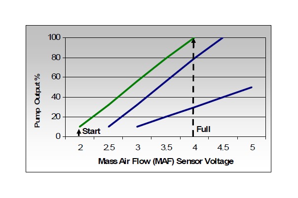
In this example the Start dial is set at 2 volts and the Full dial at 4 volts. At 2 volts from the MAF, the pump will operate at 10%. At 4 volts from the MAF, the pump will deliver 100% of injection pressure.
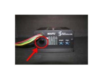
To access the MAF selector switch, remove the plastic plug located under the wire harness connector on the front of the VC-MAF. The default setting is all switches but 4 (right) in the OFF or UP position. This selects a 0-5 volt output type of MAF sensor.
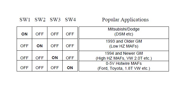
Note: Only one switch can be in the ON or DOWN position at a time. If more then one switch is in the ON position, the VC-MAF will not control injection properly.
TECH TIP: If you are unsure what type of mass air flow sensor you have contact your local dealership or mechanic who has access to All Data to find out exactly what setting you need for your Snow Performance injection system
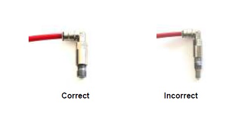
Step 6 Nozzle Connection
• Fit the high pressure tubing between the pump outlet and the nozzle assembly, ensuring there are no kinks in the line and there is no stress on the push-lock fittings.
• Cut tubing straight and remove burrs so that the fluid line properly seals against the internal o-rings.
• Insert tubing into the push-locks until fully seated, and pull lightly against push-locks to ensure proper installation.
**Tubing should connect to push-lock fittings at shallow angles. Having an immediate sharp bend may unseat the tubing from the internal o-ring and create a leak**
• Use tie wraps to help route tubing and to ensure it doesn't contact moving or hot parts in the engine compartment.
**Continual insertion and removal from push-lock fittings will mar the end of the tubing. Over time the internal gripping teeth may lose their hold of the tubing which may create a leak. If this occurs simply remove the tubing and make a fresh, square cut**
Installation- Electrical
Step 2 LED **Refer to Page 4 Wiring Diagram**
• Install the green LED in desired location to be viewed from driver’s compartment.
• Using supplied large eyehook connect green LED white wire to a chassis ground.
• Install the red LED in desired location to be viewed from driver’s compartment.
• Using supplied wire splice connect red LED red wire to 12 volt key on power source.
Step 3 Level Switch **Refer to Page 4 Wiring Diagram**
• Using supplied large eyehook connect one black wire from level switch to ground.
• Using supplied blue butt connect other black wire from level switch to white wire from red LED.
• Both wires are interchangeable and does not matter which one connects to ground/red LED.
Step 3 Variable Controller **Refer to Page 4 Wiring Diagram**
• Install the variable controller in desired location in engine compartment where dials on unit are easily accessible and controller is protected from the elements using four (4) #6x½” screws and four (4) #8 washers.
• Using supplied large eyehook connect controller black wire to chassis ground.
• Using supplied blue butt connect controller green wire to fluid pump red wire.
• Using supplied wire splice connect controller green wire to green LED red wire.
• Using supplied wire splice connect controller yellow wire to MAF/MAP signal wire.
• Using supplied wire splice connect controller red wire to 12 volt key-on source.
TECH TIP: Always have a good electrical ground connection. Poor ground will result in erratic operation of controller.
***Caution***
Do not route wires near hot or moving parts. Use corrugated wire loom and tie wraps to protect and route wires.
Testing the System
Step 1 Priming The System
***Before operating the system, it is recommended that the lines are first primed with fluid***
• Fill reservoir with distilled water
• Remove the nozzle from the intake tube.
• With the nozzle temporarily placed inside an empty container, purge the system by applying 12v from the battery directly to the pump red wire in 5 second increments until fluid flows consistently through the nozzle.
Step 2 Test Pump and Mechanical System
• With the nozzle still removed from the intake tube, turn the ignition to the “ON” position but do not start the vehicle.
• Jump 12v to the pump red wire directly from the battery.
• The pump should activate, the green LED should go on, and fluid level in tank should go down.
• Check for leaks through out system. If a leak is found use E6000 sealant.
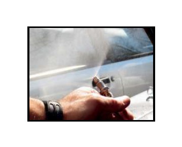
• Check the nozzle spray pattern while following this procedure and check for leaks.
***If pump goes on and fluid level doesn't go down, there is an obstruction in the tube or nozzle.***
***If the LED and/or pump fails to activate, check power and ground wiring for the LED and/or pump***
Step 2 Test Controller MAF/MAP Selection
The VC-MAF controller is designed to work with four different types of vehicle MAF/MAP sensors. A four position switch located inside the VCMAF (See picture on page 12 for location) allows the selection of the MAF/MAP sensor type. The VC-MAF reads the selection switch on power up to determine the mode of operation. The switch selection can be changed at any time, but power to the VC-MAF needs to be cycled before the new selection will be used.