FREE 1 to 3-Day Delivery on Orders $149+ Details
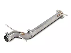
How to Install SLP Performance Pack - Level 1 (14-17 5.3L) on your Chevy Silverado
Installation Time
1 hours
Tools Required
- 1/4" Drive Socket Set
- T-15 Torx Bit
- Pliers
- Razor Blade
- Flat-head Screwdriver
- Trim Tool
PACKING LIST FOR 2014 GM TRUCK COLD AIR INTAKE
SECTION A – REMOVAL
The following section will guide you through the disassembly of the stock components. Special care should be taken to label fasteners and parts that are taken off during this procedure since many will be reused.
1. Cover both fenders with fender covers to protect the vehicle fi nish.
2. Disconnect the battery ground cable.
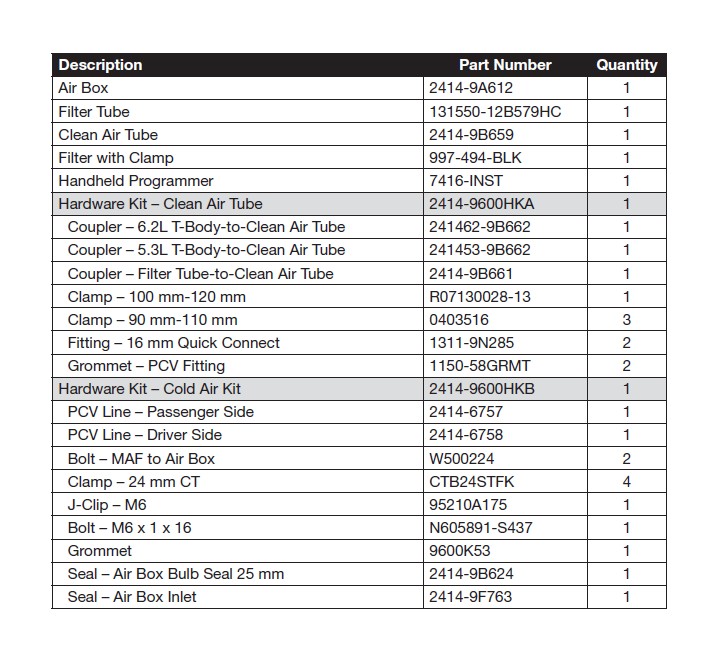
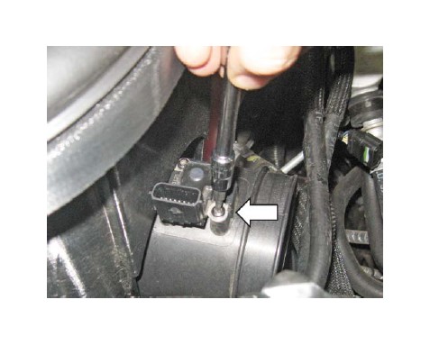
3. Disconnect the MAF sensor connector.
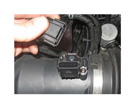
4. Using the T-15 Torx bits, remove the two (2) screws retaining the MAF sensor. Retain screws for installation.
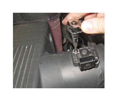
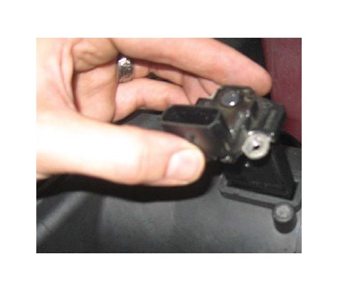
5. Remove the MAF sensor and retain for installation.
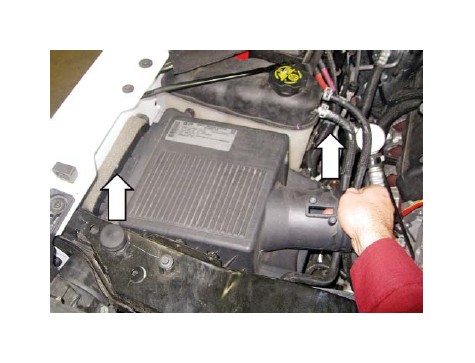
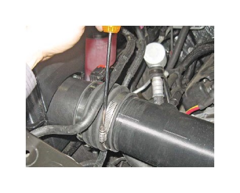
6. Loosen the clamps retaining the clean air tube to the air box and throttle body.
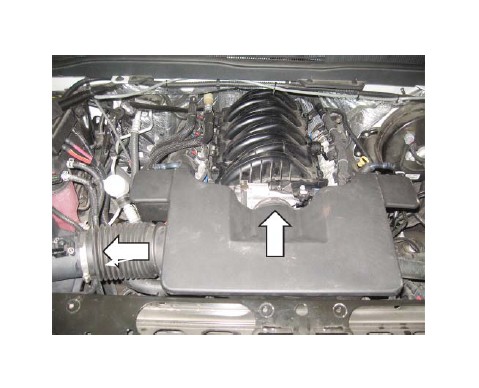
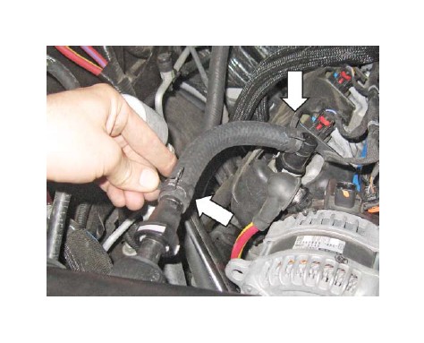
7. Disconnect the quick connect fi tting on the driver side of the clean air tube.
8. Disconnect the quick connect fi tting on the passenger side of the clean air tube.
9. Remove the clean air tube from the vehicle.
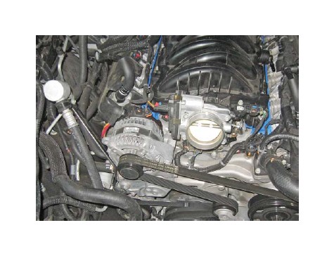
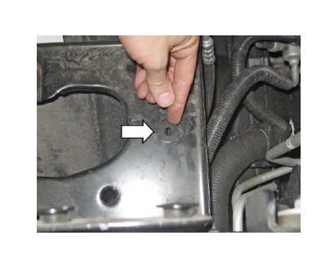
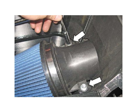
10. Remove the two (2) bolts holding the fender brace in place.
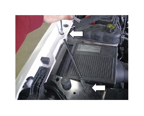
11. Remove the air box assembly from the vehicle, by pulling up. It is held in place by three (3) barb fi ttings.
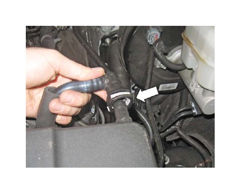
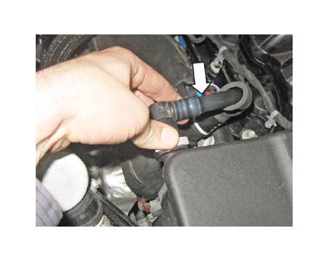
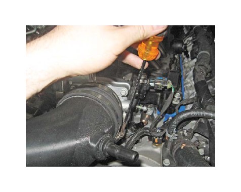
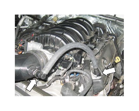
12. Disconnect and remove the PCV from the driver side valve cover. Retain for installation.
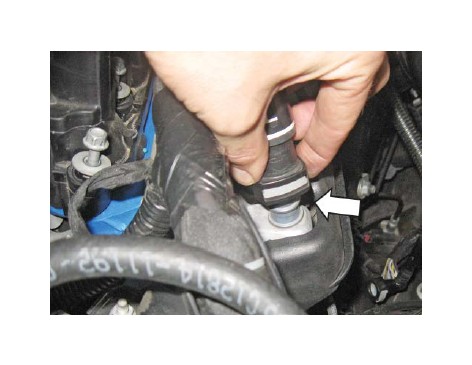
13. Disconnect and remove the PCV line from the passenger side valve cover.
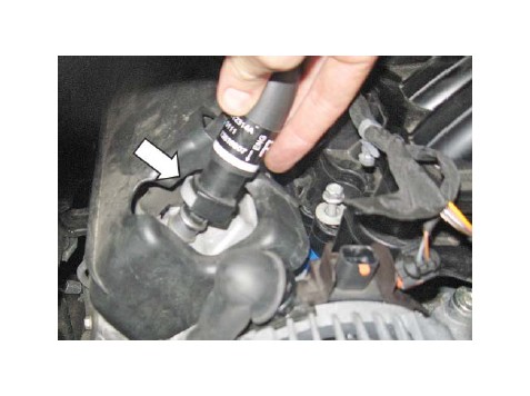
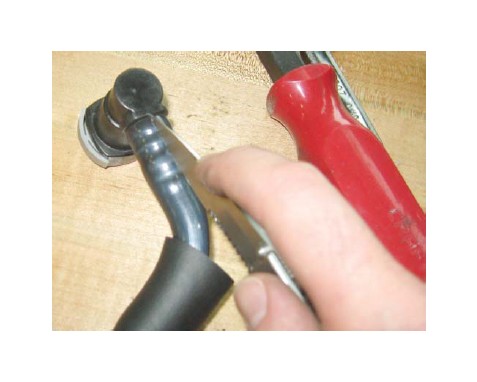
14. Using a razor, score the PCV lines just removed then pull out the quick connect fi ttings. Retain the fi ttings for installation.
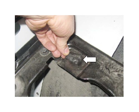
15. Remove the two (2) bolts holding the retaining support bracket between the radiator support and the fender.
SECTION B – INSTALLATION
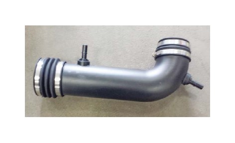
1. Install two (2) rubber grommets (P/N: 1150- 58GRMT) and fi ttings (P/N: 1311-9N285) into the clean air tube (P/N: 2414-9B659). Tip: Use glass cleaner or spray lubricant on the parts to help installation.
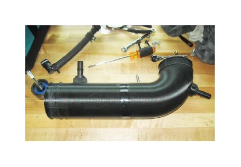
2. Install the fi lter tube-to-clean air tube coupler (PN: 2414-9B661) on the straight part of the tube and the throttle body-to-clean air tube coupler on the bent side. You will use either P/N: 241462- 9B662 or P/N: 241453-9B662 depending on the engine size. Tighten the inside hose clamps to 3 Nm and leave the outside loose.
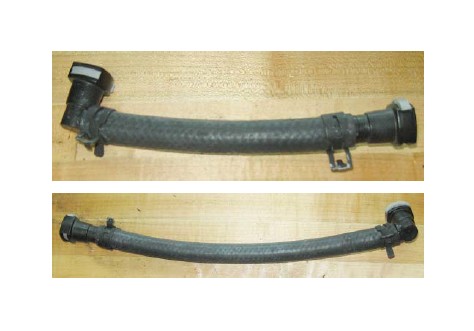
3. Insert one (1) straight quick connect and one 90-degree quick connect to each of the supplied PCV hoses (P/N: 2414-6757, 2414-6758). Use the supplied hose camps (P/N: CTB24STFK) to attach the fi ttings.
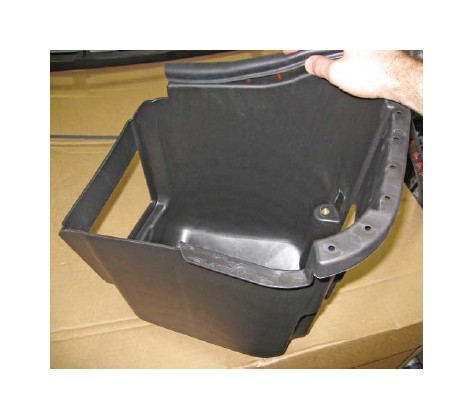
4. Install the J-clip (P/N: 95210A175) into the air box
tray as shown.
5. Install the grommet (P/N: 9600K53) into the air
box tray (P/N: 2414-9A612) as shown.
6. Place the bulb seal (P/N: 2414-9B624) onto the top of the air box and clip into the holes. Trim ends as required.
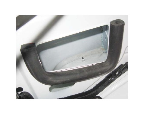
7. Clean off the fender well, then attach the inlet seal (P/N: 2414-9F673) as shown.
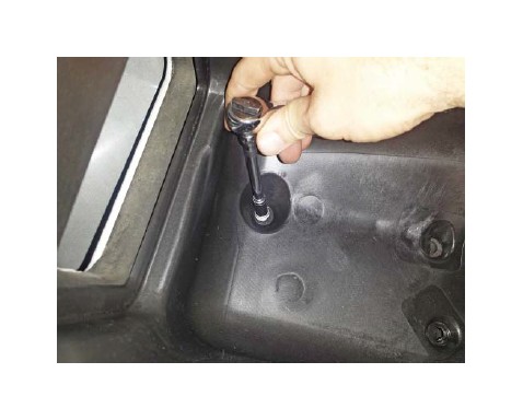
8. Insert the air box assembly into the vehicle, push down to seat the posts into the grommets.
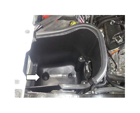
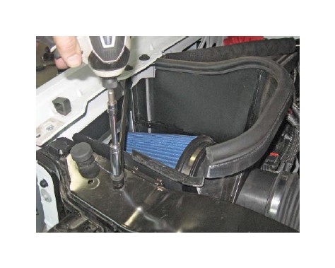
9. Thread and tighten the provided M6 bolt (P/N: N605891-S437) into the bottom of the air box. Tighten to 10 Nm.
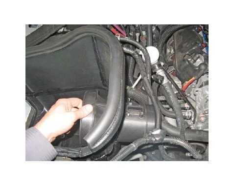
10. Insert the fi lter tube (P/N: 131550-12B579HC) into the air box tray.
11. Install the air fi lter (P/N: 997-494-BLK) onto the fi lter tube. Make sure the metal rib on the fi lter points down when the fi lter tube is oriented as shown. Tighten the fi lter clamp to 3 Nm.
12. Install the MAF sensor into the fi lter tube. Tighten the screws to 2 Nm.
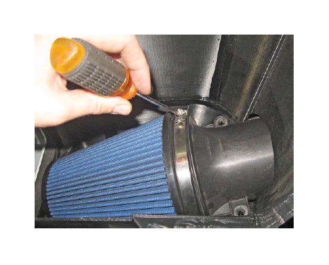
13. Using the two (2) M8 bolts (P/N: W500224), attach the fi lter tube to the air box. Tighten to 10 Nm.
14. Tighten the hose clamp attaching the clean air tube to the fi lter tube. Tighten to 3 Nm.
15. Tighten the clamp retaining the coupler to the throttle body. Tighten to 3 Nm.
16. Install the driver side PCV hose (P/N: 2414-6758) between the quick connect barbs on the valve cover and clean air tube assembly.
17. Install the passenger side PCV hose (P/N: 2414- 6757) between the quick connect barbs on the valve cover and clean air tube assembly.
18. Reinstall the support brace between the core support and fender.
19. The installation is now complete!
VEHICLE CALIBRATION INFORMATION
THIS KIT WAS SHIPPED WITH AN UNPROGRAMMED SCT HAND HELD PROGRAMMING DEVICE (7416-INST). THE DEVICE MAY NOT HAVE THE LATEST SOFTWARE INSTALLED. FAILURE TO UPDATE SCT DEVICE MAY RESULT IN ECM DAMAGE. PRIOR TO BEGINNING THE INSTALLATION OF THIS KIT, PLEASE PROCEED WITH THE FOLLOWING STEPS. THIS SHOULD BE DONE IN ADVANCE OF ANY VEHICLE DISASSEMBLY TO AVOID DELAYS DURING YOUR INSTALLATION. CALIBRATION SUPPORT IS PROVIDED MONDAY-FRIDAY 8 AM TO 5 PM EST.
UPDATING SCT DEVICE
1. Make sure you have the SCT updater software installed on your Windows PC. If you do not have it, follow this link: www.sctfl ash.com/software/ SCTDeviceUpdater.exe.
2. After downloading and installing the update software, open the program. There should be an icon on the desktop.
3. Once updater is open on the desktop, plug in the device.
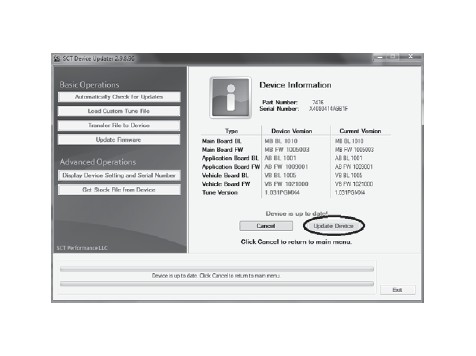
4. With the device plugged in, select “Automatically Check for Updates” from the Basic Operations menu.
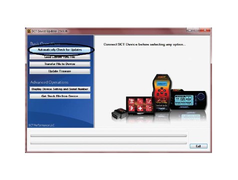
5. The device should start to update. Notice the bottom bar, it will let you know what part of the update it’s on. This can take some time, so be patient. The Internet connection and computer speed can impact updating times. Average time is 5-10 minutes.
6. The SCT Device Updater window displays “Device is up to date” when the update is done.
OBTAINING YOUR FACTORY CALIBRATION
1. Plug the SCT programmer (7416-INST) into the OBD port of the vehicle to which the supercharger kit will be installed.
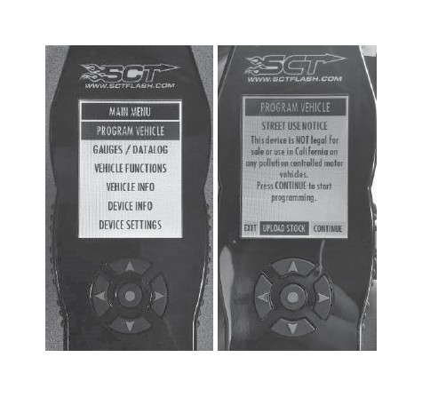
2. Select “Program Vehicle” from the Menu screen. Select “Upload Stock” to accept the terms of usage.
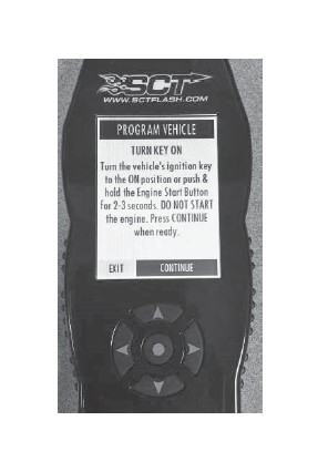
3. When prompted, turn the ignition to the KEY ON position and press “Continue”. DO NOT START THE ENGINE.
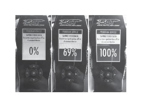
4. Wait for the programmer to fi nish saving stock data.
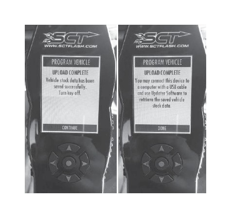
5. Turn the ignition to the KEY OFF position, press “Continue” and wait for the vehicle to power down.

6. The upload is complete. Press “Continue” and then “Done”.
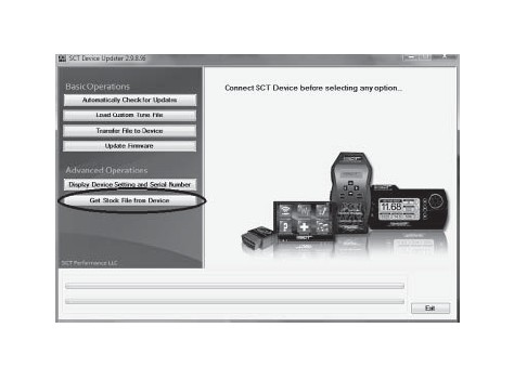
7. Disconnect the programmer from the vehicle. Reconnect it to the Windows PC and open the same update software used in step 2 of “Updating SCT Device”.
8. Select “Get Stock File from Device” from the Basic Operations menu.
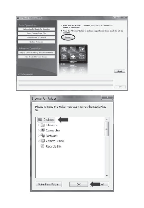
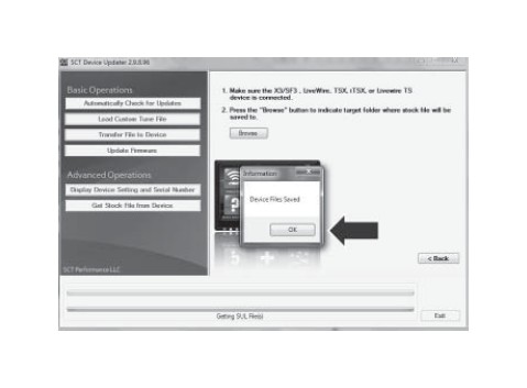
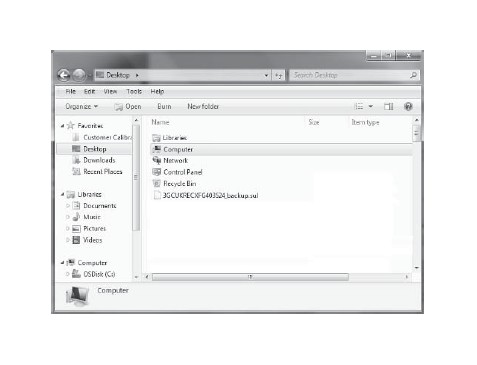
9. Select “Browse” and save the stock fi le to the desktop.
10. Add the text “backup” to the fi le name that contains the VIN number and e-mail a copy of the fi le to “[email protected]”. In the e-mail subject line, write: Calibration Request for Kit # XXXXXX (Enter Kit P/N).
11. SLP will reply to your e-mail within one (1) business day (Monday to Friday, 8 AM to 5 PM EST) with the calibration fi le for the vehicle.
12. FAILURE TO FOLLOW THE ABOVE STEPS MAY DELAY THE INSTALLATION OF THIS KIT. SLP NEEDS THIS DATA IN ORDER TO PROVIDE THE LATEST CALIBRATION FILES AVAILABLE FOR THE VEHICLE. IF YOU HAVE A NEW MODEL YEAR VEHICLE THAT IS NOT YET AVAILABLE IN OUR DATABASE, THE TURN AROUND TIME FOR THE CALIBRATION MAY EXCEED ONE (1) BUSINESS DAY. IF THE CALIBRATION IS NOT YET SUPPORTED, SLP WILL NOTIFY YOU OF THIS DELAY AS TO NOT CAUSE YOUR VEHICLE FROM BEING IMMOBILIZED DURING THIS TIME.
13. Save a copy of the fi le attached to the e-mail sent back from SLP to the PC desktop. This is the new calibration file.
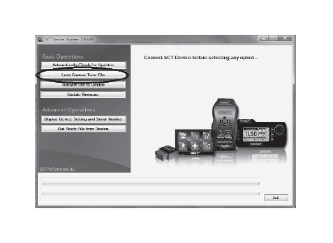
14. Plug the SCT device into the PC.
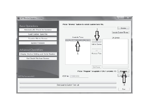
15. Open the SCT updater software and select “Load Custom Tune File”.
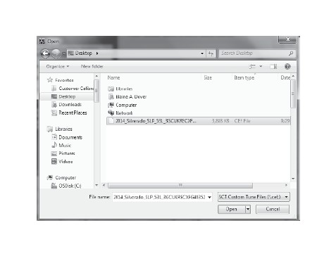
16. Select “Locate Custom Tune”.
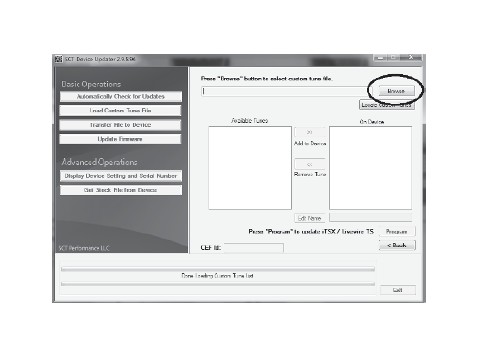
17. Locate and open the fi le that was attached in the e-mail sent back from SLP on the PC.
18. Select the tune from the left column (#1). Select the right arrows (#2). Select “Program” (#3).
19. The device is ready to reprogram the vehicle.
PROGRAMMING THE VEHICLE
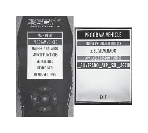
1. Plug the SCT programmer (7416-INST) into the OBD port of the vehicle that is to be calibrated.
2. Select “Program Vehicle” from the Main Menu screen. Select the SLP custom tune.
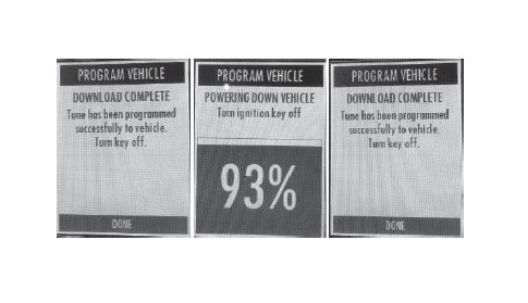
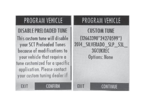
3. Select “Confi rm”, then Select “Continue”.
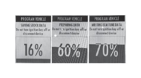
4. Wait for the programmer to fi nish the fl ashing process.
5. When prompted, turn the ignition key to the OFF position and unplug the SCT programmer from the OBD port.
6. Select “Done”. Programming is complete.