 FREE 1 to 3-Day Delivery on Orders $149+ Details
How to Install SkyJacker 6 in. Suspension Lift Kit on your F-150
Installation Time
1 days
Tools Required
- Safety Glasses
- Metric / Standard Wrenches & Sockets
- Hammer / Punch
- Floor Jack / Jack Stands
- Drill / Assorted Drill Bits
- Measuring Tape
- Torque Wrench
- Strut Spring Compressor (6" Lift)
- Reciprocating Saw / Cut Off Wheel

Shop Parts in this Guide
Before beginning the installation, thoroughly & completely read these instructions & the enclosed driver’s WARNING NOTICE. Affix the WARNING decal in the passenger compartment in clear view of all occupants. Please refer to the Parts List to insure that all parts & hardware are received prior to the disassembly of the vehicle. If any parts are found to be missing, contact SKYJACKER® Customer Service at 318-388-0816 to obtain the needed items. If you have any questions or reservations about installing this lift kit, contact SKYJACKER® Technical Assistance at 318-388- 0816.
Make sure you park the vehicle on a level concrete or asphalt surface. Many times a vehicle is not level (side-to-side) from the factory & is usually not noticed until a lift kit has been installed, which makes the difference more visible. Using a measuring tape, measure the front & rear (both sides) from the ground up to the center of the fender opening above the axle. Record this information below for future reference.
Driver Side Front:______________ Passenger Side Front:______________
Driver Side Rear:______________ Passenger Side Rear:_______________
IMPORTANT NOTES:
• 6" Lifts Only: If this suspension lift is to be installed on a vehicle with the factory TRX4 package Part # D960TRX4 (5/8" Thick Aluminum Coil Spacers) must be ordered seperately.
• 17"-18" OEM wheels can not be reused in the installation of this suspension lift. 18" diameter or larger aftermarket wheels or 20" OEM wheels must be used in the installation of this suspension lift.
• If larger tires (10% more than the OEM diameter) are installed, speedometer recalibration will be necessary. Contact your local Ram dealer or an authorized dealer for details.
• After installation, a qualified alignment facility is required to align the vehicle to the OEM specifications.
Front Installation:
1. With the vehicle on flat level ground, set the emergency brake &
block the rear tires / wheels.
2. Place a floor jack under the lower control arm’s front cross member & raise the vehicle. Place jack stands under the frame rails, behind the front wheel wells & lower the frame of the vehicle onto the jack stands.
3. Remove the front tires / wheels.
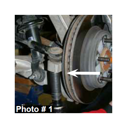
4. Remove the tie rod end from the OEM steering knuckle using a 22mm socket & tie rod remover or other suitable tool. (See Photo # 1)
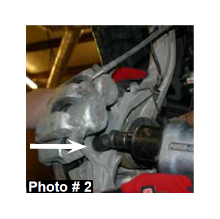
5. Remove the brake line bracket & brake caliper mounting bolts from the OEM steering knuckle using a 21mm socket. Remove the brake caliper assembly & simply wire the brake caliper assembly out of the way. It will not be necessary to disconnect the brake line from the brake caliper assembly. (See Photo # 2)
6. Remove the brake rotor.
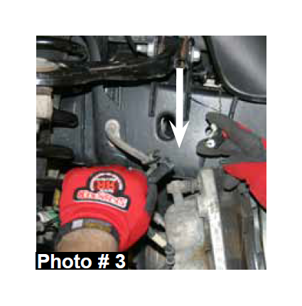
7. Disconnect the ABS sensor cable from the upper A-arm by opening
the retainer clip & disconnect the ABS sensor cable from behind the
inner fender liner. (See Photo # 3)
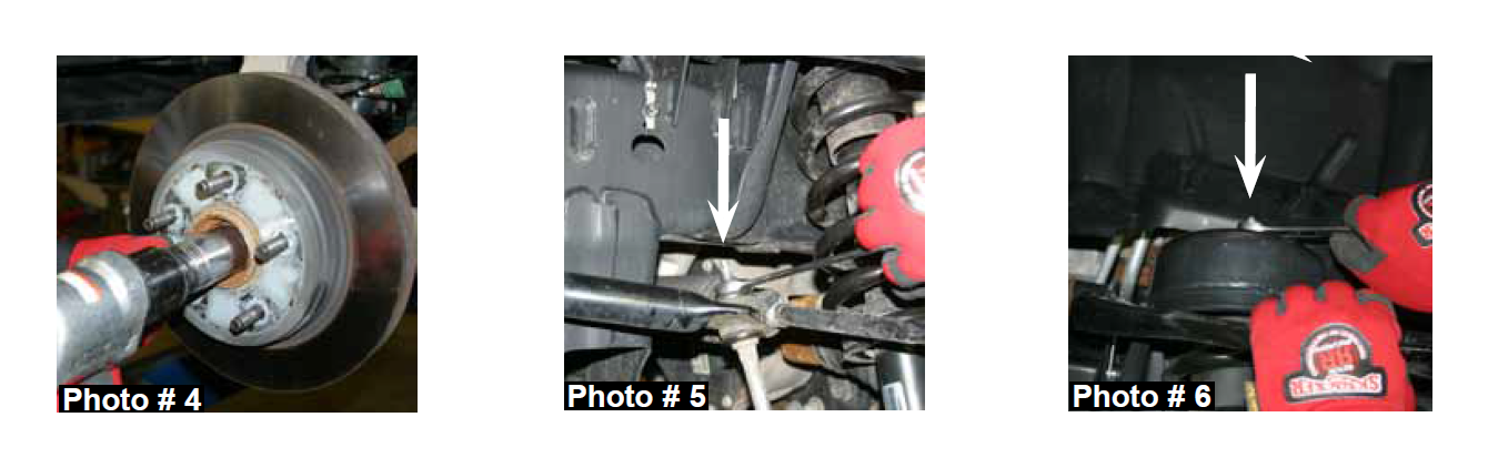
8. Remove the CV-shaft nut from the center of the hub assembly using a 1 7/16" socket. (See Photo # 4)
9. Remove the OEM sway bar end links using a 16mm & 18mm socket. (See Photo # 5)
10. Remove the three upper strut retaining nuts using a 15mm socket. (See Photo # 6)
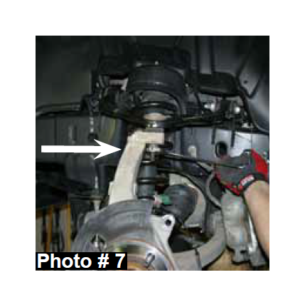
11. Remove the upper & lower ball joints from the OEM steering knuckle using a 21mm & 24mm socket & ball joint remover or other suitable tool. (See Photo # 7)
12. Remove the OEM steering knuckle. Once removed, remove the three hub bearing assembly bolts from the OEM steering knuckle using a 15mm socket.
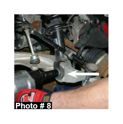
13. Remove the lower strut mount bolt from the lower A-arm using a 21mm & 24mm socket. Once removed, remove the OEM strut assembly. (See Photo # 8)
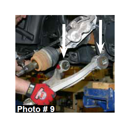
14. Remove the front & rear lower A-arm bolts using a 24mm socket & wrench. Once removed, remove the OEM lower A-arm. (See Photo # 9)
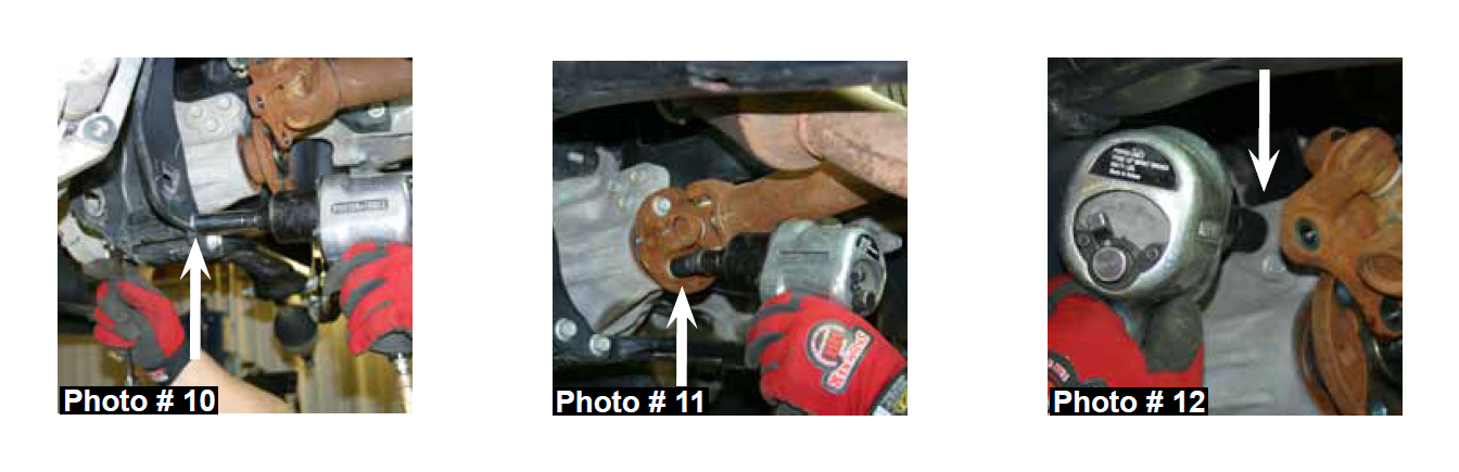
15. Remove the four rear cross member frame connecting bolts using a 18mm socket & remove the OEM rear cross member. (See Photo # 10)
16. Mark the position of the front differential flange & drive shaft flange. Note: These marks will be realigned during reassembly. Remove the four front drive shaft mounting bolts from the front differential using a 15mm socket. It will not be necessary to remove the drive shaft from the transfer case. Simply wire it out of the way. (See Photo # 11)
17. Disconnect the vaccum hose & electrical harness from the front differential. Support the front differential with a transmission jack & remove the differential mounting bolts using a 18mm socket. There are three rear upper, two driver side upper, & two on the passenger side front. Once these bolts are removed, lower the front differential out of the vehicle. (See Photo # 12)
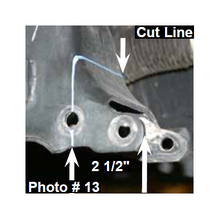
18. It will now be necessary to cut the OEM rear cross member bracket for differential clearance when the lift is installed. Locate the OEM driver side rear cross member bracket, measure from the edge of the OEM bracket over 2 1/2" & draw a line along the outer face of the bracket. (See Photo # 13) Connect the lines drawn on the front & rear sides of the bracket in order to have a single cutting reference line. Cut along the drawn line using a reciprocating saw or other similar tool.
19. Support the front differential with a transmission jack & install the front differential.
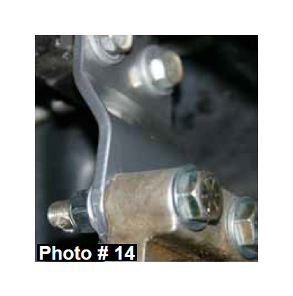
20. Install the passenger side differential drop bracket using the OEM hardware for the upper mounting holes & the supplied 1/2” x 2 1/4” fine thread bolts, washers, & nuts in the lower mounting holes. (See Photo # 14) Do not tighten at this time.
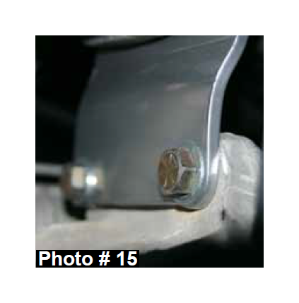
21. Install the driver side upper differential drop bracket using the OEM hardware in the upper mounting holes & the supplied 1/2” x 2” fine thread bolts, washers, & nuts in the lower mounting holes. (See Photo # 15) Do not tighten at this time.
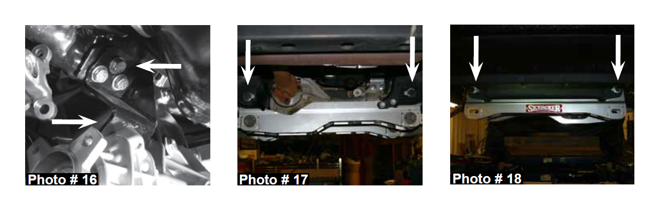
22. Install the driver side rear differential bracket using the supplied 12mm x 40mm hex head bolts, washers, & nuts in the upper mounting holes. Use the supplied 12mm x 30mm socket head bolts & washers in the lower mounting holes. (See Photo # 16) Tighten all differential bolts at this time.
23. Install the new Skyjacker rear cross member using the supplied 18mm x 140mm bolts, washers, & nuts in the upper holes & the OEM hardware in the lower passenger side holes of the new rear cross member using a 18mm & 1 1/6" socket & wrench. (See Photo # 17)
24. Install the new Skyjacker front cross member with the offset facing toward the front of the vehicle using the supplied 18mm x 140mm bolts, washers, & nuts in the upper holes of the front cross member using a 1 1/6" socket & wrench. (See Photo # 18)
25. Install the lower A-arms using the OEM hardware, 24mm socket, & wrench.
Note: If installing a 4" lift, proceed to Step # 29.
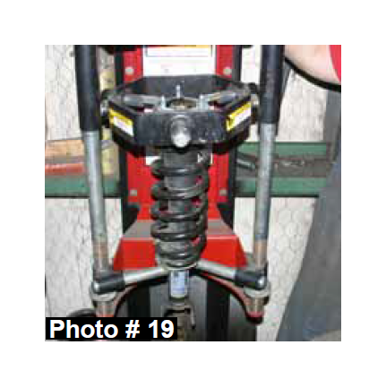
26. For upper strut mount alignment purposes, mark the location of the OEM upper strut mount & OEM coil spring prior to disassembly. Using a strut spring compressor, compress the coil spring of the OEM strut assembly. Remove the upper strut retaining nut & upper strut mount. (See Photo # 19)
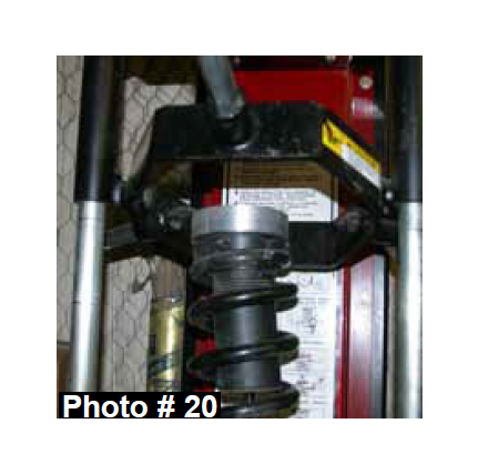
27. Install the new Skyjacker aluminum coil spring spacer on top of the OEM strut isolator pad. (See Photo # 20)
Note: If your vehicle is equipped with the TRX4 package, do not install the aluminum coil spring spacers (1 1/4" Thick) or severe driveline damage will occur. Instead, install the thinner aluminum coil spring spacers (5/8" Thick) included with Part # D960TRX4. ***(Must be ordered seperately)***
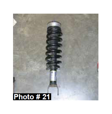
28. Install the OEM upper strut mount, aligning the marks made in Step # 26. Tighten the OEM retaining nut & uncompress the OEM coil spring. (See Photo # 21)
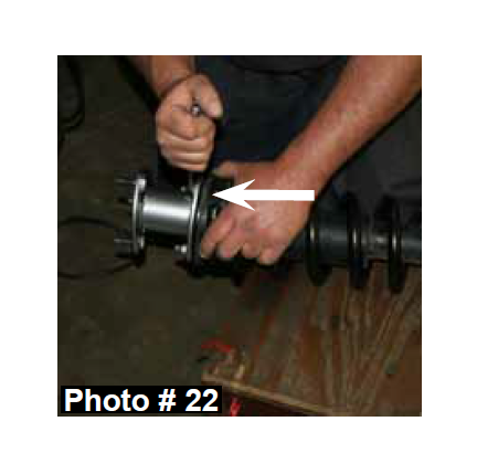
29. Install the new Skyjacker strut spacer on the top of each OEM strut assembly using the OEM hardware. (See Photo # 22)
30. Install the OEM hub bearing assembly to the new Skyjacker steering knuckle using the OEM hardware. Apply thread lock to the threads of each bolt & tighten using a 15mm socket.
31. Install the new Skyjacker steering knuckle to the lower A-arm ball joint.
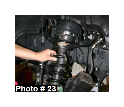
32. Install the strut assembly by aligning the three upper strut mount studs with the OEM mounting locations using the supplied 10mm nuts & a 15mm socket. (See Photo # 23)
33. Install the lower strut mount to the lower A-arm using the OEM hardware, 21mm, & 24mm socket.
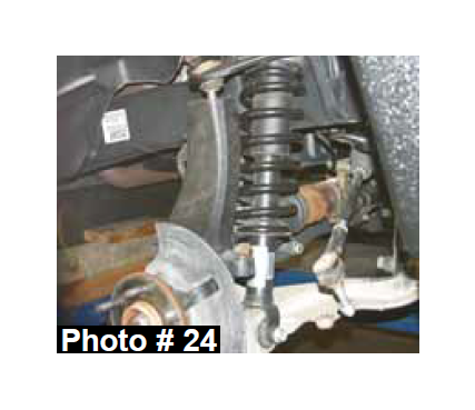
34. Install the CV-shaft using a 1 7/16" socket & install the upper ball joint to the new Skyjacker steering knuckle. (See Photo # 24) Note: It may be necessary to use a jack to raise the lower A-arm in order to install the upper ball joint.
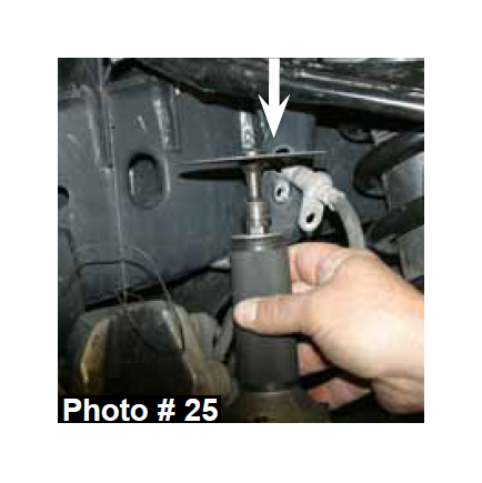
35. Remove the brake line mounting bolt from the frame. Using a cut off wheel or other similar tool, cut a notch in order to remove the brake line from the OEM brake line bracket. (See Photo # 25) Note: Be very careful note to cut or damage the OEM brake line.
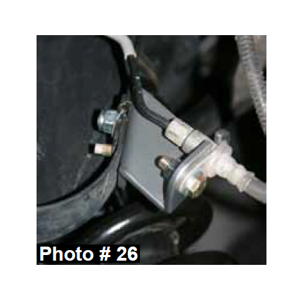
36. Install the new Skyjacker brake line relocation bracket & OEM brake line, using the OEM hardware, supplied 3/8" x 1" fine thread bolt, 5/16" x 1" fine thread bolt, washers, & nuts. (See Photo # 26)
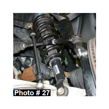
37. Install the tie rod end to the new Skyjacker steering knuckle using the OEM hardware. (See Photo # 27)
38. Install the new Skyjacker sway bar end links with the rubber bushings to the sway bar & the ball joint end to the lower A-arm using the supplied metal end link reducer bushings. (See Photo # 27)
39. Reconnect the ABS sensor cable to the upper A-arm & to the inner fender liner.
40. Install the brake rotor, brake line bracket, & brake caliper assembly using the OEM hardware.
41. Install the new Skyjacker front drive shaft spacer between the differential flange & drive shaft using the supplied 12mm x 50mm bolts & 19mm wrench. Note: Apply thread lock to the threads of these bolts & be sure to align the previously made marks on the front differential flange & drive shaft flange.
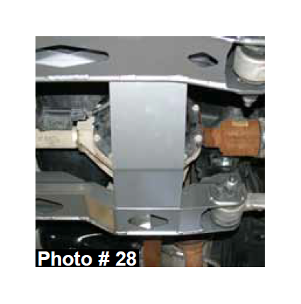
42. Hold the new Skyjacker front differential skid plate in place aligning the mounting locations of the skid plate to the front & rear cross members. Install the new Skyjacker front differential skid plate using the supplied 5/16" x 1" fine thread bolts, washers, nuts, 1/2" wrench, & 1/2" socket. (See Photo # 28)
43. Install the front tires / wheels & lower the front of the vehicle to the ground.
Rear Installation:
1. With the vehicle on flat level ground, block the front tires / wheels.
2. Place a floor jack under the vehicle & raise the vehicle. Place the jack stands under the frame rails & lower the frame of the vehicle onto the jack stands.
3. Remove the rear tires / wheels.
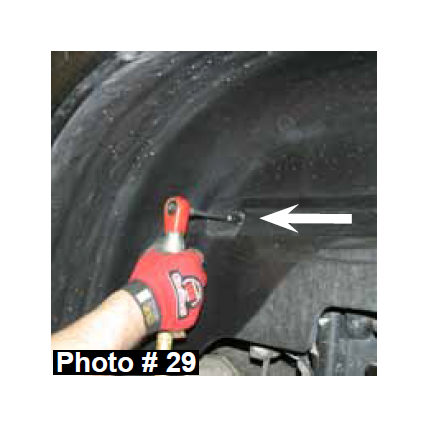
4. Remove the driver side inner fender liner using a 8mm socket. (See Photo # 29)
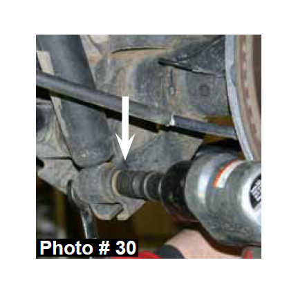
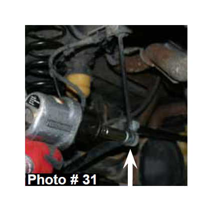
5. Remove the OEM rear shocks & rear sway bar end links. (See Photos # 30 & # 31)
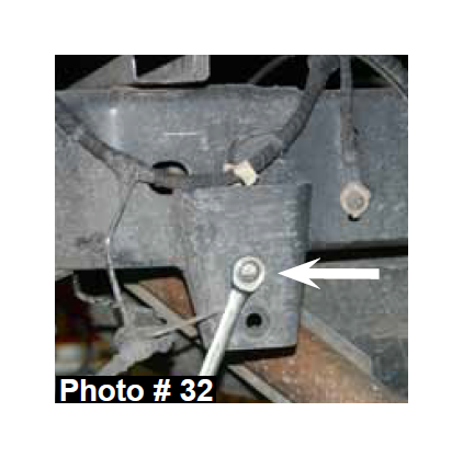
6. Disconnect the ABS wire retaining clip & brake line support bracket from the frame. (See Photo # 32)
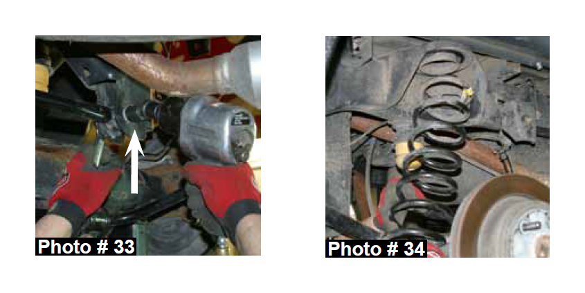
7. Disconnect the OEM track bar from the frame mount using a 21mm socket & wrench. (See Photo # 33)
8. While checking for appropriate slack in ABS lines, brake lines, differential breather hose, & etc. Lower the rear axle & remove the OEM coil springs. (See Photo # 34)
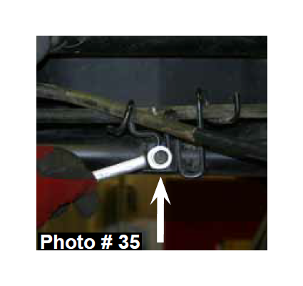
9. Remove the E-brake cable support bracket from the driver side lower control arm using a 13mm socket. (See Photo # 35)
10. Disconnect the OEM upper & lower control arms from the frame rail using a 24mm socket. Note: Only remove one side at a time so that the axle does not move.
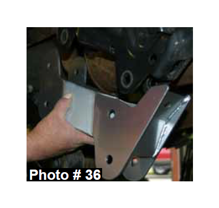
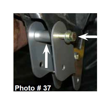
11. Install the new Skyjacker control arm relocation bracket over the OEM bracket so the new bracket faces the outside of the vehicle. Install using the supplied crush sleeves, 5/8" x 4 1/2" fine thread bolts, 9/16" x 1 1/2" fine thread bolt, washers, & nuts. Attach the OEM upper & lower control arms to the new control arm relocation bracket using the OEM hardware. (See Photos # 36 & # 37)
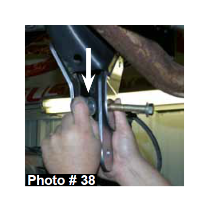
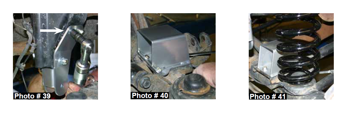
12. Install the new Skyjacker track bar relocation bracket by putting the rear flange of the new track bar relocation bracket to the inside of the OEM track bar bracket & the front flange of the new track bar relocation bracket to the outside of the OEM track bar bracket. Align the new track bar relocation bracket & drill template (Part # D960RTBTEM) with the OEM mounting location & install the supplied crush sleeve, 9/16" x 3 /12" fine thread bolt, washers, & nut. Once the 9/16" bolt & nut are tightened, use the drill template as a guide & a 7/16" drill bit to drill the upper rear mounting location. Once drilled, install the supplied 7/16" x 1 1/2" fine thread bolt, washers, & nut. Using a 7/16" drill bit, drill the two front mounting locations & install the supplied 7/16" x 1 1/2" fine thread bolts, washers, & nuts. (See Photos # 38 & # 39)
13. Align the new Skyjacker bump stop spacer mounting locations with the locations of the OEM bump stop pad & install using the supplied 3/8" x 1 fine thread bolts, 7/16" x 1 1/4" fine thread bolt, washers, & nuts. (See Photo # 40)
14. Install the new Skyjacker rear coil springs. (See Photo # 41)
15. Attach the OEM track bar to the new Skyjacker track bar relocation bracket using the OEM hardware & 21mm socket & wrench.
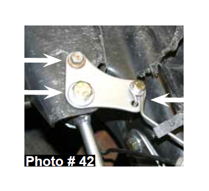
16. Insert the 5/8” polyurethane hourglass bushings into each end of the new Skyjacker sway bar end links. Insert the supplied 1/2" x 1 1/2” metal sleeve into each bushing. Using a 1/2" drill bit, enlarge the upper rear sway bar end link mounting location. Attach the new sway bar end link, new brake line relocation bracket, & OEM brake line support bracket using the OEM 8mm bolt, supplied 1/2" x 2 1/2” fine thread bolts, 5/16" x 1 fine thread bolt, washers, & nuts. (See Photo # 42)
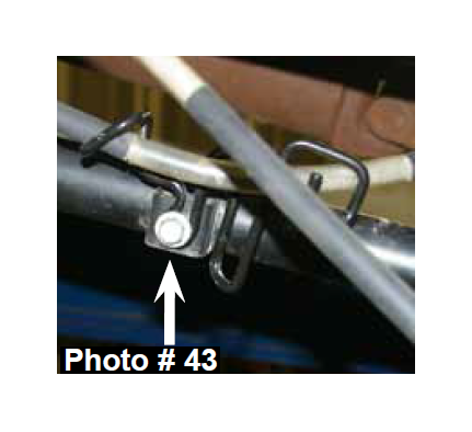
17. Bend the front wire of the OEM E-brake cable support bracket forward & place the passenger side E-brake cable thru the E-brake cable support bracket, while leaving the driver side E-brake cable loose. Install the E-brake cable support bracket to the driver side lower control arm using the OEM hardware & a 13mm socket. (See Photo # 43)
18. Install the new Skyjacker rear shocks & inner fender liner using the OEM hardware.
19. Install the rear tires / wheels & lower the vehicle to the ground.
FINAL NOTES:
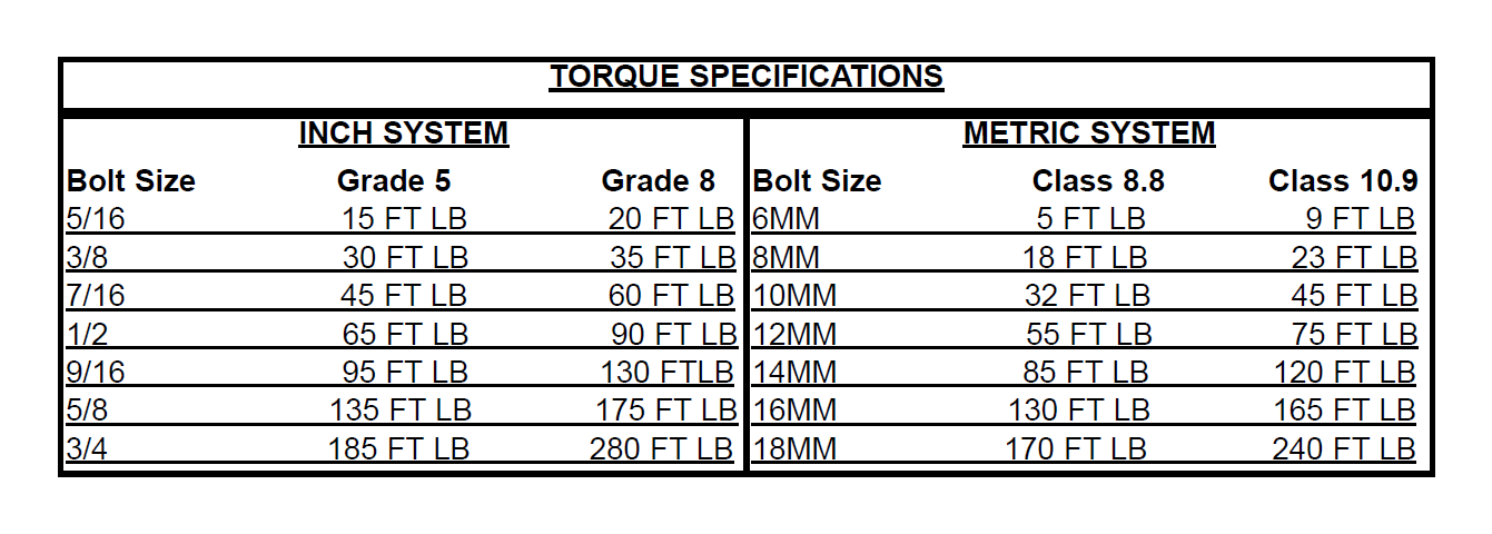
• After the installation is complete, double check that all nuts & bolts are tight. Refer to the following chart for the proper torque specifications. (Do not retighten the nuts & bolts where thread lock compound was used.)
• With the vehicle placed on the ground, cycle the steering lock to lock & inspect the steering, suspension, brake lines, front & rear drivelines, fuel lines, & wiring harnesses for proper operation, tightness, & adequate clearance.
• Have the headlights readjusted to the proper settings.
• Have a qualified alignment center realign the front end to the OEM specifications.
• After the first 100 miles, check all hardware for the proper torque & periodically thereafter.
• The above specifications are not to be used when the bolt is being installed with a bushing.

