 FREE 1 to 3-Day Delivery on Orders $149+ Details
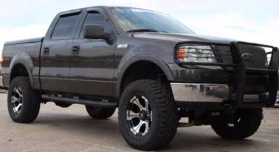
How to Install SkyJacker 6 in. Lift System on your F-150
Installation Time
1 days
Tools Required
- Safety Glasses
- Metric / Standard Sockets & Wrenches
- Spring Compressor
- Floor Jack
- Jack Stands
- Measuring Tape
- Torque Wrench
- Transmission Jack
- Grinder / Cut Off Wheel

Shop Parts in this Guide
Installation Instructions
Before beginning the installation, thoroughly & completely read these instructions & the enclosed driver’s WARNING NOTICE. Affix the WARNING decal in the passenger compartment in clear view of all occupants. Please refer to the Parts List to insure that all parts & hardware are received prior to the disassembly of the vehicle. If any parts are found to be missing, contact SKYJACKER®
Customer Service at 318-388-0816 to obtain the needed items. If you have any questions or reservations about installing this lift kit, contact SKYJACKER® Technical Assistance at 318-388- 0816.
Make sure you park the vehicle on a level concrete or asphalt surface. Many times a vehicle is not level (side-to-side) from the factory & is usually not noticed until a lift kit has been installed, which makes the difference more visible. Using a measuring tape, measure the front & rear (both sides) from the ground up to the center of the fender opening above the axle. Record this information below for future reference.
Driver Side Front: ____________ Passenger Side Front:_______________
Driver Side Rear: ____________ Passenger Side Rear:_______________
IMPORTANT NOTES:
• This lift is determined from the amount of lift to the front of the vehicle, while only lifting the rear to a position level with the front.
• If larger tires (10% more than the stock diameter) are installed, speedometer recalibration will be necessary. Contact your local Ford dealer or an authorized dealer for details.
• After installation a qualified alignment facility is required to align the vehicle to factory specifications.
Front Installation:
1. With the vehicle on flat level ground, set the emergency brake & block the rear tires.
2. Place a floor jack under the lower control arm’s front cross member & raise the vehicle. Place jack stands under the frame rails, behind the front wheel wells & lower the frame onto the stands.
3. Remove the front tires / wheels using a 22mm socket.
4. Remove the OEM skid plate located under the front differential.
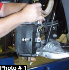
5. Remove the brake caliper using a 13mm wrench. (See Photo # 1)
Note: It will not be necessary to remove the brake line from the brake caliper. Simply wire it out of the way until reassembly. Remove the brake rotor.
6. Disconnect the cv-axle shaft from the differential & steering knuckle.
Note: Mark the driver & passenger side cv-axle shafts as they are removed.
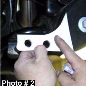
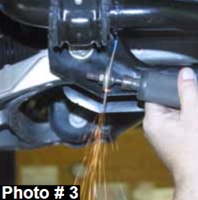
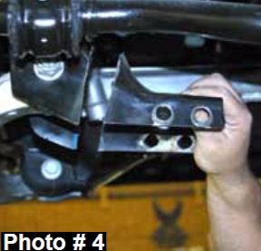
7. It will now be necessary to cut the rear cross member for differential clearance. Unbolt & remove the rear cross member from the frame. Locate the supplied template found on page # 13. Line the two holes off the template up with the rear mounting holes found on the driver side of the rear cross member. (See Photo # 2) Draw a straight line along the outer edge of the template. Place the template on the opposite side, reverse the template, & draw a line. Connect the two lines on the top & cut along the lines, using a grinder, cut off wheel, or similar tool. Note: Be sure to cut all the way around the cross member. (See Photo # 3) Remove this piece from the frame. (See Photo # 4)
8. With the cv-axle shafts removed, disconnect the ABS line & vaccum line from the hub bearing assembly.
9. Disconnect the outer tie rod from the steering knuckle using a 21mm socket & tie rod remover or other suitable tool.
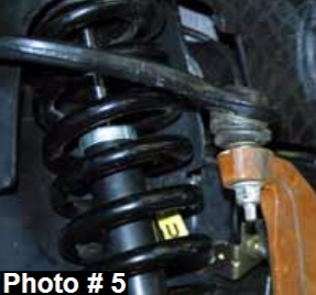
10. Disconnect the upper & lower ball joints from the OEM steering knuckle using a 21mm socket & ball joint remover or other suitable tool. (See Photo # 5) Remove the OEM steering knuckle.
11. Disconnect the front sway bar from the frame. Disconnect the sway bar links from the lower A-arm & remove the sway bar.
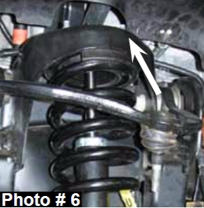
12. Remove the lower strut mount bolt from the lower A-arm using a 1 3/16” & 1 1/16” socket. Disconnect the three upper strut mount bolts from the frame using a 15mm wrench. (See Photo # 6)
13. Remove the lower A-arm mounting bolts from the frame & remove the lower A-arm.
14. Disconnect the front drive shaft from the differential. Note: It will not be necessary to remove the drive shaft from the transfer case. Simply wire it out of the way.
15. While supporting the front differential with a transmission jack, remove the differential mounting bolts. There are two on the drivers side & one on the passenger side. With the bolts removed, lower the differential out of the vehicle.
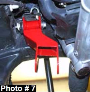
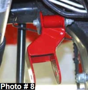
16. Locate the new Skyjacker driver & passenger side differential brackets. Note: The driver side bracket is the thinner of the two. Attach the driver side & passenger side brackets to the OEM mount using the OEM hardware. (See Photo # 7 & 8)
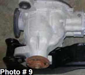
17. Locate the new Skyjacker rear cross member. Note: There is a differential mount made on to the driver side of this cross member. The differential must be attached to this mount before the cross member can be installed. Attach the differential at this point using a 12mm x 90mm bolt, washer, & nut. (See Photo # 9)
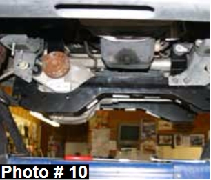
18. Using a transmission jack, install the new Skyjacker rear cross member & differential. Attach the rear cross member to the OEM rear A-arm mounts using the OEM hardware. Attach the differential to the new Skyjacker driver & passenger side brackets using the 12mm x 90mm bolts, washers, & nuts. (See Photo # 10)
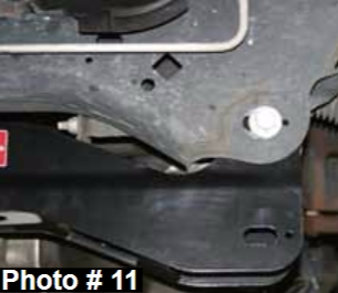
19. Attach the new Skyjacker front cross member to the OEM front A-arm mounts using the OEM hardware. (See Photo # 11)
20. Attach the front drive shaft to the differential using the OEM hardware.
21. Attach the lower A-arms to the new Skyjacker cross members using the 18mm x 150mm bolts, washers, & nuts.
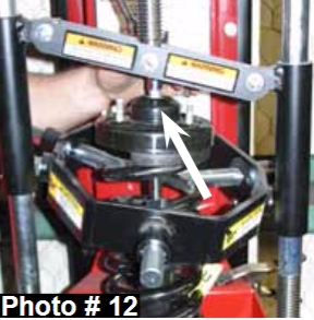
22. Using a strut spring compressor, unload the tension on the upper strut mount of the OEM coil assembly. Remove the upper shock retainingnut using 9/16” socket & slide the OEM strut out from the bottom of the OEM strut assembly. (See Arrow in Photo # 12)
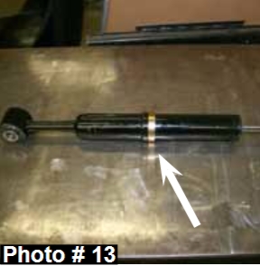
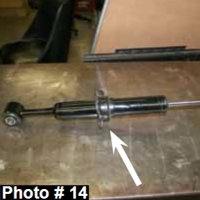
23. At the upper hex portion of the shaft, rotate the shaft of the new Skyjacker strut assembly counter clockwise in order to unlock & extend the shaft of the new Skyjacker strut assembly. Assemble thenew Skyjacker strut by installing the new Skyjacker coil seat spacer ring Part # F964ST-SP1, new Skyjacker coil spring seat, new Skyjacker coil spring pad, & OEM bump stop on the new Skyjacker strut. (See Photo # 13 & # 14) Once the coil spring seat spacer rings have been installed check all suspension components for any contact or interference. If suspension component contact or interference is present, lower the coil spring seat by removing a coil spring seat spacer ring until no contact or interference is present.
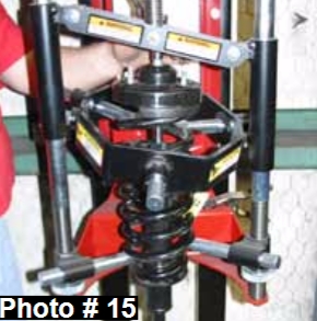
24. Assemble the new Skyjacker strut using the OEM coil spring & a strut spring compressor. (See Photo # 15)
25. Install the new Skyjacker strut assembly into the vehicle by attaching the OEM upper mount using the OEM hardware.
26. Attach the strut assembly to the lower A-arm using the OEM hardware. Note: "Ford Torque Specifications" for this bolt is 351 ft lbs.
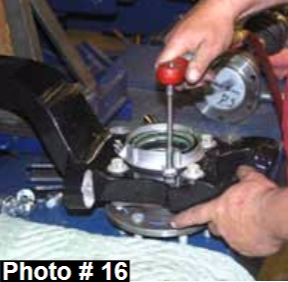
27. Remove the OEM hub assembly from the OEM steering knuckle & install onto the new Skyjacker steering knuckle. (See Photo # 16) Note: The OEM dust shield will not be reused. Install the hub assembly so that the ABS line is pointing toward the top of the steering knuckle.
28. Attach the new Skyjacker steering knuckle to the lower ball joint (Torque to 111 ft. lbs) & upper ball joint (Torque to 85 ft. lbs.) using the OEM hardware. Attach the outer tie rod using the OEM hardware. (Torque to 111 ft.lbs.) Note: Periodically re-torque the upper / lower ball joints & outer tie rod. Install the cv-axle shafts using the OEM hardware.
29. On the rearward side of the new Skyjacker steering knuckle, there is a new mounting location for the OEM ABS line. Using the 3/8” cable clamps & the 5mm x 12mm bolts, attach the ABS line to this new location.
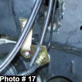
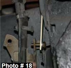
30. Locate the OEM brake line bracket on the frame rail. Remove the OEM bracket from the frame rail & install the new Skyjacker drop bracket at this position. Attach the new Skyjacker drop bracket to the frame rail using the OEM hardware. Attach the OEM brake line bracket to the new Skyjacker drop bracket using the 1/4" x 1” fine thread bolts, washers, & nuts. (See Photo # 17) Note: Some mounting configurations require the new Skyjacker drop bracket to be flattened. This can be accomplished by placing the new Skyjacker drop bracket in a vise or tapping flat with a hammer. Some mounting configurations will also require the upper hole of the new Skyjacker drop bracket to be enlarged by drilling using a 13/32" drill bit. (See Photo # 18)
31. Attach the brake rotor & brake caliper to the new Skyjacker steering knuckle using the OEM hardware.
32. Install the new Skyjacker sway bar drop brackets. Attach to the OEM mount on the frame using the OEM hardware. Attach the sway bar to the new Skyjacker brackets using the 7/16" x 1 1/2” fine thread bolts, washers, & nuts. Note: The brackets will install with the open portion towards the inside of the vehicle & the pointed end towards the rear of the vehicle. Attach the sway bar links to the lower A-arms using the OEM hardware.
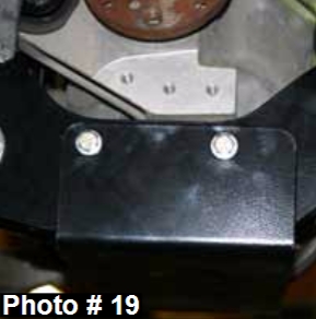
33. Hold the new Skyjacker front differential skid plate in place with the mounting holes of the skid plate facing the rear of the front & rear cross members. Using the four 5/16" x 1" bolts, eight 5/16" washers, four 5/16" nuts, 1/2" wrench, & 1/2" socket, install the front differential skid plate. (See Photo # 19)
34. Install the front tires / wheels & lower the front of the vehicle to the ground.
Rear Installation:
1. With the vehicle on flat level ground, set the emergency brake & block the front tires.
2. Raise the rear of the vehicle & support the frame rails using jack stands.
3. Remove the rear tires / wheels using a 22mm socket.
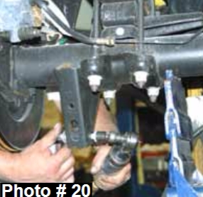
4. Remove the OEM rear shocks using a 15mm & 18mm socket. (See Photo # 20)
5. Remove the OEM rear U-bolts using a 21mm socket.
6. Disconnect the OEM rear brake line bracket from the frame rail.
Note: If installing rear add-a-leafs, skip to step # 9 of the rear installation. Rear Spring Installation: Part # FR45S
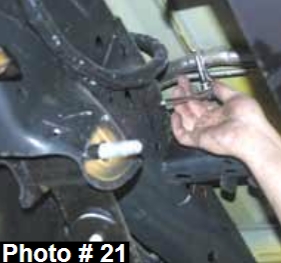
7. To allow for the axle to lower down far enough to install the new Skyjacker rear leaf springs, the fuel filler extension must be disconnected from the bed. Note: These bolts are located behind the fuel door. The fuel extension clamp located on the outside of the driver side frame rail must also be disconnected. (See Photo # 21)
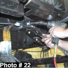
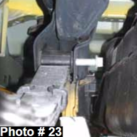
8. Lower the axle down so that there is no load on the rear leaf springs. Remove the rear leaf spring eye bolts using a 21mm socket. (See Photo # 22) Note: It will be necessary to loosen the gas tank straps to allow the gas tank to slide over enough to get the leaf spring eye bolts out. (See Photo # 23) Be sure to support the gas tank with a transmission jack. On the passenger side, it will be necessary to disconnect & remove the exhaust. Note: Disconnect from in front of the OEM muffler & remove. Remove the OEM rear leaf spring.
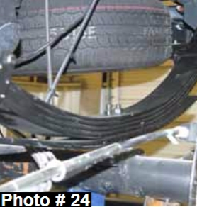
9. Install the new Skyjacker rear spring on top of the OEM block. (See Photo # 24) Note: Be sure to install the rear leaf spring with the long end of the spring towards the rear. There is a degree shim attached to the bottom of the new Skyjacker rear leaf spring to correct pinion angle. Be sure that the thick portion of the shim is pointed towards the rear of the vehicle & the tie bolt heads seat securely into the OEM block.
10. Install the new Skyjacker rear U-bolts (Torque to 130 ft. lbs.) & skip to Step # 16 of the rear installation.
Note: Do not tighten the leaf spring eye bolts until the vehicle is on the ground with the weight of the vehicle on the springs.
Rear Add-A-Leaf Installation: Part # R3440
11. Lower the axle down to gain access to the rear leaf spring. Note: To perform the installation of add-a-leafs properly, you must use two large C-clamps to contain the elastic potential energy in a leaf spring when the center tie bolts are being removed.
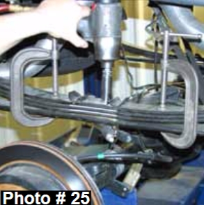
12. Attach & tighten a C-clamp on each end of the rear leaf spring to hold the rear leaf spring assembly securely together. (See Photo #25) Using locking-pliers to hold the head of the two center bolts, loosen & remove them. With care, slowly loosen & remove the C-clamps.
13. Insert the new Skyjacker tie bolts through the new Skyjacker axle wedge shim (thick end towards the rear bumper), OEM bottom overload leaf, new Skyjacker add-a-leaf, & through the OEM rear leaf spring pack. Note: Only finger tighten the nut at this time.
NOTE: DO NOT USE THE CENTER TIE BOLTS TO DRAW THE REAR LEAF SPRING LEAVES TOGETHER. FAILURE OF ANY COMPONENT CAN CAUSE AN EXPLOSIVE DISASSEMBLY & POSSIBLE INJURY!
14. Place one C-clamp on each side of the center bolts & tighten evenly. Once the C-clamps have drawn the leaves securely together, hold the center tie bolt heads with locking-pliers & tighten the nuts. (Torque to 41 ft. lbs.) Remove the C-clamps & cut off the excess length of the tie bolts.
15. Install the new Skyjacker U-bolts. (Torque to 130 ft. lbs.)
16. Install the rear tires / wheels & lower the vehicle to the ground.
17. Attach the new Skyjacker rear brakeline relocation bracket to the OEM mount on the frame rail using the OEM hardware. Attach the OEM bracket to the new Skyjacker relocation bracket using the 1/4" x 1” fine thread bolt, washers, & nut.
18. Install the new Skyjacker rear shocks.
FINAL NOTES:
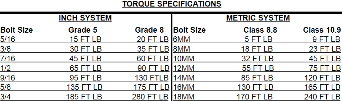
• After the installation is complete, double check that all nuts & bolts are tight. Refer to the following chart again for the proper torque specifications. (Do not retighten the nuts & bolts where thread lock compound was used.)
• With the vehicle placed on the ground, cycle the steering lock to lock & inspect the steering, suspension, brake lines, front & rear drivelines, fuel lines, & wiring harnesses for proper operation, tightness, & adequate clearance.
• Have the headlights readjusted to the proper settings.
• Have a qualified alignment center realign the front end to the factory specifications.
• Retorque all the bolts after the first 100 miles.

