 FREE 1 to 3-Day Delivery on Orders $149+ Details
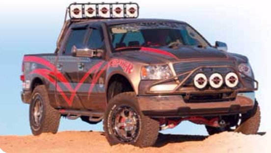
How to Install SkyJacker 6 in. Lift System on your F-150
Installation Time
1 days
Tools Required
- Safety Glasses
- Metric / Standard Wrenches & Sockets
- Spring Compressor
- Floor Jack
- Jack Stands
- Measuring Tape
- Torque Wrench
- Transmission Jack
- 10,000 lb Shop Press
Installation Instructions
Before beginning the installation, thoroughly & completely read these instructions & the enclosed driver’s WARNING NOTICE. Affix the WARNING decal in the passenger compartment in clear view of all occupants. Please refer to the Parts List to insure that all parts & hardware are received prior to the disassembly of the vehicle. If any parts are found to be missing, contact SKYJACKER® Customer Service at 318-388-0816 to obtain the needed items. If you have any questions or reservations about installing this product, contact SKYJACKER® Technical Assistance at 318-388- 0816.
Make sure you park the vehicle on a level concrete or asphalt surface. Many times a vehicle is not level (side-to-side) from the factory & is usually not noticed until a lift kit has been installed, which makes the difference more visible. Using a measuring tape, measure the front & rear (both sides) from the ground up to the center of the fender opening above the axle. Record this information below for future reference.
Driver Side Front: ________________ Passenger Side Front:_______________
Driver Side Rear: ________________ Passenger Side Rear:_______________
IMPORTANT NOTES:
• This lift is determined from the amount of lift to the front of the vehicle, while only lifting the rear to a position level with the front.
• If larger tires (10% more than the stock diameter) are installed, speedometer recalibration will be necessary. Contact your local Ford dealer or an authorized dealer for details.
• After installation a qualified alignment facility is required to align the vehicle to factory specifications.
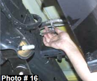
Front Installation:
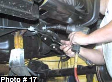
1.With the vehicle on flat level ground, set the emergency brake &
block the rear tires. Place a floor jack under the lower control arm’s
front cross member & raise the vehicle. Place jack stands under the
frame rails, behind the front wheel wells & lower the frame onto the
jack stands.
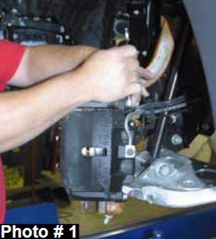
2. Remove the front tires / wheels using a 22mm socket. Remove the
brake caliper using a 13mm wrench. (See Photo # 1) It will not be
necessary to remove the brake line from the brake caliper. Simply
wire it out of the way until reassembly. Remove the brake rotor.
3. Disconnect the ABS line from the steering knuckle. Disconnect the
outer tie rod from the steering knuckle using a 21mm socket. It may
be necessary to strike the side of the knuckle to dislodge the tie rod
end. Be careful not to damage the tie rod itself.
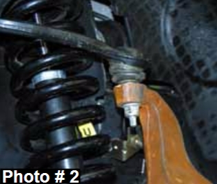
4. Disconnect the upper & lower A-arm ball joint from the OEM steering
knuckle using a 21mm socket. (See Photo # 2) Remove the steering
knuckle.
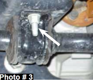
5. Disconnect the front sway bar from the frame. (See Photo # 3)
Disconnect the sway bar links from the lower A-arm & remove.
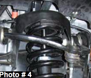
6. Remove the lower strut mount bolt from the lower A-arm using a
1 3/16” & 1 1/16” socket. Disconnect the three upper strut mount bolts from
the frame using a 15mm wrench. (See Photo # 4)
7. Remove the lower A-arm mounting bolts from the frame & remove the lower A-arm.
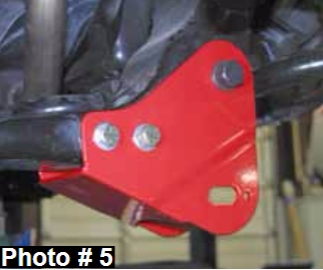
8. Locate the new Skyjacker rear cross member brackets. They will
attach to the OEM cross member location using the 1/2" x 5 1/2"
fine thread bolts, washers, & nuts. The bracket will attach to the
OEM A-arm position using the 18mm x 150mm bolts, washers, &
nuts. (See Photo # 5) Be sure to use the crush sleeves Part #
CS3980 along with the 18mm bolts between the OEM A-arm
mount.
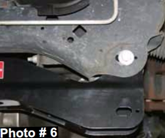
9. Install the new Skyjacker front cross member using the 18mm x
150mm bolts, washers, & nuts. (See Photo # 6)
10. Attach the lower A-arms to the new Skyjacker cross members
using the OEM hardware. Note: Skyjacker's design allows for the
use of after market alignment kits. Available from an authorized
Skyjacker dealer, order two of Part # F462-AK.
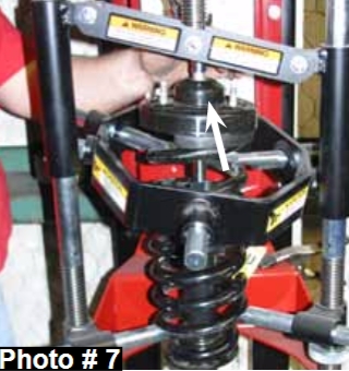
11. Using a strut spring compressor, unload the tension on the upper
strut mount of the OEM coil assembly. Remove the upper shock
retaining nut using 9/16” socket & slide the OEM strut out from the
bottom of the OEM strut assembly. (See Arrow in Photo # 7)
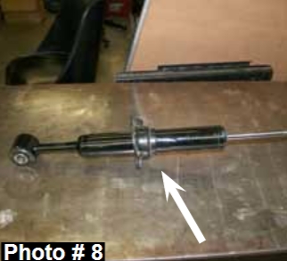
12. At the upper hex portion of the shaft, rotate the shaft of the new
Skyjacker strut assembly counter clockwise in order to unlock &
extend the shaft of the new Skyjacker strut assembly. Assemble
the new Skyjacker strut by installing the new Skyjacker coil spring
seat, new Skyjacker coil spring pad, & OEM bump stop on the
new Skyjacker strut. (See Photo # 8)
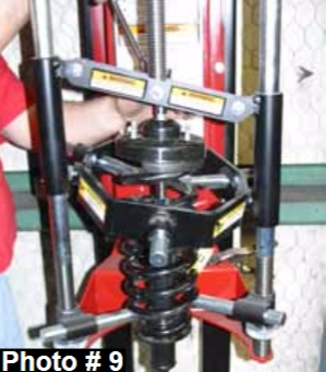
13. Slide the new Skyjacker strut assembly in from the bottom &
install the OEM rubber coil seat on top of the OEM coil. (See
Photo # 9) Important Note: Be sure that the bottom shock eye is
square with the two upper front studs on the OEM rubber mount.
14. Install the new coil / strut assembly into the vehicle. Attach to the
OEM upper mount using the OEM hardware.
15. Attach to the lower A-arm using the OEM hardware. “Ford Torque Specifications” for this bolt is 351 Ft. Lbs.
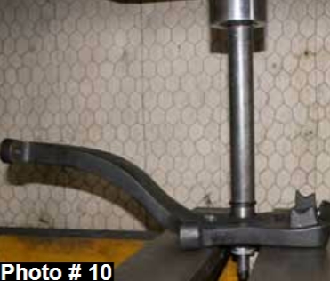
16. It will be necessary to have the OEM spindle pressed out of
the OEM steering knuckle by a qualified machine shop. Once
the spindle is pressed out, apply anti-seize compound &
press the spindle into the new Skyjacker steering knuckle.
(See Photo # 10). Note: A 10,000 lb shop press will be
needed for this step.
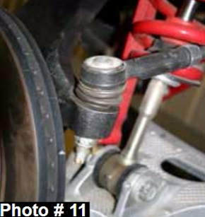
17. Attach the new Skyjacker steering knuckle to the lower A-arm
ball joint (Torque to 111 Ft. Lbs) & upper A-arm ball joint
(Torque to 85 Ft. Lbs) using the OEM hardware. (See Photo
# 11) Attach the outer tie rod using the OEM hardware.
(Torque to 111 Ft. Lbs.) Periodically re-torque upper / lower
ball joints & outer tie rod!
18. On the rearward side of the new Skyjacker steering knuckle,
there is a new mounting location for the OEM ABS line.
Using the 3/8” cable clamps & 5mm x 12mm bolts, attach
the ABS line to this new location.
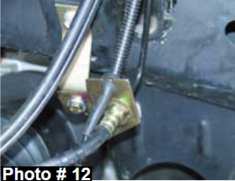
19. Locate the OEM brake line bracket on the frame rail. Remove
the OEM bracket from the frame rail & install the new
Skyjacker drop bracket at this position. Attach the new
bracket to the frame rail using the OEM hardware. Attach the
OEM brake line bracket to the new bracket using the 1/4" x 1”
fine thread bolts, washers, & nuts. (See Photo # 12)
20. Attach the brake rotor & brake caliper to the new steering
knuckle using the OEM hardware.
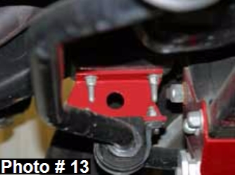
21. Install the new Skyjacker sway bar drop brackets. Attach to the
OEM mount on the frame using the OEM hardware. Attach the
sway bar to the new brackets using the 7/16" x 1 1/2” fine thread
bolts, washers, & nuts. The brackets will install with the open
portion towards the inside of the vehicle & the pointed end
towards the rear. Attach the sway bar links to the lower A-arms
using the OEM hardware. (See Photo # 13)
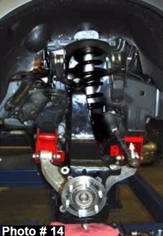
22. With the front end complete, install the front tires /wheels & lower
the vehicle to the ground. (See Photo # 14)
Rear Installation:
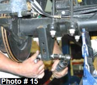
23. Raise the rear of the vehicle & support the frame rails using jack
stands. Remove the rear shocks using a 15mm & 18mm socket.
(See Photo # 15) Remove the rear u-bolts using a 21mm socket.
Disconnect the rear brake line bracket from the frame rail.
If installing rear add-a-leafs, skip to Step # 27.
Rear Spring Installation: Part # FR44S
24. To allow for the axle to lower down far enough to install the new
Skyjacker rear leaf springs, the fuel filler extension must be
disconnected from the bed. These bolts are located behind the
fuel door. The fuel extension clamp is located on the outside of
the driver side frame rail & must also be disconnected. (See
Photo # 16)
25. Lower the axle down so there is no load on the rear leaf springs.
Remove the rear leaf spring eye bolts using a 21mm socket.
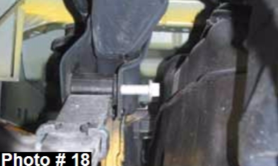
(See Photo # 17) Note: It will be necessary to loosen the gas
tank straps to allow the gas tank to slide over enough to get the
leaf spring eye bolts out. (See Photo # 18) Be sure to support the
gas tank with a transmission jack. On the passenger side, it will
be necessary to disconnect / remove the exhaust. Disconnect in
front of the muffler & remove. Remove the OEM leaf spring.
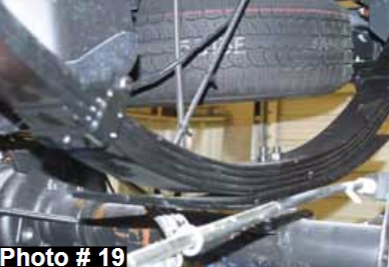
26. Install the new Skyjacker rear leaf spring on top of the OEM
block. (See Photo # 19) Note: Be sure to install the new
leaf spring with the long end of the leaf spring towards the
rear of the vehicle. There is a degree shim attached to the
bottom of the new leaf spring to correct pinion angle. Be
sure that the thick portion of the shim is towards the rear of
the vehicle. Make sure the tie bolt heads seat securely into
the OEM block. Install the new Skyjacker rear u-bolts &
torque to 130 Ft. Lbs. Skip to Step # 30. Do not tighten the
leaf spring eye bolts until the vehicle is on the ground with
the weight on the leaf springs.
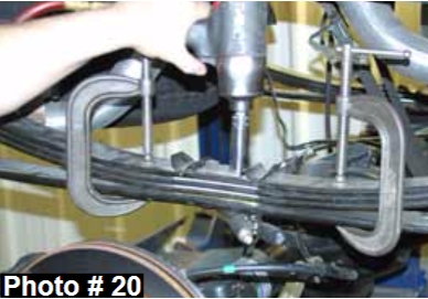
Rear Add-A-Leaf Installation: Part # R3440
27. Lower the axle to gain access to the rear leaf springs. To
perform the installation of the new Skyjacker add-a-leafs
properly you must use two large C-clamps to contain the
elastic potential energy in a leaf spring when the center tie
bolts are being removed. Attach & tighten a C-clamp on
each end of the leaf spring to hold the leaf spring assembly
securely together. Using locking pliers to hold the head of
the two center bolts, loosen & remove. With care, slowly
loosen & remove the C-clamps. (See Photo # 20)
28. Insert the new Skyjacker tie bolts through the new axle wedge shim (thick end towards the rear bumper), OEM bottom overload leaf, new add-a-leaf, & OEM leaf spring pack. Only finger tighten the nut at this time.
29. DO NOT USE THE CENTER TIE BOLTS TO DRAW THE SPRING LEAVES TOGETHER. FAILURE OF ANY COMPONENT CAN CAUSE AN EXPLOSIVE DISASSEMBLY & POSSIBLE INJURY! Place one C-clamp on each side of the new center tie bolts & tighten evenly. Once the C-clamps have drawn the leaves securely together, hold the center tie bolt heads with locking pliers & torque the nuts to 41 Ft. Lbs. Remove the C-clamps & cut off the excess length of the
tie bolts. Install the new Skyjacker u-bolts & torque to 130 Ft. Lbs.
30. Lower the vehicle to the ground & locate the new Skyjacker rear brake line extension bracket. It’s a flat bracket with a hole at each end. Attach the new bracket to the OEM mount on the frame rail using the OEM hardware. Attach the OEM bracket to the new extension bracket using the 1/4" x 1” fine thread bolt, washers, & nut. Install the new Skyjacker rear shocks.
FINAL NOTES:
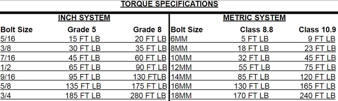
• After the installation is complete, double check that all nuts & bolts are tight. Refer to the following chart below for the proper torque specifications. (Do not retighten the nuts & bolts where thread lock compound was used.)
• With the vehicle placed on the ground, cycle the steering lock to lock & inspect the steering, suspension, brake lines, front & rear drivelines, fuel lines, & wiring harnesses for proper operation, tightness, & adequate clearance.
• Have the headlights readjusted to the proper settings.
• Have a qualified alignment center realign the front end to the factory specifications.
• Retorque all the bolts after the first 100 miles.

