FREE 1 to 3-Day Delivery on Orders $149+ Details
How to Install SkyJacker 6 in. Lift Kit on your F-150
Installation Time
1 days
Tools Required
- Metric & Standard Wrenches & Sockets
- Allen Wrenches
- Assorted Drill Bits
- Floor Jack
- Jack Stands
- Measuring Tape
- Torsion Bar Tool
- Torque Wrench
- Transmission Jack
Installation Instructions
Before beginning the installation, thoroughly & completely read these instructions & the enclosed driver’s WARNING NOTICE. Affix the WARNING decal in the passenger compartment in clear view of all occupants. Please refer to the Parts List to insure that all parts & hardware are received prior to the disassembly of the vehicle. If any parts are found to be missing, contact SKYJACKER® Customer Service at 318-388-0816 to obtain the needed items. If you have any questions or
reservations about installing this product, call SKYJACKER® Technical Assistance at 318-388-0816.
Make sure you park the vehicle on a level concrete or asphalt surface. Many times a vehicle is not level (side-to-side) from the factory & is usually not noticed until a lift kit has been installed, which makes the difference more visible. Using a measuring tape, measure the front & rear (both sides) from the ground up to the center of the fender opening above the axle. Record this information below for future reference.
Driver Side Front: ________________ Passenger Side Front:____________
Driver Side Rear: ________________ Passenger Side Rear:_____________
Important Notes:
• If larger tires (10% more than the OEM diameter) are installed, speedometer recalibration will be necessary. Contact your local Ford dealer or an authorized dealer for details.
• After installation, a qualified alignment facility is required to align the vehicle to the OEM specifications.
Front Installation:
1. With the vehicle on flat level ground, set the emergency brake & block the rear tires / wheels. Place a floor jack under the lower control arm’s front crossmember & raise the front of the vehicle. Place jack stands under the frame rails behind the front wheel wells & lower the frame onto the jack stands.
Warning: Be extremely careful when loading or unloading the torsion bars, there is a tremendous amount of stored energy (load pressure) in the torsion bars. Keep your hands & body clear of the adjuster arm assembly & puller tool in case anything slips or breaks.
Note: A special torsion bar puller tool is required for the safe removal / installation of the torsion bars. This special puller can be purchased from your local Ford dealer or most retail automotive stores.
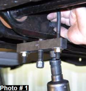
2. Measure & record the length of the OEM torsion bar adjusting bolt that is exposed below the nut. Apply a small amount of lubricating grease to the puller threads & the puller shaft-toadjuster arm contact point. Position the puller & load the adjuster arm until the torsion bar adjusting bolt & nut can be removed from the OEM rear torsion bar crossmember. With the OEM torsion bar unloaded, slide it further forward into the OEM lower control arm. If the OEM torsion bar seems lodged, use a hammer & punch through the hole in back of the OEM torsion bar crossmember. When the OEM torsion bar shifts forward, the adjuster will fall free. (See Photo # 1) Repeat this process on the opposite side.
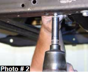
3. Remove the OEM torsion bar crossmember using a 15mm socket / wrench & 18mm socket / wrench. Remove the OEM torsion bars from the vehicle & mark them driver & passenger side for reinstallation. (See Photo # 2)
4. Remove the front tires / wheels using a 21mm socket.
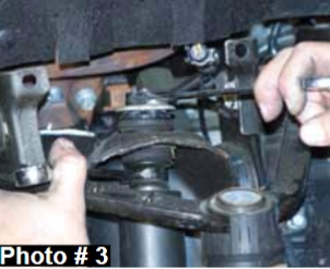
5. Remove the OEM front shocks using a 13mm socket / wrench & 18mm socket / wrench. (See Photo # 3)
6. Remove the OEM front sway bar end links using a 15mm socket / wrench & 16mm socket / wrench.
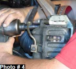
7. Remove the OEM brake calipers using a 18mm socket / wrench. (See Photo # 4) Note: It will not be necessary to disconnect the OEM brake lines from the OEM brake calipers. Simply wire them out of the way until reassembly.
8. Remove the OEM brake rotors.
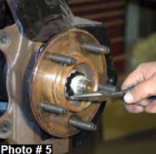
9. Remove the OEM cv-axle nuts using a 1 7/16” socket / wrench. (See Photo # 5)
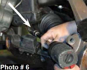
10. Remove the cv-axle flange bolts located at the front differential using a 12 point / 12mm socket / wrench & remove the OEM cv-axles from the vehicle. (See Photo # 6)
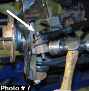
11. Remove the OEM tie rod ends from the OEM steering knuckles using a 21mm socket / wrench. Note: It may be necessary to strike the side of the steering knuckle to dislodge the tie rod end. Be careful not to damage the tie rod end. (See Photo # 7)
12. Disconnect the OEM ABS lines at the frame & remove the OEM ABS clip from the back of the OEM steering knuckles using a 8mm socket / wrench.
13. Disconnect the OEM upper & lower ball joints from the OEM steering knuckles using a 21mm socket / wrench & a 24mm socket / wrench. Remove the OEM steering knuckles from the vehicle. Note: It may be necessary to strike the side of the steering knuckle to dislodge the upper & lower ball joints. Be careful not to damage the ball joints.
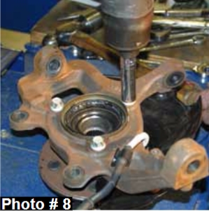
14. Remove the OEM hub bearing assemblies from the OEM steering knuckles using a 15mm socket / wrench & remove the inner seals. (See Photo # 8) Note: The OEM dust shields will not be removed or reused in the installation.
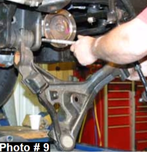
15. Remove the OEM lower a-arms. (See Photo # 9)
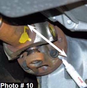
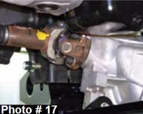
16. Mark the OEM front drive shaft at the front differential so it can be reinstalled the same as OEM during reinstallation. Disconnect the OEM front drive shaft from the front differential using a 12 point / 12mm socket / wrench. Note: It will not be necessary to remove the front drive shaft from the vehicle. Simply wire it out of the way.
(See Photo # 10)
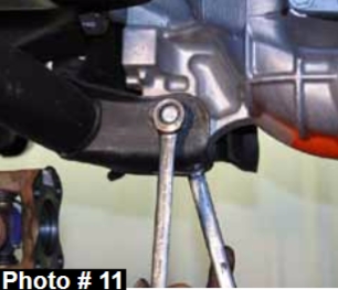
17. Remove the OEM actuator cover from the front differential using a 10mm socket / wrench. Disconnect the OEM vent hose & actuator line from the front differential. Support the front differential using a transmission jack & remove all front differential bolts using a 15mm socket / wrench & a 18mm socket / wrench. Once these bolts are removed, lower the OEM front differential out of the vehicle. (See Photo # 11)
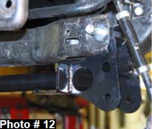
18. Install the new Skyjacker front crossmember into the OEM lower a-arm mounting holes on the frame using the supplied 5/8" x 6" fine thread bolts, washers, & nuts in the upper holes. Note: Do not tighten at this time. (See Photo # 12)
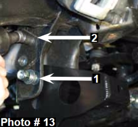
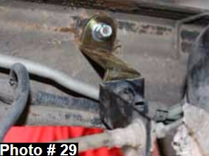
19. Install the new Skyjacker rear crossmember into the OEM lower a-arm mounting holes on the frame using the supplied 5/8" x 6" fine thread bolts, washers, & nuts in the upper holes. Note: Do not tighten at this time. (See Arrow # 1 in Photo # 13) Note: Do not remove the OEM rear crossmember until the new Skyjacker rear crossmember is installed. If the OEM crossmember is removed before the new Skyjacker crossmember is installed, the frame can possibly tweak inward making it difficult to install the new Skyjacker crossmember. Once the new Skyjacker front & rear crossmembers have been installed, tighten the new 5/8" hardware & remove the OEM rear crossmember using a 15mm socket / wrench. (See Arrow # 2 in Photo # 13)
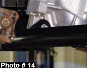
20. Install the front differential using a transmission jack & attach to the new Skyjacker front & rear crossmembers using the OEM hardware. (See Photo # 14)
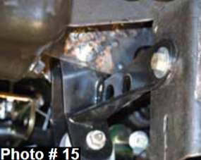
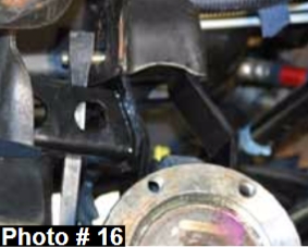
21. Install the new Skyjacker passenger side differential bracket. (See Photo # 15 & Photo # 16) Install the OEM bolt at the bottom hole & install the supplied 7/16" x 4" fine thread bolt, washers, & nut in the upper hole. Attach the new passenger side differential bracket to the OEM lower control arm mount on the frame using the supplied 1/2" x 1 1/2" fine thread bolt, washers, & nut.
22. Install the OEM front drive shaft to the front differential using the OEM hardware.
23. Install the OEM lower a-arms to the new Skyjacker crossmembers using the supplied 5/8" x 6" fine thread bolts, washers, & nuts.
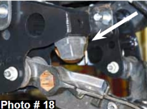
24. Remove the OEM bump stops from the OEM lower a-arms using a 15mm socket / wrench & attach to the new Skyjacker rear crossmember using the OEM hardware. (See Photo # 18)
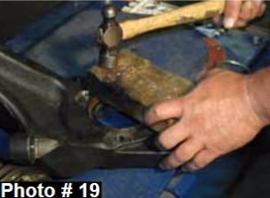
25. Install the inner seals into the new Skyjacker steering knuckles. Note: It may be necessary to use a wooden block to allow full contact while installing the inner seals. (See Photo # 19)
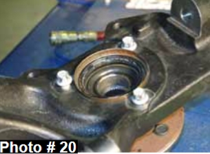
26. Install the OEM hub assemblies to the new Skyjacker steering knuckles using the OEM hardware. Note: Do not use the OEM dust shields. (See Photo # 20)
27. Install the new Skyjacker steering knuckles to the OEM upper & lower a-arm ball joints using the OEM hardware.
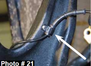
28. Move the ABS clip up on the OEM ABS lines so they align with the 5mm hole on the rear of the new Skyjacker steering knuckles & attach the OEM ABS lines to the new steering knuckles using the supplied 5mm x 12mm bolts. (See Photo # 21) Note: It may be necessary to use a spray lubricant to allow the OEM ABS clips to slide up the OEM ABS lines.
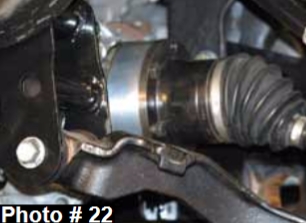
29. Install the OEM passenger side cv-axle using the OEM hardware. Install the OEM driver side cv-axle using the supplied cv-axle spacer, 12mm x 65mm bolts, & thread locking compound. (See Photo # 22) Note: Install the new cv-axle spacer with the male end against the front differential flange.
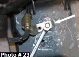
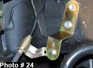
30. Disconnect the OEM front brake line brackets from the frame using a 10mm socket / wrench. (See Photo # 23) Install the new Skyjacker brake line brackets to the frame using the OEM hardware for the upper hole & align the middle hole of the new brake line brackets with the hole already in the frame. Drill these holes using a 9/32" drill bit & install the supplied 3/8" x 1" thread cutter bolts. Attach the OEM brake lines to the new brake line brackets using the supplied 5/16" x 1" coarse thread bolts, washers, & nuts. (See Photo # 24)
31. Install the OEM brake calipers using the OEM hardware & a 18mm socket / wrench.
32. Install the OEM outer tie rod ends to to the new Skyjacker steering knuckles using the OEM hardware & a 21mm socket / wrench.
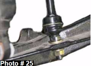
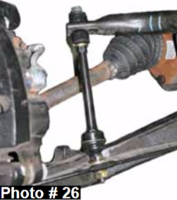
33. Install the new Skyjacker sway bar end link bushings on the stud of the pivoting end of each new Skyjacker sway bar end link with the larger diameter end facing the boot of the new sway bar end link. Align the new sway bar end link bushings with the OEM mounting location of the OEM a-arm & install the new Skyjacker sway bar end links. Note: Be sure to install the new sway bar end links with the pivoting end at the a-arm. (See Photo # 25 & Photo # 26)
34. Install the new Skyjacker shocks using the supplied hardware, OEM hardware, a 13mm socket / wrench, & a 18mm socket / wrench.
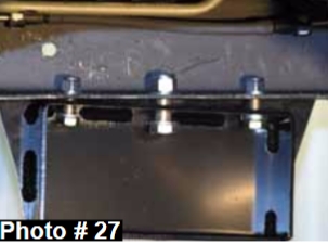
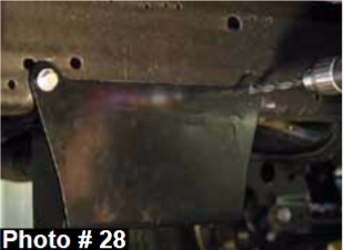
35. Install the new Skyjacker torsion bar brackets to the OEM holes in the bottom of the frame rail using the supplied 5/8" x 1 1/2" fine thread bolts in the middle mounting holes & the supplied 1/2" x 1 1/2" fine thread bolts in the outer bottom holes. (See Photo # 27) Mark, center punch, & drill the outside frame holes using a 15/32” drill bit & install the supplied 7/16" x 1 1/2" fine thread bolts, washers, & nuts. (See
Photo # 28). Note: Before completely installing the new torsion bar brackets, attach the OEM torsion bar crossmember to the new torsion bar brackets.
36. Install the OEM torsion bars using the OEM hardware.
37. Install the front tires / wheels using a 21mm socket & lower the front of the vehicle to the ground.
Rear Installation:
1. With the vehicle on flat level ground, block the front tires / wheels.
2. Place a floor jack under the vehicle & raise the rear of the vehicle. Place the jack stands under the frame rails & lower the frame of the vehicle onto the jack stands.
3. Remove the rear tires / wheels using a 21mm socket.
4. Disconnect the OEM rear brake line bracket from the frame & install the new Skyjacker brake line bracket to the frame using the supplied 5/16" x 3/4" coarse thread bolt, washer, & nut. Attach the OEM brake line to the new brake line bracket using the OEM hardware. (See Photo # 29)
5. Remove the OEM rear shocks using a 18mm socket / wrench.
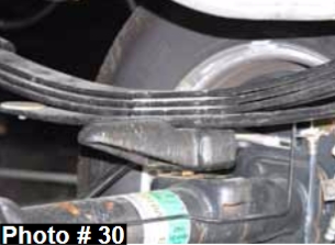
6. Support the rear axle & remove the OEM rear u-bolts using a 21mm socket / wrench. (See Photo # 30)
7. While checking for appropriate slack in ABS lines, brake lines, differential breather hose, & etc., lower the rear axle.
If installing rear lift blocks, proceed to Step # 9
Rear Spring Installation:
8. Remove the OEM rear leaf springs using a 21mm socket / wrench. Install the new Skyjacker rear leaf springs on top of the OEM blocks with the thickest part of the degree shim towards the rear of the vehicle using the OEM hardware. Note: Do not fully tighten the OEM leaf spring eye bolts until the rear of the vehicle has been lowered to the ground in Step # 12. Proceed to Step # 10.
Rear Lift Block Installation:
9. Install the new Skyjacker rear lift blocks under the OEM rear blocks with the tallest end of the new rear lift blocks toward the rear of the vehicle.
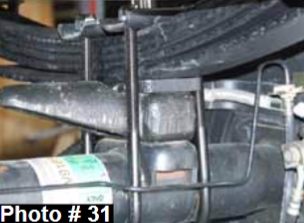
10. Raise the rear axle & install the new Skyjacker rear u-bolts using the supplied 9/16" nuts & a 7/8" socket / wrench. (See Photo # 31)
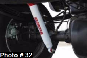
11. Install the new Skyjacker rear shocks using the supplied hardware, OEM hardware, & a 18mm socket / wrench. (See Photo # 32)
12. Install the rear tires / wheels using a 21mm socket & lower the rear of the vehicle to the ground.
Final Notes:
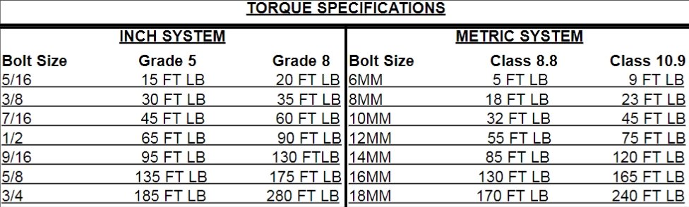
• After the installation is complete, double check that all nuts & bolts are tight. Refer to the following chart for the proper torque specifications. (Do not retighten the nuts & bolts where thread lock compound was used.)
• With the vehicle placed on the ground, cycle the steering lock to lock & inspect the steering, suspension, brake lines, front & rear drivelines, fuel lines, & wiring harnesses for proper operation, tightness, & adequate clearance.
• Have the headlights readjusted to the proper settings.
• Have a qualified alignment center align the vehicle to the OEM specifications.
• After the first 100 miles, check all hardware for the proper torque & periodically thereafter.
Important Note:
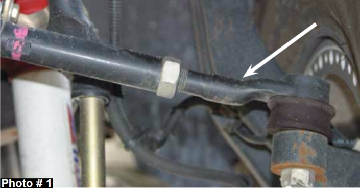
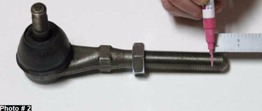
The front end alignment should be set to the OEM specifications. Some models will require cutting of the OEM outer tie rod end adjustment threads to obtain the proper toe in. Remove the OEM outer tie rod ends from the new Skyjacker steering knuckles & OEM adjusting sleeves. (See Photo # 1) Thread the OEM jam nut all the way down until it bottoms out on the OEM tie rod ends. Measure 3/8” from the end of the threads & mark. Cut along the previously made mark with a die
grinder, hack saw, or similar tool. (See Photo # 2) Unscrew the OEM jam nut to chase the threads of the OEM tie rod ends & reinstall the OEM tie rod ends onto the OEM adjusting sleeves & new Skyjacker steering knuckles. The driver & passenger side tie rod end threads must be cut equally & adjusted equally to allow for proper toe in adjustment.
Arrow below shows the OEM outer tie rod end.