 FREE 1 to 3-Day Delivery on Orders $149+ Details
How to Install SkyJacker 4.5 in. Suspension Lift Kit on your F-150
Installation Time
1 days
Tools Required
- Safety Glasses
- Metric / Standard Wrenches & Sockets
- Hex Key Wrenches
- Floor Jack / Jack Stands
- Drill / Assorted Drill Bits
- Measuring Tape
- Torque Wrench
- Reciprocating Saw / Grinder

Shop Parts in this Guide
Before beginning the installation, thoroughly & completely read these instructions & the enclosed driver’s WARNING NOTICE. Affix the WARNING decal in the passenger compartment in clear view of all occupants. Please refer to the Parts List to insure that all parts & hardware are received prior to the disassembly of the vehicle. If any parts are found to be missing, contact SKYJACKER® Customer Service at 318-388-0816 to obtain the needed items. If you have any questions or reservations about installing this product, contact SKYJACKER® Technical Assistance at 318-388- 0816.
Make sure you park the vehicle on a level concrete or asphalt surface. Many times a vehicle is not level (side-to-side) from the factory & is usually not noticed until a lift kit has been installed, which makes the difference more visible. Using a measuring tape, measure the front & rear (both sides) from the ground up to the center of the fender opening above the axle. Record this information below for future reference.
Driver Side Front: ______________ Passenger Side Front___________________:
Driver Side Rear: ______________ Passenger Side Rear:___________________
IMPORTANT NOTES:
• 20" diameter or larger wheels must be used to install this suspension lift.
• If larger tires (10% more than the OEM diameter) are installed, speedometer recalibration will be necessary. Contact your local Ford dealer or an authorized dealer for details.
• After installation, a qualified alignment facility is required to align the vehicle to the OEM specifications.
Front Installation:
1. With the vehicle on flat level ground, set the emergency brake &
block the rear tires / wheels.
2. Place a floor jack under the lower control arm front cross member & raise the vehicle. Place jack stands under the frame rails, behind the front wheel wells & lower the frame of the vehicle onto the jack stands.
3. Remove the front tires / wheels using a 13/16" socket.
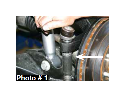
4. Disconnect the OEM outer tie rod ends from the OEM steering knuckles using a 21mm socket / wrench & tie rod remover or other suitable tool. (See Photo # 1)
5. Remove the OEM brake line brackets & OEM brake caliper mounting bolts from the OEM steering knuckles using a 10mm socket / wrench & a 21mm socket / wrench. Remove the OEM brake caliper assemblies & simply wire the OEM brake caliper assemblies out of the way. It will not be necessary to disconnect the OEM brake lines from the OEM brake caliper assemblies.
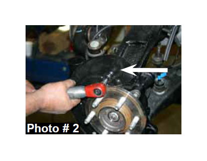
6. Remove the OEM brake rotors & remove the OEM disc brake shields using a 8mm socket / wrench. (See Photo # 2)
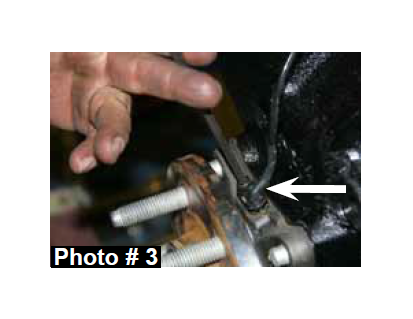
7. Remove the OEM ABS sensors & OEM ABS sensor brackets from the OEM steering knuckles using a 5mm hex key & 8mm socket / wrench. (See Photo # 3)
8. Disconnect the OEM intergrated vaccum lines from the OEM 4WD actuator & the upper frame connection.
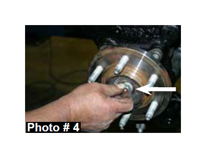
9. Remove the OEM cv-shaft nuts from the center of the OEM hub assemblies using a 15mm socket. (See Photo # 4)
10. Disconnect the OEM upper sway bar end links using a 18mm socket / wrench. Remove the OEM sway bar & OEM sway bar mounting brackets from the frame using a 15mm socket / wrench.
11. Remove the OEM upper & lower ball joints from the OEM steering knuckles using a 18mm socket / wrench, a 21mm socket / wrench, & a ball joint remover or other suitable tool.
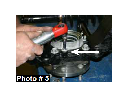
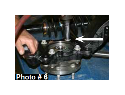
12. Remove the OEM steering knuckles. Once removed, remove the three OEM 4WD actuator bolts & the four OEM hub bearing assembly bolts from the OEM steering knuckles using a 8mm socket / wrench & a 18mm socket / wrench. (See Photos # 5 & # 6)
13. Remove the OEM lower strut mount bolts from the OEM lower control arms using a 18mm socket / wrench.
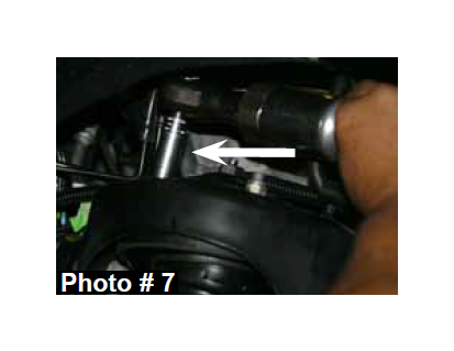
14. Remove the three OEM upper strut retaining nuts from each OEM strut assembly using a 15mm socket / wrench. (See Photo # 7) Once removed, remove the OEM strut assemblies.
15. Remove the OEM front & rear lower control arm bolts using a 21mm socket / wrench & a 27mm socket / wrench. Once removed, remove the OEM lower control arms.
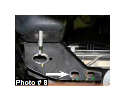
16. Remove the four OEM rear cross member frame connecting bolts using a 15mm socket / wrench & remove the OEM rear cross member. (See Photo # 8)
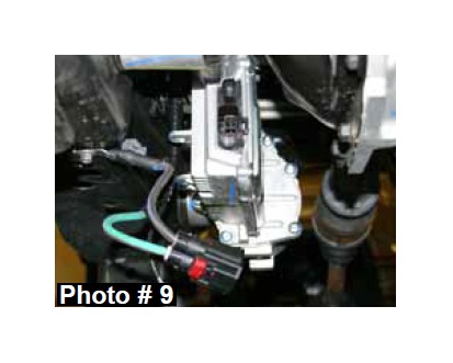
17. Disconnect all electrical connections & the OEM steering shaft from the OEM rack & pinion. Remove the OEM rack & pinion. (See Photo # 9)
18. Mark the position of the OEM front differential flange & OEM drive shaft flange. Note: These marks will be realigned during reassembly. Remove the six OEM front drive shaft mounting bolts from the OEM front differential using a 10mm socket / wrench. It will not be necessary to remove the OEM drive shaft from the OEM transfer case. Simply wire the OEM drive shaft out of the way.
19. Support the OEM front differential with a transmission jack & remove the OEM differential mounting bolts using a 18mm socket / wrench & a 21mm socket / wrench. There are two on the driver side (Front & Rear) & one on the passenger side. Once these bolts are removed, lower the OEM front differential out of the vehicle.
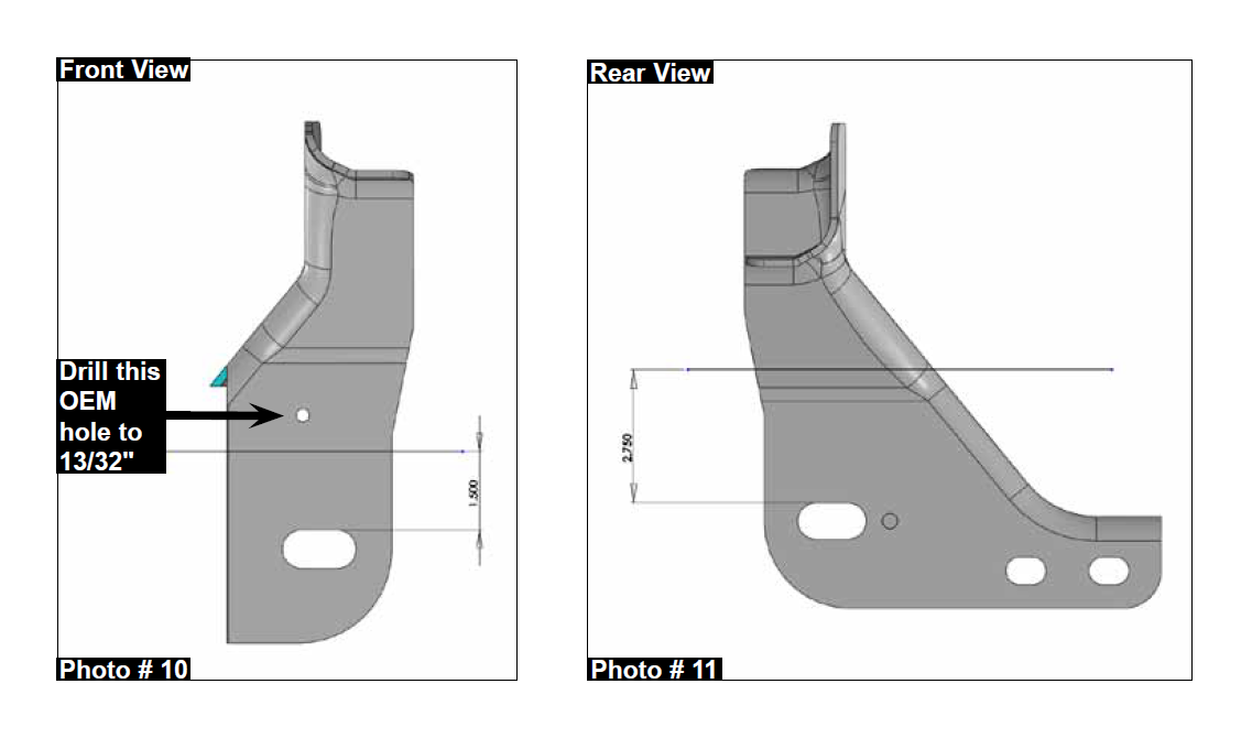
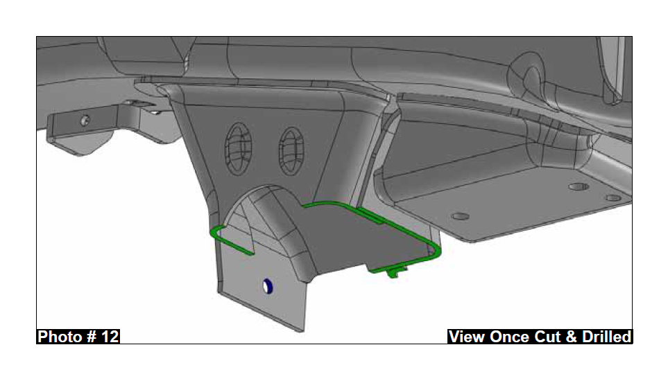
20. It will now be necessary to cut the OEM rear cross member for differential clearance when the lift is installed. Locate the OEM driver side rear cross member bracket, measure from the top of the slotted hole of the OEM bracket up 1.5" & draw a straight line along the front outer edge of the OEM bracket. (See Photo # 10) Measure from the top of the slotted hole of the OEM bracket up 2.75" & draw a straight line along the rear outer edge of the OEM bracket. (See Photo # 11) Cut along the drawn lines using a grinder or reciprocating saw. Drill the OEM hole located on the front outer edge of the OEM bracket using a drill & 13/32" drill bit. (See Photo # 10) Refer to the picture provided for an example of what the OEM brackets will look like once cut & drilled. (See Photo # 12)
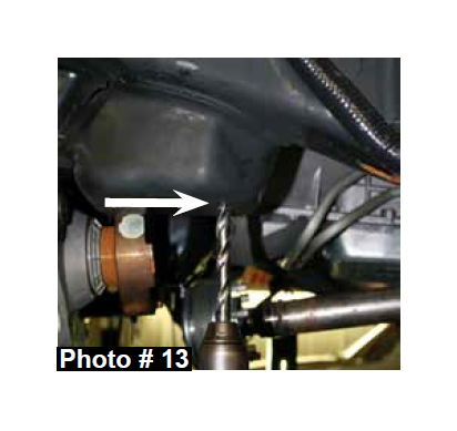
21. Drill the two OEM sway bar mounting bracket holes located on
the driver side frame using a drill & 1/2" drill bit. (See Photo # 13)
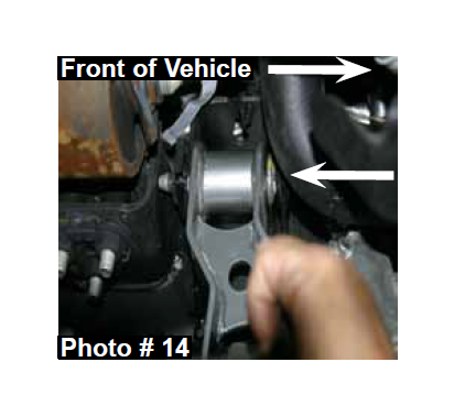
22. Install the new Skyjacker driver side (Part # F960DDB-B) & passenger side (Part # F960PDB-B) front differential brackets in the OEM location with the offset of the new brackets facing toward the front of the vehicle, using the OEM hardware, a 18mm socket / wrench, & a 21mm socket / wrench. Do not tighten at this time. (See Photo # 14)
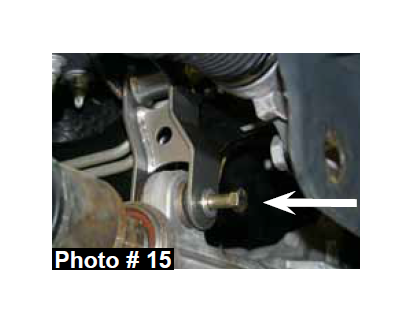
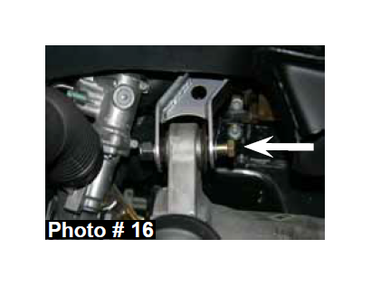
23. Support the OEM front differential with a transmission jack & install the OEM front differential. Install the supplied 14mm x 90mm bolts, 9/16" washers, & 14mm nuts in the lower mounting location of the new Skyjacker driver & passenger side front differential brackets using a 21mm socket / wrench & a 22mm socket / wrench. Note: The supplied 9/16" washers are to be installed on the hex head side of the supplied 14mm x 90mm bolts. Do not tighten at this time. (See Photos # 15 & # 16)
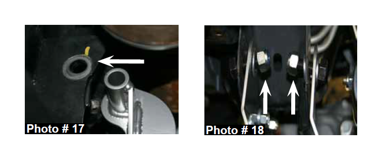
24. Install the new Skyjacker driver side rear differential bracket in the OEM location with the flat side of the new bracket facing toward the front of the vehicle, using the OEM hardware & a 21mm socket / wrench. Do not tighten at this time. (See Photo # 17)
25. Install the OEM rack & pinion. Reconnect the OEM steering shaft & all electrical connections to the OEM rack & pinion. (See Photo # 9)
26. Install the new Skyjacker rear cross member, with the driver side intergrated sway bar lowering bracket facing toward the rear of the vehicle. Install the supplied 18 x 50mm bolts, 3/4" washers, & 18mm nuts in the passenger side upper two holes of the new rear cross member using a 27mm socket / wrench. Do not tighten at this time. (See Photo # 18)
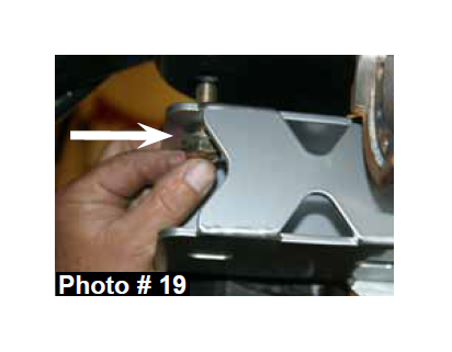
27. Install the supplied 1/2" x 1 1/2" bolts, 1/2" washers, & 1/2" nuts in the two holes of the new Skyjacker intergrated sway bar lowering bracket using a 3/4" socket / wrench. Do not tighten at this time. (See Photo # 19)
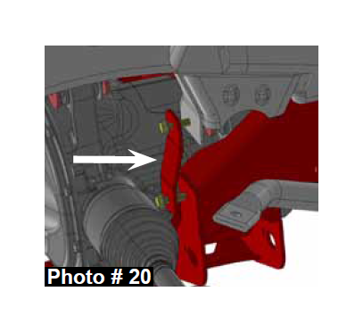
28. Install the new Skyjacker rear cross member brace using the supplied 3/8" x 1 1/4" bolts, 3/8" washers, & 3/8" nuts in the front holes of the OEM rear cross member bracket & new Skyjacker rear cross member using a 9/16" socket / wrench. (See Photo # 20)
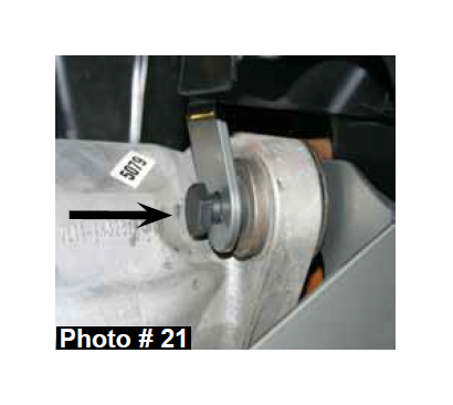
29. Install the supplied 14mm x 90mm bolt & 14mm nut in the lower mounting hole of the new Skyjacker driver side rear differential bracket & rear cross member using a 21mm socket / wrench & a 22mm socket / wrench. Do not tighten at this time. (See Photo # 21)
30. Install the supplied 1/2" x 1 1/2" bolts, 1/2" washers, & 1/2" nuts in
the two rear holes of the passenger side OEM cross member
bracket & new Skyjacker cross member using a 3/4" socket /
wrench. Do not tighten at this time.
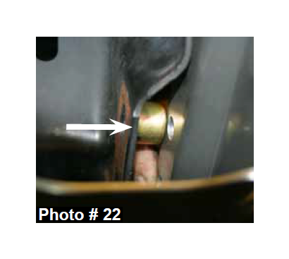
31. Install the supplied 13/16" long crush sleeves, 1/2" x 2" bolts, 1/2" washers, & 1/2" nuts in the two front holes of the passenger side OEM cross member bracket & new Skyjacker cross member using a 3/4" socket / wrench. Do not tighten at this time. (See Photo # 22)
32. Tighten the 1/2" x 1 1/2" bolts & 1/2" nuts located on the new Skyjacker intergrated sway bar lowering bracket using a 3/4" socket / wrench.
33. Tighten the 18mm x 50mm bolts & 18mm nuts in the passenger side upper rear cross member using a 27mm socket / wrench.
34. Tighten the 1/2" x 1 1/2" bolts, 1/2" x 2" bolts & 1/2" nuts of the front & rear passenger side OEM cross member bracket & new Skyjacker cross member using a 3/4" socket / wrench.
35. Tighten the 14mm x 90mm bolt, 14mm nut, & OEM bolt on the upper & lower mounting locations of the new Skyjacker driver side rear differential bracket & rear cross member using a 21mm socket / wrench & a 22mm socket / wrench.
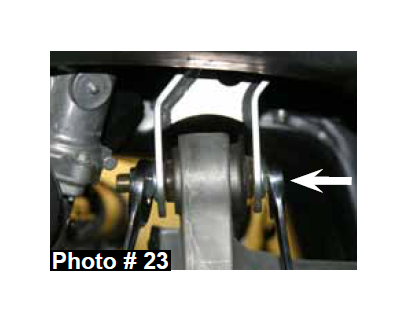
36. Tighten the 14mm x 90mm bolts, 14mm nuts, & OEM hardware on the upper & lower mounting locations of the new Skyjacker driver & passenger side front differential brackets using a 18mm socket / wrench, a 21mm socket / wrench, & a 22mm socket / wrench. (See Photo # 23)
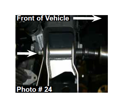
37. Install the new Skyjacker front cross member with the offset facing toward the front of the vehicle. Install the supplied 18mm x 150mm bolts, 3/4" washers, & 18mm nuts in the upper two holes of the new Skyjacker cross member using a 21mm socket / wrench & a 27mm socket / wrench. (See Photo # 24)
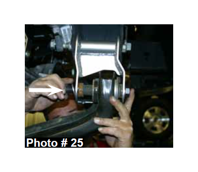
38. Install the OEM hardware in the the lower front & rear cross member mounts & lower control arms using a 21mm socket / wrench & a 27mm socket / wrench. (See Photo # 25)
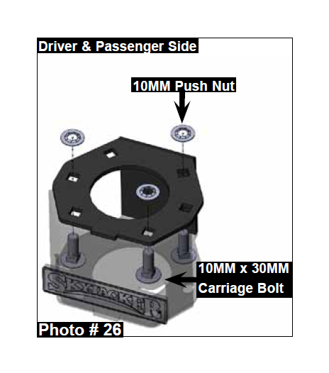
39. Assemble the new Skyjacker strut spacers using the supplied 10mm x 30mm carriage bolts, & 10mm push nuts. (See Photos # 26)
40. Install the new Skyjacker strut spacers on the top of each OEM strut assembly using the OEM hardware & a 15mm socket / wrench. Do not tighten at this time.
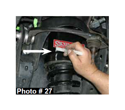
41. Install the strut / spacer assemblies & align the three studs of each new strut spacer with the OEM mounting locations. For alignment purposes, mark the location of the upper strut mount & new strut spacer. (See Photo # 27)
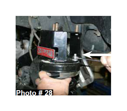
42. Remove the strut / spacer assemblies. Align the previously made marks & tighten the new strut spacers to the OEM strut assemblies using a 15mm socket / wrench. (See Photo # 28)
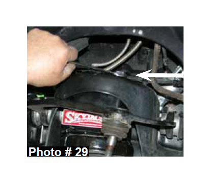
43. Install the strut / spacer assemblies by aligning the three upper strut mount studs with the OEM mounting locations using the supplied 10mm nuts & a 15mm socket / wrench. (See Photo # 29)
44. Install the OEM hub bearing assemblies to the new Skyjacker
steering knuckles using the OEM hardware. Apply thread lock to
the threads of each bolt & tighten using a 18mm socket / wrench.
Note: Make sure that the OEM ABS sensor connection is pointing
upward. (See Photo # 7)
45. Install the OEM 4WD actuators using the OEM hardware & a 8mm socket / wrench. Note: Make sure that the OEM hose connections are pointing upward. (See Photo # 6)
46. Install the new Skyjacker steering knuckles to the OEM lower control arm ball joints using the OEM hardware & a 21mm socket / wrench.
47. Install the OEM lower strut mount using the OEM hardware & a 18mm socket / wrench.
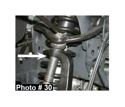
48. Install the OEM cv-shafts using the OEM hardware & a 15mm socket / wrench. Install the OEM upper ball joints to the new Skyjacker steering knuckles using the OEM hardware & a 18mm socket / wrench. Note: It may be necessary to use a jack to raise the OEM lower control arms in order to install the OEM upper ball joints. (See Photo # 30)
49. Install the OEM ABS sensors & ABS sensor brackets to the new Skyjacker steering knuckles using the OEM hardware, a 5mm hex key, a 8mm socket / wrench, & the supplied plastic ties. (See Photo # 3)
50. Install the new Skyjacker 7/64" & 5/32" vaccum lines for the OEM 4WD actuator & upper frame connection using the supplied plastic ties.
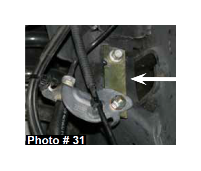
51. Disconnect the OEM front brake line brackets from the frame using a 10mm socket / wrench. Install the new Skyjacker front brake line extension brackets using the OEM hardware, the supplied 1/4" x 1" bolts, nuts, & washers, a 10mm socket / wrench, & a 7/16" socket / wrench. (See Photo # 31)
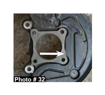
52. Install the OEM disc brake shields using the OEM hardware & a 8mm socket / wrench. Note: Some models may require the inside edge of the OEM disc brake shields to be ground in order for the OEM disc brake shields to fit flush to the new Skyjacker steering knuckles. (See Photo # 32)
53. Install the OEM brake rotors, brake line brackets, & brake caliper assemblies using the OEM hardware, a 10mm socket / wrench, & a 21mm socket / wrench.
54. Install the OEM outer tie rod ends to the new Skyjacker steering knuckles using the OEM hardware & a 21mm socket / wrench.
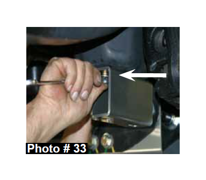
55. Install the new Skyjacker sway bar drop bracket on the passenger side frame using the supplied 7/16" x 1 1/2" bolts, 7/16" washers, 7/16" nuts, a 5/8" socket / wrench. (See Photo # 33)
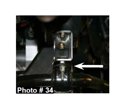
56. Install the OEM sway bar to the new Skyjacker sway bar lowering brackets using the OEM hardware & a 15mm socket / wrench. (See Photo # 34)
57. Connect the OEM sway bar end links to the OEM sway bar using
the OEM hardware & a 18mm socket / wrench.
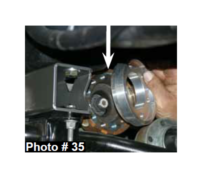
58. Install the new Skyjacker front drive shaft spacer with the male side facing the differential using the supplied 10mm x 80mm socket head bolts, OEM retaining rings, & a 8mm hex key. Note: Apply thread lock to the threads of these bolts & be sure to align the previously made marks on the OEM front differential flange & OEM drive shaft flange. (See Photo # 35)
59. Install the new Skyjacker front differential skid plate to the new Skyjacker front & rear cross members using the supplied 5/16" x 1" carriage bolts, 5/16" SAE washers, 5/16" nuts, & a 1/2" socket / wrench.
60. Install the front tires / wheels using a 13/16" socket & lower the front of the vehicle to the ground.
Rear Installation:
1. With the vehicle on flat level ground, block the front tires / wheels.
2. Place a floor jack under the vehicle & raise the rear of the vehicle. Place the jack stands under the frame rails & lower the frame of the vehicle onto the jack stands.
3. Remove the rear tires / wheels using a 13/16" socket.
4. Remove the OEM rear shocks & disconnect the OEM rear brake line bracket from the frame rail using a 13mm socket / wrench, a 15mm socket / wrench, & a 18mm socket / wrench.
5. Support the rear axle & remove the rear OEM u-bolts using a 21mm socket / wrench.
6. 4.5" Lift: While checking for appropriate slack in ABS lines, brake lines, differential breather hose, & etc. Lower the rear axle & remove the OEM rear blocks. Install the new Skyjacker 4.5" rear lift blocks with the taller end of the new rear lift blocks toward the rear of the vehicle.
7. 6" Lift: While checking for appropriate slack in ABS lines, brake lines, differential breather hose, & etc. Lower the rear axle & install the new Skyjacker 4.5" rear lift blocks on top of the OEM rear blocks with the taller end of the new rear lift blocks toward the rear of the vehicle.
8. Raise the rear axle & install the new Skyjacker rear u-bolts using the supplied 9/16" nuts & a 7/8" socket / wrench.
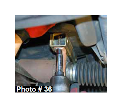
9. On models equipped with a carrier bearing on the rear driveshaft, it will be necessary to install the supplied carrier bearing lowering bracket to help eliminate any driveline vibration. Install using the supplied 10mm x 90mm bolts, washers, & a 17mm socket / wrench. The bracket will mount between the OEM carrier bearing & the OEM mount on the frame. (See Photo # 36)
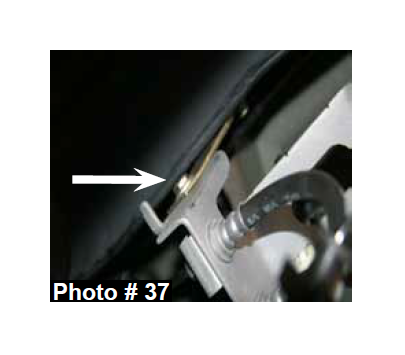
10. Install the new Skyjacker rear brake line bracket to the OEM mount on the frame rail using the OEM hardware & a 13mm socket / wrench. Connect the OEM brake line bracket to the new brake line bracket using the supplied 1/4" x 1" bolt, 1/4" washers, 1/4" nut, & a 7/16" socket / wrench. (See Photo # 37)
11. Install the new Skyjacker rear shocks using the supplied hardware, OEM hardware, a 15mm socket / wrench, & a 18mm socket / wrench.
12. Install the rear tires / wheels using a 13/16" socket & lower the rear of the vehicle to the ground.
Final Notes:
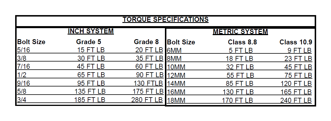
• After the installation is complete, double check that all nuts & bolts are tight. Refer to the following chart for the proper torque specifications. (Do not retighten the nuts & bolts where thread lock compound was used.)
• With the vehicle placed on the ground, cycle the steering lock to lock & inspect the steering, suspension, brake lines, front & rear drivelines, fuel lines, & wiring harnesses for proper operation, tightness, & adequate clearance.
• Have the headlights readjusted to the proper settings.
• Have a qualified alignment center align the vehicle to the OEM specifications.
• The above specifications are not to be used when the bolt is being installed with a bushing.
• After the first 100 miles, check all hardware for the proper torque & periodically thereafter.
